Chapter 22 Materials Selection and Design Considerations
Chapter 22 Materials Selection and Design Considerations
Chapter 22 Materials Selection and Design Considerations

Create successful ePaper yourself
Turn your PDF publications into a flip-book with our unique Google optimized e-Paper software.
Tensile Tests<br />
<strong>22</strong>.8 Testing Procedure <strong>and</strong> Results • W107<br />
(a) (b)<br />
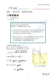
Figure <strong>22</strong>.<strong>22</strong> (a) Scanning electron micrograph of the fracture surface for the impact<br />
specimen prepared from the center-core region of the failed axle. 120�. (b) Scanning<br />
electron micrograph of the fracture surface for the impact specimen prepared from the<br />
center-core region of the failed axle taken at a higher magnification than (a); interspersed<br />
cleavage <strong>and</strong> dimpled features may be noted. 3000�. [Reproduced with permission from<br />
H<strong>and</strong>book of Case Studies in Failure Analysis, Vol. 1 (1992), ASM International, <strong>Materials</strong><br />
Park, OH, 44073-0002.]<br />
A tensile specimen taken from the center-core region was pulled in tension to failure.<br />
The fractured specimen displayed the cup-<strong>and</strong>-cone configuration, which indicated<br />
at least a moderate level of ductility. A fracture surface was examined using<br />
the SEM, <strong>and</strong> its morphology is presented in the micrograph of Figure <strong>22</strong>.23. The<br />
Figure <strong>22</strong>.23 Scanning electron micrograph<br />
of the fracture surface for the inner-core<br />
specimen that was tensile tested; a<br />
completely dimpled structure may be noted.<br />
Approximately 3500�.<br />
[Reproduced with<br />
permission from H<strong>and</strong>book of Case Studies<br />
in Failure Analysis, Vol. 1 (1992), ASM<br />
International, <strong>Materials</strong> Park, OH,<br />
44073-0002.]