Chapter 22 Materials Selection and Design Considerations
Chapter 22 Materials Selection and Design Considerations
Chapter 22 Materials Selection and Design Considerations

Create successful ePaper yourself
Turn your PDF publications into a flip-book with our unique Google optimized e-Paper software.
W98 • <strong>Chapter</strong> <strong>22</strong> / <strong>Materials</strong> <strong>Selection</strong> <strong>and</strong> <strong>Design</strong> <strong>Considerations</strong><br />
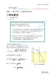
Goodman’s law—<br />
computation of the<br />
nonzero-mean-stress<br />
fatigue limit for a<br />
material using<br />
tensile strength <strong>and</strong><br />
zero-mean-stress<br />
fatigue limit values<br />
150,000 min. At 3000 rpm, the total number of revolutions is (3000 rev/min)(150,000<br />
min) rev, <strong>and</strong> since there are 2 rev/cycle, the total number of cycles is<br />
This result means that we may use the fatigue limit as the design stress<br />
inasmuch as the limit cycle threshold has been exceeded for the 100,000-mile<br />
distance of travel (i.e., since cycles 7 10 cycles).<br />
Furthermore, this problem is complicated by the fact that the stress cycle is<br />
not completely reversed (i.e., tm � 0)<br />
inasmuch as between minimum <strong>and</strong> maximum<br />
deflections the spring remains in compression; thus, the 45,000 psi (310 MPa)<br />
fatigue limit is not valid. What we would now like to do is first to make an appropriate<br />
extrapolation of the fatigue limit for this tm � 0 case <strong>and</strong> then compute<br />
<strong>and</strong> compare with this limit the actual stress amplitude for the spring; if the stress<br />
amplitude is significantly below the extrapolated limit, then the spring design is<br />
satisfactory.<br />
A reasonable extrapolation of the fatigue limit for this tm � 0 situation may be<br />
made using the following expression (termed Goodman’s law):<br />
6<br />
2.25 � 108 2.25 � 108 � 4.5 � 10<br />
.<br />
8<br />
t al � t e a1 � t m<br />
0.67TS b<br />
(<strong>22</strong>.19)<br />
where tal is the fatigue limit for the mean stress tm; te is the fatigue limit for<br />
tm � 0 [i.e., 45,000 psi (310 MPa)]; <strong>and</strong>, again, TS is the tensile strength of the<br />
alloy. To determine the new fatigue limit tal from the above expression necessitates<br />
the computation of both the tensile strength of the alloy <strong>and</strong> the mean stress<br />
for the spring.<br />
<strong>22</strong>.6 ONE COMMONLY EMPLOYED STEEL ALLOY<br />
One common spring alloy is an ASTM 232 chrome–vanadium steel, having a composition<br />
of 0.48–0.53 wt% C, 0.80–1.10 wt% Cr, a minimum of 0.15 wt% V, <strong>and</strong> the<br />
balance being Fe. Spring wire is normally cold drawn (Section 11.4) to the desired<br />
diameter; consequently, tensile strength will increase with the amount of drawing<br />
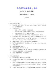
For an ASTM 232<br />
steel wire,<br />
dependence of<br />
tensile strength on<br />
drawn wire diameter<br />
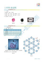
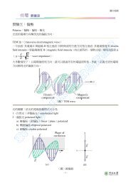
45,000 psi<br />
Stress amplitude, S<br />
10 3<br />
0.67TS<br />
10 5<br />
Cycles to failure, N<br />
(logarithmic scale)<br />
10 7<br />
(i.e., with decreasing diameter). For this alloy it has been experimentally verified<br />
that, for the diameter d in inches, the tensile strength is<br />
TS 1psi2 � 169,0001d2 �0.167<br />
10 9<br />
Figure <strong>22</strong>.9 Shear<br />
stress amplitude versus<br />
logarithm of the number<br />
of cycles to fatigue failure<br />
for typical ferrous alloys.<br />
(<strong>22</strong>.20)