Chapter 22 Materials Selection and Design Considerations
Chapter 22 Materials Selection and Design Considerations
Chapter 22 Materials Selection and Design Considerations

Create successful ePaper yourself
Turn your PDF publications into a flip-book with our unique Google optimized e-Paper software.
<strong>22</strong>.5 Valve Spring <strong>Design</strong> <strong>and</strong> Material Requirements • W97<br />
which, from Equation <strong>22</strong>.15, gives an installed deflection per coil of<br />
d ic �<br />
� 0.060 in./coil (1.5 mm/coil)<br />
The cam lift is 0.30 in. (7.6 mm), which means that when the cam completely opens a<br />
valve, the spring experiences a maximum total deflection equal to the sum of the valve<br />
lift <strong>and</strong> the compressed deflection, namely, 0.30 in. � 0.24 in. � 0.54 in. (13.7 mm).<br />
Hence, the maximum deflection per coil, is<br />
d mc �<br />
0.24 in.<br />
4 coils<br />
0.54 in.<br />
4 coils<br />
d mc,<br />
� 0.135 in./coil (3.4 mm/coil)<br />
Thus, we have available all of the parameters in Equation <strong>22</strong>.18 (taking ),<br />
except for the required shear yield strength of the spring material.<br />
However, the material parameter of interest is really not inasmuch as the<br />
spring is continually stress cycled as the valve opens <strong>and</strong> closes during engine<br />
operation; this necessitates designing against the possibility of failure by fatigue<br />
rather than against the possibility of yielding. This fatigue complication is h<strong>and</strong>led<br />
by choosing a metal alloy that has a fatigue limit (Figure 8.19a) that is greater<br />
than the cyclic stress amplitude to which the spring will be subjected. For this<br />
reason, steel alloys, which have fatigue limits, are normally employed for valve<br />
springs.<br />
When using steel alloys in spring design, two assumptions may be made if the<br />
stress cycle is reversed (if where is the mean stress, or, equivalently, if<br />
in accordance with Equation 8.14 <strong>and</strong> as noted in Figure <strong>22</strong>.8). The<br />
first of these assumptions is that the fatigue limit of the alloy (expressed as stress<br />
amplitude) is 45,000 psi (310 MPa), the threshold of which occurs at about cycles.<br />
Secondly, for torsion <strong>and</strong> on the basis of experimental data, it has been found<br />
that the fatigue strength at cycles is 0.67TS, where TS is the tensile strength of<br />
the material (as measured from a pure tension test). The S–N fatigue diagram (i.e.,<br />
stress amplitude versus logarithm of the number of cycles to failure) for these alloys<br />
is shown in Figure <strong>22</strong>.9.<br />
Now let us estimate the number of cycles to which a typical valve spring may<br />
be subjected in order to determine whether it is permissible to operate within the<br />
fatigue limit regime of Figure <strong>22</strong>.9 (i.e., if the number of cycles exceeds 10 ). For<br />
the sake of argument, assume that the automobile in which the spring is mounted<br />
travels a minimum of 100,000 miles (161,000 km) at an average speed of 40 mph<br />
(64.4 km/h), with an average engine speed of 3000 rpm (rev/min). The total time<br />
it takes the automobile to travel this distance is 2500 h (100,000 mi/40 mph), or<br />
6<br />
103 106 dc � dmc ty, ty tm � 0, tm tmax ��tmin, �<br />
0<br />
Stress max<br />
�min<br />
Time<br />
d ic<br />
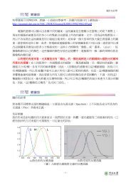
Figure <strong>22</strong>.8 Stress versus time<br />
for a reversed cycle in shear.