Chapter 22 Materials Selection and Design Considerations
Chapter 22 Materials Selection and Design Considerations
Chapter 22 Materials Selection and Design Considerations

Create successful ePaper yourself
Turn your PDF publications into a flip-book with our unique Google optimized e-Paper software.
Condition for<br />
nonpermanent spring<br />
deformation—shear<br />
yield strength <strong>and</strong> its<br />
relationship to shear<br />
modulus, number of<br />
effective coils, <strong>and</strong><br />
spring <strong>and</strong> wire<br />
diameters<br />
D<br />
2<br />
(a)<br />
<strong>22</strong>.5 Valve Spring <strong>Design</strong> <strong>and</strong> Material Requirements • W95<br />
where G is the shear modulus of the material from which the spring is constructed.<br />
Furthermore, dc may be computed from the total spring deflection, ds, <strong>and</strong> the<br />
number of effective spring coils, , as<br />
Now, solving for F in Equation <strong>22</strong>.14 gives<br />
D<br />
2<br />
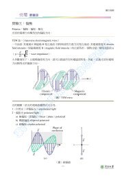
Figure <strong>22</strong>.5 Schematic diagrams of one coil of a helical spring, (a) prior to being<br />
compressed, <strong>and</strong> (b) showing the deflection dc produced from the compressive force F.<br />
(Adapted from K. Edwards <strong>and</strong> P. McKee, Fundamentals of Mechanical Component<br />
<strong>Design</strong>. Copyright © 1991 by McGraw-Hill, Inc. Reproduced with permission of The<br />
McGraw-Hill Companies.)<br />
d c � d s<br />
N c<br />
F � d4 d cG<br />
8D 3<br />
<strong>and</strong> substituting for F in Equation <strong>22</strong>.12 leads to<br />
t � d cGd<br />
pD 2 K w<br />
(<strong>22</strong>.15)<br />
(<strong>22</strong>.16)<br />
(<strong>22</strong>.17)<br />
Under normal circumstances, it is desired that a spring experience no permanent<br />
deformation upon loading; this means that the right-h<strong>and</strong> side of Equation <strong>22</strong>.17<br />
must be less than the shear yield strength of the spring material, or that<br />
t y 7 d cGd<br />
pD 2 K w<br />
(<strong>22</strong>.18)<br />
<strong>22</strong>.5 VALVE SPRING DESIGN AND MATERIAL<br />
REQUIREMENTS<br />
We shall now apply the results of the preceding section to an automobile valve<br />
spring.A cutaway schematic diagram of an automobile engine showing these springs<br />
is presented in Figure <strong>22</strong>.6. Functionally, springs of this type permit both intake <strong>and</strong><br />
exhaust valves to alternately open <strong>and</strong> close as the engine is in operation. Rotation<br />
of the camshaft causes a valve to open <strong>and</strong> its spring to be compressed, so that the<br />
load on the spring is increased. The stored energy in the spring then forces the<br />
valve to close as the camshaft continues its rotation. This process occurs for each<br />
valve for each engine cycle, <strong>and</strong> over the lifetime of the engine it occurs many millions<br />
of times. Furthermore, during normal engine operation, the temperature of<br />
the springs is approximately 80�C (175�F).<br />
N c<br />
t y<br />
�c<br />
F<br />
(b)<br />
D<br />
2