Chapter 22 Materials Selection and Design Considerations
Chapter 22 Materials Selection and Design Considerations
Chapter 22 Materials Selection and Design Considerations

Create successful ePaper yourself
Turn your PDF publications into a flip-book with our unique Google optimized e-Paper software.
<strong>Chapter</strong> <strong>22</strong> <strong>Materials</strong> <strong>Selection</strong> <strong>and</strong><br />
<strong>Design</strong> <strong>Considerations</strong><br />
Perhaps one of the most important tasks that an<br />
engineer may be called upon to perform is that of<br />
materials selection with regard to component design.<br />
Inappropriate or improper decisions can be disastrous<br />
from both economic <strong>and</strong> safety perspectives. There-<br />
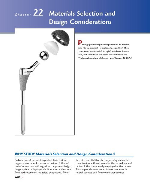
Photograph showing the components of an artificial<br />
total hip replacement (in exploded perspective). These<br />
components are (from left to right) as follows: femoral<br />
stem, ball, acetabular cup insert, <strong>and</strong> acetabular cup.<br />
(Photograph courtesy of Zimmer, Inc., Warsaw, IN, USA.)<br />
WHY STUDY <strong>Materials</strong> <strong>Selection</strong> <strong>and</strong> <strong>Design</strong> <strong>Considerations</strong>?<br />
W86 •<br />
fore, it is essential that the engineering student become<br />
familiar with <strong>and</strong> versed in the procedures <strong>and</strong><br />
protocols that are normally employed in this process.<br />
This chapter discusses materials selection issues in<br />
several contexts <strong>and</strong> from various perspectives.
Learning Objectives<br />
After careful study of this chapter you should be able to do the following:<br />
1. Describe how the strength performance index<br />
for a solid cylindrical shaft is determined.<br />
2. Describe the manner in which materials selection<br />
charts are employed in the materials selection<br />
process.<br />
3. Briefly describe the steps that are used to ascertain<br />
whether or not a particular metal alloy is<br />
suitable for use in an automobile valve spring.<br />
4. Briefly describe the difference in surface features<br />
(as observed in scanning electron micrographs)<br />
for a steel alloy that (a) experienced a ductile<br />
fracture, <strong>and</strong> (b) failed in a brittle manner.<br />
5. List <strong>and</strong> briefly explain six biocompatibility considerations<br />
relative to materials that are employed<br />
in artificial hip replacements.<br />
6. Name the four components found in the artificial<br />
hip replacement, <strong>and</strong>, for each, list its specific<br />
material requirements.<br />
7. Name <strong>and</strong> briefly define the two factors that<br />
are important to consider relative to the suitability<br />
of a material for use for chemical protective<br />
clothing.<br />
8. Describe the components <strong>and</strong> their functions for<br />
an integrated circuit leadframe.<br />
9. (a) Name <strong>and</strong> briefly describe the three<br />
processes that are carried out during integrated<br />
circuit packaging. (b) Note property requirements<br />
for each of these processes, <strong>and</strong>, in<br />
addition, cite at least two materials that are<br />
employed.<br />
<strong>22</strong>.1 INTRODUCTION<br />
Virtually the entire book to this point has dealt with the properties of various materials,<br />
how the properties of a specific material are dependent on its structure, <strong>and</strong>,<br />
in many cases, how structure may be fashioned by the processing technique that is<br />
employed during production. Of late, there has been a trend to emphasize the element<br />
of design in engineering pedagogy. To a materials scientist or materials engineer,<br />
design can be taken in several contexts. First of all, it can mean designing new<br />
materials having unique property combinations. Alternatively, design can involve<br />
selecting a new material having a better combination of characteristics for a specific<br />
application; choice of material cannot be made without consideration of necessary<br />
manufacturing processes (i.e., forming, welding, etc.), which also rely on material<br />
properties. Or, finally, design might mean developing a process for producing a<br />
material having better properties.<br />
One particularly effective technique for teaching design principles is the case<br />
study method. With this technique, the solutions to real-life engineering problems<br />
are carefully analyzed in detail so that the student may observe the procedures <strong>and</strong><br />
rationale that are involved in the decision-making process. We have chosen to perform<br />
six case studies, which draw upon principles that were introduced in previous<br />
chapters. Five of these studies involve materials that are used for the following: (1)<br />
a torsionally stressed cylindrical shaft (materials selection); (2) an automobile valve<br />
spring; (3) the artificial total hip replacement; (4) chemical protective clothing; <strong>and</strong><br />
(5) integrated circuit packages. The remaining case study discusses the probable<br />
cause of failure of an automobile rear axle.<br />
<strong>Materials</strong> <strong>Selection</strong> for a Torsionally<br />
Stressed Cylindrical Shaft<br />
We begin by addressing the design process from the perspective of materials<br />
selection; that is, for some application, selecting a material having a desirable<br />
or optimum property or combination of properties. Elements of this materials
W88 • <strong>Chapter</strong> <strong>22</strong> / <strong>Materials</strong> <strong>Selection</strong> <strong>and</strong> <strong>Design</strong> <strong>Considerations</strong><br />
selection process involve deciding on the constraints of the problem, <strong>and</strong>, from<br />
these, establishing criteria that can be used in materials selection to maximize<br />
performance.<br />
The component or structural element we have chosen to discuss is a solid cylindrical<br />
shaft that is subjected to a torsional stress. Strength of the shaft will be considered<br />
in detail, <strong>and</strong> criteria will be developed for the maximization of strength<br />
with respect to both minimum material mass <strong>and</strong> minimum cost. Other parameters<br />
<strong>and</strong> properties that may be important in this selection process are also discussed<br />
briefly.<br />
<strong>22</strong>.2 STRENGTH CONSIDERATIONS—<br />
TORSIONALLY STRESSED SHAFT<br />
For this portion of the design problem, we will establish a criterion for selection of<br />
light <strong>and</strong> strong materials for this shaft. It will be assumed that the twisting moment<br />
<strong>and</strong> length of the shaft are specified, whereas the radius (or cross-sectional<br />
area) may be varied. We develop an expression for the mass of material required<br />
in terms of twisting moment, shaft length, <strong>and</strong> density <strong>and</strong> strength of the material.<br />
Using this expression, it will be possible to evaluate the performance–that is, maximize<br />
the strength of this torsionally stressed shaft with respect to mass <strong>and</strong>, in<br />
addition, relative to material cost.<br />
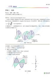
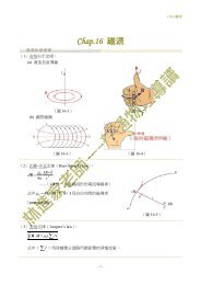
Consider the cylindrical shaft of length L <strong>and</strong> radius r, as shown in Figure <strong>22</strong>.1.<br />
The application of twisting moment (or torque) Mt produces an angle of twist f.<br />
Shear stress t at radius r is defined by the equation<br />
Here, J is the polar moment of inertia, which for a solid cylinder is<br />
Thus,<br />
t � M tr<br />
J<br />
J � pr4<br />
2<br />
t � 2M t<br />
pr 3<br />
(<strong>22</strong>.1)<br />
(<strong>22</strong>.2)<br />
(<strong>22</strong>.3)<br />
A safe design calls for the shaft to be able to sustain some twisting moment without<br />
fracture. In order to establish a materials selection criterion for a light <strong>and</strong> strong<br />
material, we replace the shear stress in Equation <strong>22</strong>.3 with the shear strength of the<br />
material divided by a factor of safety N, as<br />
tf (<strong>22</strong>.4)<br />
N � 2Mt pr 3<br />
tf M t<br />
L<br />
�<br />
r<br />
Figure <strong>22</strong>.1 A solid cylindrical shaft that<br />
experiences an angle of twist f in response to<br />
the application of a twisting moment Mt.
For a cylindrical<br />
shaft of length L <strong>and</strong><br />
radius r that is<br />
stressed in torsion,<br />
expression for mass<br />
in terms of density<br />
<strong>and</strong> shear strength of<br />
the shaft material<br />
Strength performance<br />
index expression for<br />
a torsionally stressed<br />
cylindrical shaft<br />
<strong>22</strong>.2 Strength <strong>Considerations</strong>—Torsionally Stressed Shaft • W89<br />
It is now necessary to take into consideration material mass. The mass m of any<br />
given quantity of material is just the product of its density <strong>and</strong> volume. Since<br />
the volume of a cylinder is just pr then<br />
2 (r)<br />
L,<br />
m � pr 2 Lr<br />
or, the radius of the shaft in terms of its mass is just<br />
m<br />
r �<br />
A pLr<br />
Substitution of this r expression into Equation <strong>22</strong>.4 leads to<br />
tf N �<br />
2Mt m<br />
p a<br />
A pLr b<br />
3<br />
pL<br />
� 2Mt B<br />
3r3 m3 Solving this expression for the mass m yields<br />
m � 12NM t2 2�3 1p 1�3 L2 a r<br />
(<strong>22</strong>.5)<br />
(<strong>22</strong>.6)<br />
(<strong>22</strong>.7)<br />
(<strong>22</strong>.8)<br />
The parameters on the right-h<strong>and</strong> side of this equation are grouped into three sets of<br />
parentheses.Those contained within the first set (i.e., N <strong>and</strong> ) relate to the safe functioning<br />
of the shaft.Within the second parentheses is L, a geometric parameter. Finally,<br />
the material properties of density <strong>and</strong> strength are contained within the last set.<br />
The upshot of Equation <strong>22</strong>.8 is that the best materials to be used for a light<br />
shaft that can safely sustain a specified twisting moment are those having low r�t<br />
ratios. In terms of material suitability, it is sometimes preferable to work with what<br />
is termed a performance index, P, which is just the reciprocal of this ratio; that is,<br />
2�3<br />
Mt f<br />
P � t2�3 f<br />
r<br />
t2�3 f<br />
(<strong>22</strong>.9)<br />
In this context we want to utilize a material having a large performance index.<br />
At this point it becomes necessary to examine the performance indices of a variety<br />
of potential materials. This procedure is expedited by the utilization of what<br />
are termed materials selection charts. 1 These are plots of the values of one material<br />
property versus those of another property. Both axes are scaled logarithmically <strong>and</strong><br />
usually span about five orders of magnitude, so as to include the properties of virtually<br />
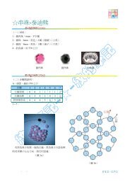
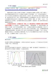
all materials. For example, for our problem, the chart of interest is logarithm<br />
of strength versus logarithm of density, which is shown in Figure <strong>22</strong>.2. 2 It may be<br />
noted on this plot that materials of a particular type (e.g., woods, engineering polymers,<br />
etc.) cluster together <strong>and</strong> are enclosed within an envelope delineated with a<br />
bold line. Subclasses within these clusters are enclosed using finer lines.<br />
1 A comprehensive collection of these charts may be found in M. F. Ashby, <strong>Materials</strong> <strong>Selection</strong><br />
in Mechanical <strong>Design</strong>, 2nd edition, Butterworth-Heinemann, Woburn, UK, 2002.<br />
2 Strength for metals <strong>and</strong> polymers is taken as yield strength, for ceramics <strong>and</strong> glasses, compressive<br />
strength, for elastomers, tear strength, <strong>and</strong> for composites, tensile failure strength.<br />
b
W90 • <strong>Chapter</strong> <strong>22</strong> / <strong>Materials</strong> <strong>Selection</strong> <strong>and</strong> <strong>Design</strong> <strong>Considerations</strong><br />
Strength (MPa)<br />
10,000<br />
1000<br />
100<br />
10<br />
1<br />
P = 100<br />
P = 30<br />
P = 10<br />
Cork<br />
P = 3<br />
Balsa<br />
Balsa<br />
Parallel<br />
to Grain<br />
Polymer<br />
foams<br />
Engineering<br />
composites<br />
Ash<br />
Oak<br />
Pine<br />
Fir<br />
Ash<br />
Woods Oak<br />
Pine<br />
Fir<br />
Perpendicular<br />
to Grain<br />
Wood<br />
Products<br />
LDPE<br />
Soft<br />
Butyl<br />
PP<br />
PS<br />
Engineering<br />
ceramics<br />
Nylons<br />
PMMA<br />
Glasses<br />
MEL<br />
PVC<br />
Epoxies<br />
Polyesters<br />
HDPE<br />
PTFE<br />
PU<br />
Silicone<br />
CFRP<br />
GFRP<br />
UNIPLY<br />
KFRP<br />
CFRPBe<br />
GFRP<br />
Laminates<br />
KFRP<br />
Elastomers<br />
0.1<br />
0.1 0.3 1 3 10 30<br />
B<br />
Si<br />
Mg<br />
Alloys<br />
Density (Mg /m 3 )<br />
Engineering<br />
polymers<br />
Porous<br />
ceramics<br />
Figure <strong>22</strong>.2 Strength-versus-density materials selection chart. <strong>Design</strong> guidelines for<br />
performance indices of 3, 10, 30, <strong>and</strong> 100 (MPa) 2�3 m 3 /Mg have been constructed, all having<br />
3<br />
a slope of 2. (Adapted from M. F. Ashby, <strong>Materials</strong> <strong>Selection</strong> in Mechanical <strong>Design</strong>.<br />
Copyright © 1992. Reprinted by permission of Butterworth-Heinemann Ltd.)<br />
Now, taking the logarithm of both sides of Equation <strong>22</strong>.9 <strong>and</strong> rearranging yields<br />
log t f � 3<br />
2 log r � 3<br />
2 log P<br />
Diamond<br />
Si3N4 Sialons<br />
Al2O3 ZrO2<br />
Cermets<br />
MgO<br />
Ge<br />
Engineering<br />
alloys<br />
(<strong>22</strong>.10)<br />
This expression tells us that a plot of log �f versus log will yield a family of straight<br />
<strong>and</strong> parallel lines all having a slope of each line in the family corresponds to a<br />
different performance index, P. These lines are termed design guidelines, <strong>and</strong> four<br />
have been included in Figure <strong>22</strong>.2 for P values of 3, 10, 30, <strong>and</strong> 100 (MPa)<br />
All materials that lie on one of these lines will perform equally well in terms of<br />
2�3<br />
r<br />
3<br />
2;<br />
3 m /Mg.<br />
SiC<br />
Pottery Ti<br />
Alloys<br />
Cement<br />
Concrete<br />
Al Alloys<br />
Stone,<br />
Rock<br />
Engineering<br />
alloys<br />
Steels<br />
Cast<br />
Irons<br />
Zn<br />
Alloys<br />
Lead<br />
Alloys<br />
Ni Alloys<br />
Cu Alloys<br />
W Alloys<br />
Mo Alloys
Strength (MPa)<br />
10,000<br />
1000<br />
100<br />
10<br />
1<br />
300 MPa<br />
P = 10<br />
Balsa<br />
(MPa) 2/3 m 3 /Mg<br />
Cork<br />
<strong>22</strong>.2 Strength <strong>Considerations</strong>—Torsionally Stressed Shaft • W91<br />
strength-per-mass basis; materials whose positions lie above a particular line will<br />
have higher performance indices, while those lying below will exhibit poorer performances.<br />
For example, a material on the line will yield the same strength<br />
with one-third the mass as another material that lies along the line.<br />
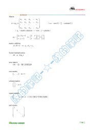
The selection process now involves choosing one of these lines, a “selection<br />
line” that includes some subset of these materials; for the sake of argument let us<br />
pick P � 10 (MPa) which is represented in Figure <strong>22</strong>.3. <strong>Materials</strong> lying<br />
2�3<br />
P � 30<br />
P � 10<br />
3 m /Mg,<br />
Balsa<br />
Parallel<br />
to Grain<br />
Ash<br />
Oak<br />
Pine<br />
Fir<br />
Polymer<br />
foams<br />
Engineering<br />
composites<br />
Wood<br />
Products<br />
Ash<br />
Woods Oak<br />
Pine<br />
Fir<br />
Perpendicular<br />
to Grain<br />
LDPE<br />
Soft<br />
Butyl<br />
PP<br />
PS<br />
Glasses<br />
CFRP<br />
GFRP<br />
UNIPLY<br />
KFRP<br />
CFRPBe<br />
GFRP<br />
Laminates<br />
KFRP<br />
Nylons<br />
PMMA<br />
MEL<br />
PVC<br />
Epoxies<br />
Polyesters<br />
HDPE<br />
PTFE<br />
PU<br />
Silicone<br />
Engineering<br />
ceramics<br />
Pottery<br />
Mg<br />
Alloys<br />
Elastomers<br />
B<br />
Si<br />
SiC<br />
Cement<br />
Concrete<br />
Engineering<br />
polymers<br />
Diamond<br />
Si3N4 Sialons<br />
Al2O3 ZrO2<br />
Cermets<br />
MgO<br />
Ge<br />
Ti<br />
Alloys<br />
Al Alloys<br />
Stone,<br />
Rock<br />
Engineering<br />
alloys<br />
Porous<br />
ceramics<br />
Steels<br />
Cast<br />
Irons<br />
Zn<br />
Alloys<br />
Lead<br />
Alloys<br />
Ni Alloys<br />
Cu Alloys<br />
Engineering<br />
alloys<br />
W Alloys<br />
Mo Alloys<br />
0.1<br />
0.1 0.3 1 3 10 30<br />
Density (Mg /m 3 )<br />
Figure <strong>22</strong>.3 Strength-versus-density materials selection chart. Those materials lying within<br />
the shaded region are acceptable c<strong>and</strong>idates for a solid cylindrical shaft that has a massstrength<br />
performance index in excess of 10 (MPa) <strong>and</strong> a strength of at least<br />
300 MPa (43,500 psi). (Adapted from M. F. Ashby, <strong>Materials</strong> <strong>Selection</strong> in Mechanical<br />
<strong>Design</strong>. Copyright © 1992. Reprinted by permission of Butterworth-Heinemann Ltd.)<br />
2�3 3<br />
m /Mg,
W92 • <strong>Chapter</strong> <strong>22</strong> / <strong>Materials</strong> <strong>Selection</strong> <strong>and</strong> <strong>Design</strong> <strong>Considerations</strong><br />
along this line or above it are in the “search region” of the diagram <strong>and</strong> are possible<br />
c<strong>and</strong>idates for this rotating shaft. These include wood products, some plastics, a<br />
number of engineering alloys, the engineering composites, <strong>and</strong> glasses <strong>and</strong> engineering<br />
ceramics. On the basis of fracture toughness considerations, the engineering<br />
ceramics <strong>and</strong> glasses are ruled out as possibilities.<br />
Let us now impose a further constraint on the problem—namely, that the<br />
strength of the shaft must equal or exceed 300 MPa (43,500 psi). This may be represented<br />
on the materials selection chart by a horizontal line constructed at 300 MPa,<br />
Figure <strong>22</strong>.3. Now the search region is further restricted to that area above both of<br />
these lines. Thus, all wood products, all engineering polymers, other engineering alloys<br />
(viz. Mg <strong>and</strong> some Al alloys), as well as some engineering composites are eliminated<br />
as c<strong>and</strong>idates; steels, titanium alloys, high-strength aluminum alloys, <strong>and</strong> the<br />
engineering composites remain as possibilities.<br />
At this point we are in a position to evaluate <strong>and</strong> compare the strength performance<br />
behavior of specific materials. Table <strong>22</strong>.1 presents the density, strength,<br />
<strong>and</strong> strength performance index for three engineering alloys <strong>and</strong> two engineering<br />
composites, which were deemed acceptable c<strong>and</strong>idates from the analysis using the<br />
materials selection chart. In this table, strength was taken as 0.6 times the tensile<br />
yield strength (for the alloys) <strong>and</strong> 0.6 times the tensile strength (for the composites);<br />
these approximations were necessary since we are concerned with strength in<br />
torsion <strong>and</strong> torsional strengths are not readily available. Furthermore, for the two<br />
engineering composites, it is assumed that the continuous <strong>and</strong> aligned glass <strong>and</strong> car-<br />
bon fibers are wound in a helical fashion (Figure 16.15), <strong>and</strong> at a 45� angle refer-<br />
enced to the shaft axis. The five materials in Table <strong>22</strong>.1 are ranked according to<br />
strength performance index, from highest to lowest: carbon fiber-reinforced <strong>and</strong><br />
glass fiber-reinforced composites, followed by aluminum, titanium, <strong>and</strong> 4340 steel<br />
alloys.<br />
Material cost is another important consideration in the selection process. In<br />
real-life engineering situations, economics of the application often is the overriding<br />
issue <strong>and</strong> normally will dictate the material of choice. One way to determine material<br />
cost is by taking the product of the price (on a per-unit mass basis) <strong>and</strong> the<br />
required mass of material.<br />
Cost considerations for these five remaining c<strong>and</strong>idate materials—steel, aluminum,<br />
<strong>and</strong> titanium alloys, <strong>and</strong> two engineering composites—are presented in<br />
Table <strong>22</strong>.1 Density (�), Strength (� f), <strong>and</strong> Performance Index (P) for<br />
Five Engineering <strong>Materials</strong><br />
Material<br />
�<br />
(Mg/m<br />
�f 2�3<br />
�f /� � P<br />
3 ) (MPa) [(MPa) 2�3 m 3 /Mg]<br />
Carbon fiber-reinforced composite<br />
(0.65 fiber fraction)<br />
1.5 1140 72.8<br />
a<br />
Glass fiber-reinforced composite<br />
(0.65 fiber fraction)<br />
2.0 1060 52.0<br />
a<br />
Aluminum alloy (2024-T6) 2.8 300 16.0<br />
Titanium alloy (Ti-6Al-4V) 4.4 525 14.8<br />
4340 Steel (oil-quenched<br />
<strong>and</strong> tempered)<br />
7.8 780 10.9<br />
a<br />
The fibers in these composites are continuous, aligned, <strong>and</strong> wound in a helical fashion at<br />
a 45�<br />
angle relative to the shaft axis.
<strong>22</strong>.3 Other Property <strong>Considerations</strong> <strong>and</strong> the Final Decision • W93<br />
2/3 — 2/3<br />
Table <strong>22</strong>.2 Tabulation of the �/�f Ratio, Relative Cost (c ), <strong>and</strong> the Product of �/�f <strong>and</strong><br />
— a<br />
c for Five Engineering <strong>Materials</strong><br />
2�3<br />
���f Material [10 �2 {Mg�(MPa) 2�3 m 3 }] ($�$) [10 �2 ($�$){Mg�(MPa) 2�3 m 3 }]<br />
Table <strong>22</strong>.2. In the first column is tabulated The next column lists the approximate<br />
relative cost, denoted as this parameter is simply the per-unit mass<br />
cost of material divided by the per-unit mass cost for low-carbon steel, one of the<br />
common engineering materials. The underlying rationale for using is that while<br />
the price of a specific material will vary over time, the price ratio between that<br />
material <strong>and</strong> another will, most likely, change more slowly.<br />
Finally, the right-h<strong>and</strong> column of Table <strong>22</strong>.2 shows the product of <strong>and</strong><br />
This product provides a comparison of these several materials on the basis of the cost<br />
of materials for a cylindrical shaft that would not fracture in response to the twisting<br />
moment We use this product inasmuch as r�t is proportional to the mass of<br />
material required (Equation <strong>22</strong>.8) <strong>and</strong> c is the relative cost on a per-unit mass basis.<br />
Now the most economical is the 4340 steel, followed by the glass fiber-reinforced<br />
composite, 2024-T6 aluminum, the carbon fiber-reinforced composite, <strong>and</strong> the titanium<br />
alloy. Thus, when the issue of economics is considered, there is a significant<br />
alteration within the ranking scheme. For example, inasmuch as the carbon fiberreinforced<br />
composite is relatively expensive, it is significantly less desirable; in other<br />
words, the higher cost of this material may not outweigh the enhanced strength it<br />
provides.<br />
2�3<br />
r�t c.<br />
Mt. f<br />
2�3<br />
r�t<br />
c;<br />
c<br />
f<br />
2�3<br />
f .<br />
<strong>22</strong>.3 OTHER PROPERTY CONSIDERATIONS AND<br />
THE FINAL DECISION<br />
To this point in our materials selection process we have considered only the strength<br />
of materials. Other properties relative to the performance of the cylindrical shaft<br />
may be important—for example, stiffness, <strong>and</strong>, if the shaft rotates, fatigue behavior<br />
(Sections 8.7 <strong>and</strong> 8.8). Furthermore, fabrication costs should also be considered; in<br />
our analysis they have been neglected.<br />
Relative to stiffness, a stiffness-to-mass performance analysis similar to that<br />
above could be conducted. For this case, the stiffness performance index is<br />
P s � 1G<br />
r<br />
(<strong>22</strong>.11)<br />
where G is the shear modulus. The appropriate materials selection chart (log G<br />
versus log r)<br />
would be used in the preliminary selection process. Subsequently,<br />
performance index <strong>and</strong> per-unit-mass cost data would be collected on specific<br />
–<br />
c<br />
– 2�3<br />
c(���f<br />
)<br />
4340 Steel (oil-quenched<br />
<strong>and</strong> tempered)<br />
9.2 5 46<br />
Glass fiber-reinforced composite<br />
(0.65 fiber fraction)<br />
1.9 40 76<br />
b<br />
Aluminum alloy (2024-T6) 6.2 15 93<br />
Carbon fiber-reinforced composite<br />
(0.65 fiber fraction)<br />
1.4 80 112<br />
b<br />
Titanium alloy (Ti-6Al-4V) 6.8 110 748<br />
a<br />
The relative cost is the ratio of the price per-unit mass of the material <strong>and</strong> low-carbon steel.<br />
b<br />
The fibers in these composites are continuous, aligned, <strong>and</strong> wound in a helical fashion at a 45�<br />
angle relative to<br />
the shaft axis.<br />
P s
W94 • <strong>Chapter</strong> <strong>22</strong> / <strong>Materials</strong> <strong>Selection</strong> <strong>and</strong> <strong>Design</strong> <strong>Considerations</strong><br />
c<strong>and</strong>idate materials; from these analyses the materials would be ranked on the basis<br />
of stiffness performance <strong>and</strong> cost.<br />
In deciding on the best material, it may be worthwhile to make a table employing<br />
the results of the various criteria that were used. The tabulation would include,<br />
for all c<strong>and</strong>idate materials, performance index, cost, etc. for each criterion, as<br />
well as comments relative to any other important considerations. This table puts in<br />
perspective the important issues <strong>and</strong> facilitates the final decision process.<br />
Automobile Valve Spring<br />
<strong>22</strong>.4 MECHANICS OF SPRING DEFORMATION<br />
The basic function of a spring is to store mechanical energy as it is initially elastically<br />
deformed <strong>and</strong> then recoup this energy at a later time as the spring recoils. In<br />
this section helical springs that are used in mattresses <strong>and</strong> in retractable pens <strong>and</strong><br />
as suspension springs in automobiles are discussed. A stress analysis will be conducted<br />
on this type of spring, <strong>and</strong> the results will then be applied to a valve spring<br />
that is utilized in automobile engines.<br />
Consider the helical spring shown in Figure <strong>22</strong>.4, which has been constructed<br />
of wire having a circular cross section of diameter d; the coil center-to-center diameter<br />
is denoted as D. The application of a compressive force F causes a twisting<br />
force, or moment, denoted T, as shown in the figure.A combination of shear stresses<br />
result, the sum of which, t, is<br />
t � 8FD<br />
pd 3 K w<br />
where Kw is a force-independent constant that is a function of the D�d ratio:<br />
Kw � 1.60 a D<br />
d b<br />
�0.140<br />
(<strong>22</strong>.12)<br />
(<strong>22</strong>.13)<br />
In response to the force F, the coiled spring will experience deflection, which<br />
will be assumed to be totally elastic. The amount of deflection per coil of spring, dc, as indicated in Figure <strong>22</strong>.5, is given by the expression<br />
F<br />
D<br />
F<br />
T<br />
d c � 8FD3<br />
d 4 G<br />
d<br />
(<strong>22</strong>.14)<br />
Figure <strong>22</strong>.4 Schematic<br />
diagram of a helical spring<br />
showing the twisting moment<br />
T that results from the<br />
compressive force F. (Adapted<br />
from K. Edwards <strong>and</strong> P.<br />
McKee, Fundamentals of<br />
Mechanical Component <strong>Design</strong>.<br />
Copyright ©<br />
1991 by McGraw-<br />
Hill, Inc. Reproduced with<br />
permission of The McGraw-<br />
Hill Companies.)
Condition for<br />
nonpermanent spring<br />
deformation—shear<br />
yield strength <strong>and</strong> its<br />
relationship to shear<br />
modulus, number of<br />
effective coils, <strong>and</strong><br />
spring <strong>and</strong> wire<br />
diameters<br />
D<br />
2<br />
(a)<br />
<strong>22</strong>.5 Valve Spring <strong>Design</strong> <strong>and</strong> Material Requirements • W95<br />
where G is the shear modulus of the material from which the spring is constructed.<br />
Furthermore, dc may be computed from the total spring deflection, ds, <strong>and</strong> the<br />
number of effective spring coils, , as<br />
Now, solving for F in Equation <strong>22</strong>.14 gives<br />
D<br />
2<br />
Figure <strong>22</strong>.5 Schematic diagrams of one coil of a helical spring, (a) prior to being<br />
compressed, <strong>and</strong> (b) showing the deflection dc produced from the compressive force F.<br />
(Adapted from K. Edwards <strong>and</strong> P. McKee, Fundamentals of Mechanical Component<br />
<strong>Design</strong>. Copyright © 1991 by McGraw-Hill, Inc. Reproduced with permission of The<br />
McGraw-Hill Companies.)<br />
d c � d s<br />
N c<br />
F � d4 d cG<br />
8D 3<br />
<strong>and</strong> substituting for F in Equation <strong>22</strong>.12 leads to<br />
t � d cGd<br />
pD 2 K w<br />
(<strong>22</strong>.15)<br />
(<strong>22</strong>.16)<br />
(<strong>22</strong>.17)<br />
Under normal circumstances, it is desired that a spring experience no permanent<br />
deformation upon loading; this means that the right-h<strong>and</strong> side of Equation <strong>22</strong>.17<br />
must be less than the shear yield strength of the spring material, or that<br />
t y 7 d cGd<br />
pD 2 K w<br />
(<strong>22</strong>.18)<br />
<strong>22</strong>.5 VALVE SPRING DESIGN AND MATERIAL<br />
REQUIREMENTS<br />
We shall now apply the results of the preceding section to an automobile valve<br />
spring.A cutaway schematic diagram of an automobile engine showing these springs<br />
is presented in Figure <strong>22</strong>.6. Functionally, springs of this type permit both intake <strong>and</strong><br />
exhaust valves to alternately open <strong>and</strong> close as the engine is in operation. Rotation<br />
of the camshaft causes a valve to open <strong>and</strong> its spring to be compressed, so that the<br />
load on the spring is increased. The stored energy in the spring then forces the<br />
valve to close as the camshaft continues its rotation. This process occurs for each<br />
valve for each engine cycle, <strong>and</strong> over the lifetime of the engine it occurs many millions<br />
of times. Furthermore, during normal engine operation, the temperature of<br />
the springs is approximately 80�C (175�F).<br />
N c<br />
t y<br />
�c<br />
F<br />
(b)<br />
D<br />
2
W96 • <strong>Chapter</strong> <strong>22</strong> / <strong>Materials</strong> <strong>Selection</strong> <strong>and</strong> <strong>Design</strong> <strong>Considerations</strong><br />
Valve<br />
spring<br />
Intake<br />
valve<br />
Crankshaft<br />
Cam<br />
Camshaft<br />
Exhaust<br />
valve<br />
Piston<br />
Figure <strong>22</strong>.6 Cutaway drawing of a<br />
section of an automobile engine in<br />
which various components including<br />
valves <strong>and</strong> valve springs are shown.<br />
A photograph of a typical valve spring is shown in Figure <strong>22</strong>.7. The spring<br />
has a total length of 1.67 in. (42 mm), is constructed of wire having a diameter d of<br />
0.170 in. (4.3 mm), has six coils (only four of which are active), <strong>and</strong> has a center-tocenter<br />
diameter D of 1.062 in. (27 mm). Furthermore, when installed <strong>and</strong> when a<br />
valve is completely closed, its spring is compressed a total of 0.24 in. (6.1 mm),<br />
Figure <strong>22</strong>.7 Photograph of a typical automobile valve<br />
spring.
<strong>22</strong>.5 Valve Spring <strong>Design</strong> <strong>and</strong> Material Requirements • W97<br />
which, from Equation <strong>22</strong>.15, gives an installed deflection per coil of<br />
d ic �<br />
� 0.060 in./coil (1.5 mm/coil)<br />
The cam lift is 0.30 in. (7.6 mm), which means that when the cam completely opens a<br />
valve, the spring experiences a maximum total deflection equal to the sum of the valve<br />
lift <strong>and</strong> the compressed deflection, namely, 0.30 in. � 0.24 in. � 0.54 in. (13.7 mm).<br />
Hence, the maximum deflection per coil, is<br />
d mc �<br />
0.24 in.<br />
4 coils<br />
0.54 in.<br />
4 coils<br />
d mc,<br />
� 0.135 in./coil (3.4 mm/coil)<br />
Thus, we have available all of the parameters in Equation <strong>22</strong>.18 (taking ),<br />
except for the required shear yield strength of the spring material.<br />
However, the material parameter of interest is really not inasmuch as the<br />
spring is continually stress cycled as the valve opens <strong>and</strong> closes during engine<br />
operation; this necessitates designing against the possibility of failure by fatigue<br />
rather than against the possibility of yielding. This fatigue complication is h<strong>and</strong>led<br />
by choosing a metal alloy that has a fatigue limit (Figure 8.19a) that is greater<br />
than the cyclic stress amplitude to which the spring will be subjected. For this<br />
reason, steel alloys, which have fatigue limits, are normally employed for valve<br />
springs.<br />
When using steel alloys in spring design, two assumptions may be made if the<br />
stress cycle is reversed (if where is the mean stress, or, equivalently, if<br />
in accordance with Equation 8.14 <strong>and</strong> as noted in Figure <strong>22</strong>.8). The<br />
first of these assumptions is that the fatigue limit of the alloy (expressed as stress<br />
amplitude) is 45,000 psi (310 MPa), the threshold of which occurs at about cycles.<br />
Secondly, for torsion <strong>and</strong> on the basis of experimental data, it has been found<br />
that the fatigue strength at cycles is 0.67TS, where TS is the tensile strength of<br />
the material (as measured from a pure tension test). The S–N fatigue diagram (i.e.,<br />
stress amplitude versus logarithm of the number of cycles to failure) for these alloys<br />
is shown in Figure <strong>22</strong>.9.<br />
Now let us estimate the number of cycles to which a typical valve spring may<br />
be subjected in order to determine whether it is permissible to operate within the<br />
fatigue limit regime of Figure <strong>22</strong>.9 (i.e., if the number of cycles exceeds 10 ). For<br />
the sake of argument, assume that the automobile in which the spring is mounted<br />
travels a minimum of 100,000 miles (161,000 km) at an average speed of 40 mph<br />
(64.4 km/h), with an average engine speed of 3000 rpm (rev/min). The total time<br />
it takes the automobile to travel this distance is 2500 h (100,000 mi/40 mph), or<br />
6<br />
103 106 dc � dmc ty, ty tm � 0, tm tmax ��tmin, �<br />
0<br />
Stress max<br />
�min<br />
Time<br />
d ic<br />
Figure <strong>22</strong>.8 Stress versus time<br />
for a reversed cycle in shear.
W98 • <strong>Chapter</strong> <strong>22</strong> / <strong>Materials</strong> <strong>Selection</strong> <strong>and</strong> <strong>Design</strong> <strong>Considerations</strong><br />
Goodman’s law—<br />
computation of the<br />
nonzero-mean-stress<br />
fatigue limit for a<br />
material using<br />
tensile strength <strong>and</strong><br />
zero-mean-stress<br />
fatigue limit values<br />
150,000 min. At 3000 rpm, the total number of revolutions is (3000 rev/min)(150,000<br />
min) rev, <strong>and</strong> since there are 2 rev/cycle, the total number of cycles is<br />
This result means that we may use the fatigue limit as the design stress<br />
inasmuch as the limit cycle threshold has been exceeded for the 100,000-mile<br />
distance of travel (i.e., since cycles 7 10 cycles).<br />
Furthermore, this problem is complicated by the fact that the stress cycle is<br />
not completely reversed (i.e., tm � 0)<br />
inasmuch as between minimum <strong>and</strong> maximum<br />
deflections the spring remains in compression; thus, the 45,000 psi (310 MPa)<br />
fatigue limit is not valid. What we would now like to do is first to make an appropriate<br />
extrapolation of the fatigue limit for this tm � 0 case <strong>and</strong> then compute<br />
<strong>and</strong> compare with this limit the actual stress amplitude for the spring; if the stress<br />
amplitude is significantly below the extrapolated limit, then the spring design is<br />
satisfactory.<br />
A reasonable extrapolation of the fatigue limit for this tm � 0 situation may be<br />
made using the following expression (termed Goodman’s law):<br />
6<br />
2.25 � 108 2.25 � 108 � 4.5 � 10<br />
.<br />
8<br />
t al � t e a1 � t m<br />
0.67TS b<br />
(<strong>22</strong>.19)<br />
where tal is the fatigue limit for the mean stress tm; te is the fatigue limit for<br />
tm � 0 [i.e., 45,000 psi (310 MPa)]; <strong>and</strong>, again, TS is the tensile strength of the<br />
alloy. To determine the new fatigue limit tal from the above expression necessitates<br />
the computation of both the tensile strength of the alloy <strong>and</strong> the mean stress<br />
for the spring.<br />
<strong>22</strong>.6 ONE COMMONLY EMPLOYED STEEL ALLOY<br />
One common spring alloy is an ASTM 232 chrome–vanadium steel, having a composition<br />
of 0.48–0.53 wt% C, 0.80–1.10 wt% Cr, a minimum of 0.15 wt% V, <strong>and</strong> the<br />
balance being Fe. Spring wire is normally cold drawn (Section 11.4) to the desired<br />
diameter; consequently, tensile strength will increase with the amount of drawing<br />
For an ASTM 232<br />
steel wire,<br />
dependence of<br />
tensile strength on<br />
drawn wire diameter<br />
45,000 psi<br />
Stress amplitude, S<br />
10 3<br />
0.67TS<br />
10 5<br />
Cycles to failure, N<br />
(logarithmic scale)<br />
10 7<br />
(i.e., with decreasing diameter). For this alloy it has been experimentally verified<br />
that, for the diameter d in inches, the tensile strength is<br />
TS 1psi2 � 169,0001d2 �0.167<br />
10 9<br />
Figure <strong>22</strong>.9 Shear<br />
stress amplitude versus<br />
logarithm of the number<br />
of cycles to fatigue failure<br />
for typical ferrous alloys.<br />
(<strong>22</strong>.20)
Since d � 0.170<br />
in. for this spring,<br />
<strong>22</strong>.6 One Commonly Employed Steel Alloy • W99<br />
Computation of the mean stress tm is made using Equation 8.14 modified to<br />
the shear stress situation as follows:<br />
(<strong>22</strong>.21)<br />
It now becomes necessary to determine the minimum <strong>and</strong> maximum shear stresses<br />
for the spring, using Equation <strong>22</strong>.17.The value of may be calculated from Equations<br />
<strong>22</strong>.17 <strong>and</strong> <strong>22</strong>.13 inasmuch as the minimum is known (i.e., in.). A<br />
shear modulus of 11.5 � 10 psi (79 GPa) will be assumed for the steel; this is the<br />
room-temperature value, which is also valid at the 80�C service temperature. Thus,<br />
is just<br />
6<br />
tmin dc dic � 0.060<br />
t min<br />
Now may be determined taking dc � dmc � 0.135 in. as follows:<br />
t max<br />
t min � d icGd<br />
pD 2 K w<br />
� dicGd c 1.60 aD<br />
2 pD d b<br />
�0.140<br />
d<br />
� c 10.060 in.2111.5 � 106 psi210.170 in.2<br />
p11.062 in.2 2<br />
� 41,000 psi 1280 MPa2<br />
tmax � dmcGd c 1.60 aD<br />
2 pD d b<br />
�0.140<br />
d<br />
� c 10.135 in.2111.5 � 106 psi210.170 in.2<br />
p11.062 in.2 2<br />
� 92,200 psi 1635 MPa2<br />
Now, from Equation <strong>22</strong>.21,<br />
t m � t min � t max<br />
2<br />
TS � 1169,000210.170 in.2 �0.167<br />
� <strong>22</strong>7,200 psi 11570 MPa2<br />
t m � t min � t max<br />
2<br />
41,000 psi � 92,200 psi<br />
� � 66,600 psi 1460 MPa2<br />
2<br />
(<strong>22</strong>.<strong>22</strong>a)<br />
(<strong>22</strong>.<strong>22</strong>b)<br />
The variation of shear stress with time for this valve spring is noted in Figure <strong>22</strong>.10;<br />
the time axis is not scaled, inasmuch as the time scale will depend on engine speed.<br />
Our next objective is to determine the fatigue limit amplitude (tal) for this<br />
tm � 66,600 psi (460 MPa) using Equation <strong>22</strong>.19 <strong>and</strong> for te <strong>and</strong> TS values of<br />
45,000 psi (310 MPa) <strong>and</strong> <strong>22</strong>7,200 psi (1570 MPa), respectively. Thus,<br />
66,600 psi<br />
� 145,000 psi2c1 �<br />
10.6721<strong>22</strong>7,200 psi2<br />
� 25,300 psi 1175 MPa2<br />
d<br />
tal � te c 1 � tm 0.67TS d<br />
1.062 in.<br />
dc1.60 a<br />
0.170 in. b<br />
�0.140<br />
d<br />
1.062 in.<br />
dc1.60 a<br />
0.170 in. b<br />
�0.140<br />
d
W100 • <strong>Chapter</strong> <strong>22</strong> / <strong>Materials</strong> <strong>Selection</strong> <strong>and</strong> <strong>Design</strong> <strong>Considerations</strong><br />
Stress (10 3 psi)<br />
100<br />
80<br />
60<br />
40<br />
20<br />
0<br />
� max = 92,200 psi<br />
� aa = 25,600 psi<br />
� min = 41,000 psi<br />
Time<br />
� m = 66,600 psi<br />
Figure <strong>22</strong>.10 Shear stress<br />
versus time for an automobile<br />
valve spring.<br />
Now let us determine the actual stress amplitude for the valve spring using<br />
Equation 8.16 modified to the shear stress condition:<br />
taa �<br />
92,200 psi � 41,000 psi<br />
� � 25,600 psi 1177 MPa2<br />
2<br />
tmax � tmin 2<br />
(<strong>22</strong>.23)<br />
Thus, the actual stress amplitude is slightly greater than the fatigue limit, which<br />
means that this spring design is marginal.<br />
The fatigue limit of this alloy may be increased to greater than 25,300 psi<br />
(175 MPa) by shot peening, a procedure described in Section 8.10. Shot peening<br />
involves the introduction of residual compressive surface stresses by plastically<br />
deforming outer surface regions; small <strong>and</strong> very hard particles are projected onto<br />
the surface at high velocities. This is an automated procedure commonly used<br />
to improve the fatigue resistance of valve springs; in fact, the spring shown in<br />
Figure <strong>22</strong>.7 has been shot peened, which accounts for its rough surface texture.<br />
Shot peening has been observed to increase the fatigue limit of steel alloys in<br />
excess of 50% <strong>and</strong>, in addition, to reduce significantly the degree of scatter of<br />
fatigue data.<br />
This spring design, including shot peening, may be satisfactory; however, its adequacy<br />
should be verified by experimental testing.The testing procedure is relatively<br />
complicated <strong>and</strong>, consequently, will not be discussed in detail. In essence, it involves<br />
performing a relatively large number of fatigue tests (on the order of 1000) on this<br />
shot-peened ASTM 232 steel, in shear, using a mean stress of 66,600 psi (460 MPa)<br />
<strong>and</strong> a stress amplitude of 25,600 psi (177 MPa), <strong>and</strong> for 10 cycles. On the basis of<br />
6<br />
the number of failures, an estimate of the survival probability can be made. For the<br />
sake of argument, let us assume that this probability turns out to be 0.99999; this<br />
means that one spring in 100,000 produced will fail.<br />
Suppose that you are employed by one of the large automobile companies that<br />
manufactures on the order of 1 million cars per year, <strong>and</strong> that the engine powering<br />
each automobile is a six-cylinder one. Since for each cylinder there are two valves,<br />
<strong>and</strong> thus two valve springs, a total of 12 million springs would be produced every<br />
year. For the above survival probability rate, the total number of spring failures<br />
would be approximately 120, which also corresponds to 120 engine failures. As a<br />
t aa
<strong>22</strong>.7 Introduction • W101<br />
practical matter, one would have to weigh the cost of replacing these 120 engines<br />
against the cost of a spring redesign.<br />
Redesign options would involve taking measures to reduce the shear stresses<br />
on the spring, by altering the parameters in Equations <strong>22</strong>.13 <strong>and</strong> <strong>22</strong>.17. This would<br />
include either (1) increasing the coil diameter D, which would also necessitate<br />
increasing the wire diameter d, or (2) increasing the number of coils Nc. Failure of an Automobile<br />
Rear Axle 3<br />
<strong>22</strong>.7 INTRODUCTION<br />
Subsequent to an accident in which a light pickup truck left the road <strong>and</strong> overturned,<br />
it was noted that one of the rear axles had failed at a point near the wheel<br />
mounting flange. This axle was made of a steel that contained approximately<br />
0.3 wt% C. Furthermore, the other axle was intact <strong>and</strong> did not experience fracture.<br />
An investigation was carried out to determine whether the axle failure caused the<br />
accident or whether the failure occurred as a consequence of the accident.<br />
Figure <strong>22</strong>.11 is a schematic diagram that shows the components of a rear axle assembly<br />
of the type used in this pickup truck. The fracture occurred adjacent to the<br />
bearing lock nut, as noted in this schematic. A photograph of one end of the failed<br />
axle shaft is presented in Figure <strong>22</strong>.12a, <strong>and</strong> Figure <strong>22</strong>.12b is an enlarged view of the<br />
other fractured piece that includes the wheel mounting flange <strong>and</strong> the stub end of the<br />
failed axle. Here (Figure <strong>22</strong>.12b) note that a keyway was present in the area of failure;<br />
furthermore, threads for the lock nut were also situated adjacent to this keyway.<br />
Axle shaft<br />
Gasket<br />
Gasket<br />
Wheel bearing<br />
Wheel bearing retainer<br />
Point of failure<br />
Axle shaft seal<br />
Figure <strong>22</strong>.11 Schematic diagram showing typical components of a light truck axle, <strong>and</strong><br />
the fracture site for the failed axle of this case study. (Reproduced from MOTOR Auto<br />
Repair Manual, 39th Edition © Copyright 1975. By permission of the Hearst Corporation.)<br />
3 This case study was taken from Lawrence Kashar, “Effect of Strain Rate on the Failure<br />
Mode of a Rear Axle,” H<strong>and</strong>book of Case Histories in Failure Analysis, Vol. 1, pp. 74–78,<br />
ASM International, <strong>Materials</strong> Park, OH, 1992.
W102 • <strong>Chapter</strong> <strong>22</strong> / <strong>Materials</strong> <strong>Selection</strong> <strong>and</strong> <strong>Design</strong> <strong>Considerations</strong><br />
(a) (b)<br />
Figure <strong>22</strong>.12 (a) Photograph of one section of the failed axle. (b) Photograph showing<br />
wheel mounting flange <strong>and</strong> stub end of failed axle. [Reproduced with permission from<br />
H<strong>and</strong>book of Case Studies in Failure Analysis, Vol. 1 (1992), ASM International, <strong>Materials</strong><br />
Park, OH, 44073-0002.]<br />
Upon examination of the fracture surface it was noted that the region corresponding<br />
to the outside shaft perimeter [being approximately 6.4 mm (0.25 in.)<br />
wide] was very flat; furthermore, the center region was rough in appearance.<br />
<strong>22</strong>.8 TESTING PROCEDURE AND RESULTS<br />
Details of the fracture surface in the vicinity of the keyway are shown in the photograph<br />
of Figure <strong>22</strong>.13; note that the keyway appears at the bottom of the photograph.<br />
Both the flat outer perimeter <strong>and</strong> rough interior regions may be observed<br />
in the photograph. There are chevron patterns that emanate inward from the corners<br />
of <strong>and</strong> parallel to the sides of the keyway; these are barely discernable in the<br />
photograph, but indicate the direction of crack propagation.<br />
Fractographic analyses were also conducted on the fracture surface. Figure <strong>22</strong>.14<br />
shows a scanning electron micrograph taken near one of the keyway corners.<br />
Cleavage features may be noted in this micrograph, whereas any evidence of dimples<br />
Figure <strong>22</strong>.13 Optical<br />
micrograph of failed<br />
section of axle that<br />
shows the keyway<br />
(bottom), as well as the<br />
flat outer perimeter <strong>and</strong><br />
rough core regions.<br />
[Reproduced with<br />
permission from<br />
H<strong>and</strong>book of Case<br />
Studies in Failure<br />
Analysis, Vol. 1 (1992),<br />
ASM International,<br />
<strong>Materials</strong> Park, OH,<br />
44073-0002.]
<strong>22</strong>.8 Testing Procedure <strong>and</strong> Results • W103<br />
Figure <strong>22</strong>.14 Scanning electron micrograph<br />
of failed axle outer perimeter region near<br />
the keyway, which shows cleavage features.<br />
3500�. [Reproduced with permission from<br />
H<strong>and</strong>book of Case Studies in Failure<br />
Analysis, Vol. 1 (1992), ASM International,<br />
<strong>Materials</strong> Park, OH, 44073-0002.]<br />
<strong>and</strong> fatigue striations is absent. These results indicate that the mode of fracture<br />
within this outer periphery of the shaft was brittle.<br />
An SEM micrograph taken of the rough central region (Figure <strong>22</strong>.15) revealed<br />
the presence of both brittle cleavage features <strong>and</strong> also dimples; thus, it is apparent<br />
that the failure mode in this central interior region was mixed; that is, it was a combination<br />
of both brittle <strong>and</strong> ductile fracture.<br />
Metallographic examinations were also performed. A transverse cross section<br />
of the failed axle was polished, etched, <strong>and</strong> photographed using the optical microscope.<br />
The microstructure of the outer periphery region, as shown in Figure <strong>22</strong>.16,<br />
consisted of tempered martensite. 4 On the other h<strong>and</strong>, in the central region the<br />
4 For a discussion of tempered martensite see Section 10.8.<br />
Figure <strong>22</strong>.15 Scanning electron micrograph<br />
of the failed axle rough central core region,<br />
which is composed of mixed cleavage <strong>and</strong><br />
dimpled regions. 570�. [Reproduced with<br />
permission from H<strong>and</strong>book of Case Studies<br />
in Failure Analysis, Vol. 1 (1992), ASM<br />
International, <strong>Materials</strong> Park, OH,<br />
44073-0002.]
W104 • <strong>Chapter</strong> <strong>22</strong> / <strong>Materials</strong> <strong>Selection</strong> <strong>and</strong> <strong>Design</strong> <strong>Considerations</strong><br />
Figure <strong>22</strong>.17 Optical<br />
photomicrograph of the failed<br />
axle central core region, which is<br />
composed of ferrite <strong>and</strong> pearlite<br />
(<strong>and</strong> possibly bainite). 500�.<br />
[Reproduced with permission<br />
from H<strong>and</strong>book of Case Studies<br />
in Failure Analysis, Vol. 1 (1992),<br />
ASM International, <strong>Materials</strong><br />
Park, OH, 44073-0002.]<br />
Figure <strong>22</strong>.16 Optical<br />
photomicrograph of the failed<br />
axle outer perimeter region,<br />
which is composed of<br />
tempered martensite. 500�.<br />
[Reproduced with permission<br />
from H<strong>and</strong>book of Case<br />
Studies in Failure Analysis,<br />
Vol. 1 (1992), ASM<br />
International, <strong>Materials</strong> Park,<br />
OH, 44073-0002.]<br />
microstructure was completely different; from Figure <strong>22</strong>.17, a photomicrograph of<br />
this region, it may be noted that the microconstituents are ferrite, pearlite, <strong>and</strong> possibly<br />
some bainite. 5 In addition, transverse microhardness measurements were taken<br />
along the cross section; in Figure <strong>22</strong>.18 is plotted the resulting hardness profile. Here<br />
it may be noted that the maximum hardness of approximately 56 HRC occurred<br />
near the surface, <strong>and</strong> that hardness diminished with radial distance to a hardness<br />
of about 20 HRC near the center. On the basis of the observed microstructures <strong>and</strong><br />
this hardness profile, it was assumed that the axle had been induction hardened. 6<br />
At this point in the investigation it was not possible to ascertain irrefutably<br />
whether the axle fracture caused the accident or whether the accident caused the<br />
fracture. The high hardness <strong>and</strong>, in addition, the evidence of cleavage of the outer<br />
surface layer indicated that this region failed in a brittle manner as a result of being<br />
overloaded (i.e., as a result of the accident). On the other h<strong>and</strong>, the evidence of a<br />
mixed ductile-brittle mode of fracture in the central region neither supported nor<br />
refuted either of the two possible failure scenarios.<br />
Ferrite<br />
5 Ferrite, pearlite, <strong>and</strong> bainite microconstituents are discussed in Sections 10.5 <strong>and</strong> 10.7.<br />
6 With induction hardening, the surface of a piece of medium-carbon steel is rapidly<br />
heated using an induction furnace. The piece is then quickly quenched so as to produce<br />
an outer surface layer of martensite (which is subsequently tempered), with a mixture of<br />
ferrite <strong>and</strong> pearlite at interior regions.<br />
Pearlite
Hardness (converted to Rockwell C)<br />
20<br />
10<br />
0.0 0.2 0.4 0.6 0.8<br />
Distance from outer surface (in.)<br />
<strong>22</strong>.8 Testing Procedure <strong>and</strong> Results • W105<br />
60 Figure <strong>22</strong>.18 Transverse<br />
50<br />
hardness profile across<br />
the axle cross section.<br />
(Microhardness readings<br />
were converted to Rockwell<br />
C values). [Reproduced with<br />
40<br />
permission from H<strong>and</strong>book<br />
of Case Studies in Failure<br />
Analysis, Vol. 1 (1992), ASM<br />
30<br />
International, <strong>Materials</strong> Park,<br />
OH, 44073-0002.]<br />
It was hypothesized that the central core region was strain-rate sensitive to fracture;<br />
that is, at high strain rates, as with the truck rollover, the fracture mode would<br />
be brittle. By contrast, if failure was due to loads that were applied relatively slowly,<br />
as under normal driving conditions, the mode of failure would be more ductile. In<br />
light of this reasoning <strong>and</strong>, also, in order to glean further evidence as to cause of<br />
failure, it was decided to fabricate <strong>and</strong> test both impact <strong>and</strong> tensile specimens.<br />
Impact Tests<br />
For the impact tests, small [ �2.5 mm (0.1 in.) wide] Charpy V-notch test specimens<br />
were prepared from both outer perimeter <strong>and</strong> interior areas. Since the hardened<br />
outer region was very thin (6.4 mm thick), careful machining of these specimens<br />
was required. Impact tests were conducted at room temperature, <strong>and</strong> it was noted<br />
that the energy absorbed by the surface specimen was significantly lower than for<br />
the core specimen [4 J (3 ft-lbf) versus 11 J (8 ft-lbf)]. Furthermore, the appearances<br />
of the fracture surfaces for the two specimens were dissimilar. Very little, if any, deformation<br />
was observed for the outer perimeter specimen (Figure <strong>22</strong>.19); conversely,<br />
the core specimen deformed significantly (Figure <strong>22</strong>.20).<br />
Figure <strong>22</strong>.19 Fracture surface of the Charpy<br />
impact specimen that was taken from the<br />
outer perimeter region. [Reproduced with<br />
permission from H<strong>and</strong>book of Case Studies<br />
in Failure Analysis, Vol. 1 (1992), ASM<br />
International, <strong>Materials</strong> Park, OH,<br />
44073-0002.]
W106 • <strong>Chapter</strong> <strong>22</strong> / <strong>Materials</strong> <strong>Selection</strong> <strong>and</strong> <strong>Design</strong> <strong>Considerations</strong><br />
Figure <strong>22</strong>.20 Fracture surface of the Charpy<br />
impact specimen that was taken from the<br />
central core region. [Reproduced with<br />
permission from H<strong>and</strong>book of Case Studies<br />
in Failure Analysis, Vol. 1 (1992), ASM<br />
International, <strong>Materials</strong> Park, OH,<br />
44073-0002.]<br />
Fracture surfaces of these impact specimens were then subjected to examination<br />
using the SEM. Figure <strong>22</strong>.21, a micrograph of the outer-periphery specimen<br />
that was impact tested, reveals the presence of cleavage features, which indicates<br />
that this was a brittle fracture. Furthermore, the morphology of this fracture surface<br />
is similar to that of the actual failed axle (Figure <strong>22</strong>.14).<br />
For the impact specimen taken from the center-core region the fracture surface<br />
had a much different appearance; Figures <strong>22</strong>.<strong>22</strong>a <strong>and</strong> <strong>22</strong>.<strong>22</strong>b show micrographs for<br />
this specimen, which were taken at relatively low <strong>and</strong> high magnifications, respectively.<br />
These micrographs reveal the details of this surface to be composed of interspersed<br />
cleavage features <strong>and</strong> shallow dimples, being similar to the failed axle,<br />
as shown in Figure <strong>22</strong>.15. Thus, the fracture of this specimen was of the mixed-mode<br />
type, having both ductile <strong>and</strong> brittle components.<br />
Figure <strong>22</strong>.21 Scanning electron micrograph<br />
of the fracture surface for the impact<br />
specimen prepared from the outer<br />
perimeter region of the failed axle. 3000�.<br />
[Reproduced with permission from<br />
H<strong>and</strong>book of Case Studies in Failure<br />
Analysis, Vol. 1 (1992), ASM International,<br />
<strong>Materials</strong> Park, OH, 44073-0002.]
Tensile Tests<br />
<strong>22</strong>.8 Testing Procedure <strong>and</strong> Results • W107<br />
(a) (b)<br />
Figure <strong>22</strong>.<strong>22</strong> (a) Scanning electron micrograph of the fracture surface for the impact<br />
specimen prepared from the center-core region of the failed axle. 120�. (b) Scanning<br />
electron micrograph of the fracture surface for the impact specimen prepared from the<br />
center-core region of the failed axle taken at a higher magnification than (a); interspersed<br />
cleavage <strong>and</strong> dimpled features may be noted. 3000�. [Reproduced with permission from<br />
H<strong>and</strong>book of Case Studies in Failure Analysis, Vol. 1 (1992), ASM International, <strong>Materials</strong><br />
Park, OH, 44073-0002.]<br />
A tensile specimen taken from the center-core region was pulled in tension to failure.<br />
The fractured specimen displayed the cup-<strong>and</strong>-cone configuration, which indicated<br />
at least a moderate level of ductility. A fracture surface was examined using<br />
the SEM, <strong>and</strong> its morphology is presented in the micrograph of Figure <strong>22</strong>.23. The<br />
Figure <strong>22</strong>.23 Scanning electron micrograph<br />
of the fracture surface for the inner-core<br />
specimen that was tensile tested; a<br />
completely dimpled structure may be noted.<br />
Approximately 3500�.<br />
[Reproduced with<br />
permission from H<strong>and</strong>book of Case Studies<br />
in Failure Analysis, Vol. 1 (1992), ASM<br />
International, <strong>Materials</strong> Park, OH,<br />
44073-0002.]
W108 • <strong>Chapter</strong> <strong>22</strong> / <strong>Materials</strong> <strong>Selection</strong> <strong>and</strong> <strong>Design</strong> <strong>Considerations</strong><br />
surface was composed entirely of dimples, which confirms that this material was at<br />
least moderately ductile <strong>and</strong> that there was no evidence of brittle fracture. Thus,<br />
although this center-core material exhibited mixed-mode fracture under impact<br />
loading conditions, when the load was applied at a relatively slow rate (as with the<br />
tensile test), failure was highly ductile in nature.<br />
<strong>22</strong>.9 DISCUSSION<br />
In light of the previous discussion it was supposed that the truck rollover was<br />
responsible for the axle failure. Reasons for this supposition are as follows:<br />
1. The outer perimeter region of the failed axle shaft failed in a brittle manner,<br />
as did also the specimen taken from this region that was impact tested. This<br />
conclusion was based on the fact that both fracture surfaces were very flat,<br />
<strong>and</strong> that SEM micrographs revealed the presence of cleavage facets.<br />
2. The fracture behavior of the central core region was strain-rate sensitive, <strong>and</strong><br />
indicated that axle failure was due to a single high strain-rate incident. Fracture<br />
surface features for both the failed axle <strong>and</strong> impact-tested (i.e., highstrain-rate-tested)<br />
specimens taken from this core region were similar: SEM<br />
micrographs revealed the presence of features (cleavage features <strong>and</strong> dimples)<br />
that are characteristic of mixed mode (brittle <strong>and</strong> ductile) fracture.<br />
In spite of evidence supporting the validity of the accident-caused-axle-failure<br />
scenario, the plausibility of the other (axle-failure-caused-the-accident) scenario was<br />
also explored. This latter scenario necessarily assumes that a fatigue crack or some<br />
other slow-crack propagation mechanism initiated the sequence of events that<br />
caused the accident. In this case it is important to consider the mechanical characteristics<br />
of that portion of the specimen that was last to fail—in this instance, the<br />
core region. If failure was due to fatigue, then any increase in loading level of this<br />
core region would have occurred relatively slowly, not rapidly as with impact loading<br />
conditions. During this gradually increasing load level, fatigue crack propagation<br />
would have continued until a critical length was achieved (i.e., until the remaining<br />
intact axle cross section was no longer capable of sustaining the applied load); at<br />
this time, final failure would have occurred.<br />
On the basis of the tensile tests (i.e., slow strain-rate tests) performed on this<br />
core region, the appearance of the axle fracture surface would be entirely ductile<br />
(i.e., dimpled, as per the SEM micrograph of Figure <strong>22</strong>.23). Inasmuch as this core<br />
region of the failed shaft exhibited mixed (ductile <strong>and</strong> brittle) mode fracture features<br />
(both cleavage features <strong>and</strong> dimples, Figure <strong>22</strong>.15), <strong>and</strong> not exclusively dimples, the<br />
axle-failure-caused-the-accident scenario was rejected.<br />
Artificial Total Hip Replacement<br />
<strong>22</strong>.10 ANATOMY OF THE HIP JOINT<br />
As a prelude to discussing the artificial hip, let us first briefly address some of the<br />
anatomical features of joints in general <strong>and</strong> the hip joint in particular. The joint is<br />
an important component of the skeletal system. It is located at bone junctions, where<br />
loads may be transmitted from bone to bone by muscular action; this is normally<br />
accompanied by some relative motion of the component bones. Bone tissue is a<br />
complex natural composite consisting of soft <strong>and</strong> strong protein collagen <strong>and</strong> brittle<br />
hydroxyapatite, which has a density between 1.6 <strong>and</strong> 1.7 g/cm Bone is an anisotropic<br />
3 .
<strong>22</strong>.10 Anatomy of the Hip Joint • W109<br />
Table <strong>22</strong>.3 Mechanical Characteristics of Human Long Bone Both<br />
Parallel <strong>and</strong> Perpendicular to the Bone Axis<br />
Parallel to Perpendicular to<br />
Property Bone Axis Bone Axis<br />
Elastic modulus, GPa (psi) 17.4 11.7<br />
(2.48 � 10 6 ) (1.67 � 10 6 )<br />
Ultimate strength, tension, MPa 135 61.8<br />
(ksi) (19.3) (8.96)<br />
Ultimate strength, compression, 196 135<br />
MPa (ksi) (28.0) (19.3)<br />
Elongation at fracture 3–4% —<br />
Source: From D. F. Gibbons, “Biomedical <strong>Materials</strong>,” pp. 253–254, in H<strong>and</strong>book<br />
of Engineering in Medicine <strong>and</strong> Biology, D. G. Fleming <strong>and</strong> B. N. Feinberg,<br />
CRC Press, Boca Raton, FL, 1976. With permission.<br />
material with mechanical properties that differ in the longitudinal (axial) <strong>and</strong> transverse<br />
(radial) directions (Table <strong>22</strong>.3). The articulating (or connecting) surface of<br />
each joint is coated with cartilage, which consists of body fluids that lubricate <strong>and</strong><br />
provide an interface with a very low coefficient of friction that facilitates the bonesliding<br />
movement.<br />
The human hip joint (Figure <strong>22</strong>.24) occurs at the junction between the pelvis<br />
<strong>and</strong> the upper leg (thigh) bone, or femur. A relatively large range of rotary motion<br />
is permitted at the hip by a ball-<strong>and</strong>-socket type of joint; the top of the femur terminates<br />
in a ball-shaped head that fits into a cup-like cavity (the acetabulum) within<br />
the pelvis. An X-ray of a normal hip joint is shown in Figure <strong>22</strong>.25a.<br />
This joint is susceptible to fracture, which normally occurs at the narrow region<br />
just below the head. An X-ray of a fractured hip is shown in Figure <strong>22</strong>.25b; the arrows<br />
show the two ends of the fracture line through the femoral neck. Furthermore,<br />
the hip may become diseased (osteoarthritis); in such a case small lumps of bone<br />
form on the rubbing surfaces of the joint, which causes pain as the head rotates in<br />
the acetabulum. Damaged <strong>and</strong> diseased hip joints have been replaced with artificial<br />
or prosthetic ones, with moderate success, beginning in the late 1950s. Total hip<br />
Pelvis<br />
Head<br />
Acetabulum<br />
Femur<br />
Pelvis<br />
Spine<br />
Figure <strong>22</strong>.24 Schematic diagram of human hip<br />
joints <strong>and</strong> adjacent skeletal components.
W110 • <strong>Chapter</strong> <strong>22</strong> / <strong>Materials</strong> <strong>Selection</strong> <strong>and</strong> <strong>Design</strong> <strong>Considerations</strong><br />
Figure <strong>22</strong>.25 X-rays<br />
of (a) a normal hip<br />
joint <strong>and</strong> (b) a<br />
fractured hip joint.<br />
The arrows in<br />
(b) show the two<br />
ends of the fracture<br />
line through the<br />
femoral neck.<br />
Figure <strong>22</strong>.26<br />
(a) Schematic<br />
diagram <strong>and</strong><br />
(b) x-ray of an<br />
artificial total hip<br />
replacement.<br />
(a)<br />
replacement surgery involves the removal of the head <strong>and</strong> the upper portion of the<br />
femur, <strong>and</strong> some of the bone marrow at the top of the remaining femur segment.<br />
Into this hole within the center of the femur a metal anchorage stem is secured that<br />
has the ball portion of the joint at its other end. In addition, the replacement cup<br />
socket must be attached to the pelvis. This is accomplished by removal of the old<br />
cup <strong>and</strong> its surrounding bone tissue. The new socket is affixed into this recess. A<br />
schematic diagram of the artificial hip joint is presented in Figure <strong>22</strong>.26a; Figure<br />
<strong>22</strong>.26b shows an X-ray of a total hip replacement. In the remainder of this section<br />
we discuss material constraints <strong>and</strong> those materials that have been used with the<br />
greatest degree of success for the various artificial hip components.<br />
Pelvis<br />
Ball<br />
Femoral<br />
stem<br />
Femur<br />
(a)<br />
Acetabular<br />
cup<br />
Fixation<br />
agent<br />
Fixation<br />
agent<br />
(b)<br />
(b)
<strong>22</strong>.11 Material Requirements • W111<br />
<strong>22</strong>.11 MATERIAL REQUIREMENTS<br />
In essence, there are four basic components to the artificial hip: (1) the femoral<br />
stem, (2) the ball that attaches to this stem, (3) the acetabular cup that is affixed to<br />
the pelvis, <strong>and</strong> (4) a fixation agent that secures the stem into the femur <strong>and</strong> the cup<br />
to the pelvis. The property constraints on the materials to be used for these elements<br />
are very stringent because of the chemical <strong>and</strong> mechanical complexity of the<br />
hip joint. Some of the requisite material characteristics will now be discussed.<br />
Whenever any foreign material is introduced into the body environment, rejection<br />
reactions occur. The magnitude of rejection may range from mild irritation<br />
or inflammation to death. Any implant material must be biocompatible, that is, it<br />
must produce a minimum degree of rejection. Products resulting from reactions<br />
with body fluids must be tolerated by the surrounding body tissues such that normal<br />
tissue function is unimpaired. Biocompatibility is a function of the location of<br />
the implant, as well as its chemistry <strong>and</strong> shape.<br />
Body fluids consist of an aerated <strong>and</strong> warm solution containing approximately<br />
1 wt% NaCl in addition to other salts <strong>and</strong> organic compounds in relatively minor<br />
concentrations. Thus, body fluids are very corrosive, which for metal alloys can lead<br />
not only to uniform corrosion but also to crevice attack <strong>and</strong> pitting <strong>and</strong>, when<br />
stresses are present, to fretting, 7 stress corrosion cracking, <strong>and</strong> corrosion fatigue. It<br />
has been estimated that the maximum tolerable corrosion rate for implant metal<br />
alloys is about 0.01 mil per year ( mm per year).<br />
Another adverse consequence of corrosion is the generation of corrosion products<br />
that are either toxic or interfere with normal body functions. These substances<br />
are rapidly transported throughout the body; some may segregate in specific organs.<br />
Even though others may be excreted from the body, they may nevertheless still persist<br />
in relatively high concentrations because of the ongoing corrosion process.<br />
The bones <strong>and</strong> replacement components within the hip joint must support forces<br />
that originate from outside the body, such as those due to gravity; in addition, they<br />
must transmit forces that result from muscular action such as walking. These forces<br />
are complex in nature <strong>and</strong> fluctuate with time in magnitude, in direction, <strong>and</strong> in<br />
rate of application. Thus, mechanical characteristics such as modulus of elasticity,<br />
yield strength, tensile strength, fatigue strength, fracture toughness, <strong>and</strong> ductility are<br />
all important considerations relative to the materials of choice for the prosthetic<br />
hip. For example, the material used for the femoral stem should have minimum<br />
yield <strong>and</strong> tensile strengths of approximately 500 MPa (72,500 psi) <strong>and</strong> 650 MPa<br />
(95,000 psi), respectively, <strong>and</strong> a minimum ductility of about 8%EL. In addition, the<br />
fatigue strength (for bending stresses that are fully reversed [Figure 8.17a]) should<br />
be at least 400 MPa (60,000 psi) at 10 7 cycles. For the average person, the load on<br />
the hip joint fluctuates on the order of 10 6 2.5 � 10<br />
times per year. Ideally the modulus of<br />
elasticity of the prosthetic material should match that of bone. A significant difference<br />
can lead to deterioration of the surrounding bone tissue <strong>and</strong> implant failure,<br />
which requires a second surgery <strong>and</strong> another prosthetic implant.<br />
Furthermore, since the ball-<strong>and</strong>-cup articulating surfaces rub against one another,<br />
wear of these surfaces is minimized by using very hard materials. Excessive<br />
<strong>and</strong> uneven wear can lead to a change in shape of the articulating surfaces <strong>and</strong><br />
cause the prosthesis to malfunction. In addition, particulate debris will be generated<br />
as the articulating surfaces wear against one another; accumulation of this debris<br />
in the surrounding tissues can also lead to inflammation.<br />
�4<br />
7 Fretting is a combination of corrosion <strong>and</strong> wear in which corrosion produces small debris<br />
(generally oxide particles) that increases the friction <strong>and</strong> induces greater abrasion.
W112 • <strong>Chapter</strong> <strong>22</strong> / <strong>Materials</strong> <strong>Selection</strong> <strong>and</strong> <strong>Design</strong> <strong>Considerations</strong><br />
Frictional forces at these rubbing counterfaces should also be minimized to<br />
prevent loosening of the femoral stem <strong>and</strong> acetabular cup assembly from their<br />
positions secured by the fixation agent. If these components do become loose over<br />
time, the hip joint will experience premature degradation that may require it to<br />
be replaced.<br />
Three final important material factors are density, property reproducibility, <strong>and</strong><br />
cost. It is highly desirable that lightweight components be used, that material properties<br />
from prosthesis to prosthesis remain consistent over time, <strong>and</strong>, of course, that<br />
the cost of the prosthesis components be reasonable.<br />
Ideally, an artificial hip that has been surgically implanted should function satisfactorily<br />
for the life of the recipient <strong>and</strong> not require replacement. For current designs,<br />
lifetimes range between 15 <strong>and</strong> 25 years.While this is a substantial improvement from<br />
the previous five to ten year figures, longer lifetimes are still desirable.<br />
Several final comments are in order relative to biocompatibility assessment.<br />
Biocompatibility of materials is usually determined empirically; that is, tests are<br />
conducted wherein materials are implanted in laboratory animals <strong>and</strong> the biocompatibility<br />
of each material is judged on the basis of rejection reactions, level of<br />
corrosion, generation of toxic substances, etc. This procedure is then repeated on<br />
humans for those materials that were found to be relatively biocompatible in animals.<br />
It is difficult to a priori predict the biocompatibility of a material. For example,<br />
mercury, when ingested into the body, is poisonous; however, dental amalgams,<br />
which have high mercury contents, have generally been found to be very biocompatible.<br />
Because of this biocompatibility assessment issue, most manufacturers select<br />
only materials that have been approved for biomedical use.<br />
One final requirement for implant materials is that they be nonmagnetic [i.e.,<br />
not exhibit ferromagnetic or ferrimagnetic behavior (<strong>Chapter</strong> 20)]. A frequently<br />
used medical diagnostic tool is MRI (magnetic resonance imaging) spectroscopy, a<br />
medical test in which the patient is subjected to a very strong magnetic field. The<br />
presence of any ferromagnetic/ferrimagnetic materials implanted in the patient will<br />
disrupt the applied magnetic field, <strong>and</strong> render MRI spectroscopy unusable. In addition,<br />
the magnitudes of these magnetic fields are such that significant forces may<br />
be brought to bear on any magnetic implant materials, which forces may loosen the<br />
implant <strong>and</strong>/or harm the patient. Ferromagnetic materials that should be avoided<br />
for implant applications include some ferrous alloys (i.e., ferritic <strong>and</strong> martensitic<br />
stainless steels), <strong>and</strong> alloys having high contents of nickel <strong>and</strong>/or cobalt.<br />
<strong>22</strong>.12 MATERIALS EMPLOYED<br />
Femoral Stem <strong>and</strong> Ball<br />
Early prosthetic hip designs called for both the femoral stem <strong>and</strong> ball to be of the<br />
same material—a stainless steel. Subsequent improvements have been introduced,<br />
including the utilization of materials other than stainless steel <strong>and</strong>, in addition, constructing<br />
the stem <strong>and</strong> ball from different materials. Indeed, stainless steel is rarely<br />
used in current implant designs. The chapter-opening photograph for this chapter<br />
shows one hip replacement design.<br />
Currently, the femoral stem is constructed from a metal alloy of which there<br />
are two primary types: cobalt–chromium–molybdenum <strong>and</strong> titanium. Some models<br />
still use 316L stainless steel, which has a very low sulfur content (60.002 wt%); its<br />
composition is given in Table 11.4. The principal disadvantages of this alloy are its<br />
susceptibility to crevice corrosion <strong>and</strong> pitting <strong>and</strong> its relatively low fatigue strength.<br />
As a result its use has decreased.
Table <strong>22</strong>.4 Mechanical <strong>and</strong> Corrosion Characteristics of Three Metal Alloys That Are Commonly Used for the Femoral Stem<br />
Component of the Prosthetic Hip<br />
Elastic 0.2% Yield Tensile Elongation Fatigue Strength Corrosion<br />
Modulus Strength Strength at Fracture or Limit, 10 7<br />
Rate<br />
Alloy [GPa (psi)] [MPa (ksi)] [MPa (ksi)] (%) Cycles [MPa (ksi)] (mpy) a<br />
316L Stainless Steel 200 689 862 12 383 0.001–0.002<br />
(cold worked, (29.0 � 10 6 ) (100) (125) (55.5)<br />
ASTM F138)<br />
Co–28Cr–6Mo 210 483 772 8 300 0.003–0.009<br />
(cast, ASTM F75) (30.0 � 10 6 ) (70) (112) (43.4)<br />
Ti–6Al–4V (hot forged, 120 827 896 10 580<br />
ASTM F620) (17.4 � 10 6 ) (120) (130) (84.1) 0.007–0.04<br />
<strong>22</strong>.12 <strong>Materials</strong> Employed • W113<br />
a<br />
mpy means mils per year, or 0.001 in./yr<br />
Sources: From Gladius Lewis, <strong>Selection</strong> of Engineering <strong>Materials</strong>, © 1990, p. 189. Adapted by permission of Prentice Hall, Englewood Cliffs, NJ; <strong>and</strong> D. F.<br />
Gibbons, “<strong>Materials</strong> for Orthopedic Joint Prostheses,” Ch. 4, p. 116, in Biocompatibility of Orthopedic Implants, Vol. I, D. F. Williams, CRC Press, Boca<br />
Raton, FL, 1982. With permission.
W114 • <strong>Chapter</strong> <strong>22</strong> / <strong>Materials</strong> <strong>Selection</strong> <strong>and</strong> <strong>Design</strong> <strong>Considerations</strong><br />
Various Co–Cr–Mo alloys are used for artificial hip prostheses. One that has<br />
been found to be especially suitable, designated F75, is a cast alloy that has a composition<br />
of 66 wt% Co, 28 wt% Cr, <strong>and</strong> 6 wt% Mo. Its mechanical properties <strong>and</strong><br />
corrosion rate range are listed in Table <strong>22</strong>.4. The corrosion <strong>and</strong> fatigue characteristics<br />
of this alloy are excellent.<br />
Of those metal alloys that are implanted for prosthetic hip joints, probably the<br />
most biocompatible is the titanium alloy Ti–6Al–4V; its composition is 90 wt% Ti,<br />
6 wt% Al, <strong>and</strong> 4 wt% V. The optimal properties for this material are produced by<br />
hot forging; any subsequent deformation <strong>and</strong>/or heat treatment should be avoided<br />
to prevent the formation of microstructures that are deleterious to its bioperformance.<br />
The properties of this alloy are also listed in Table <strong>22</strong>.4.<br />
Recent improvements for this prosthetic device include using a ceramic material<br />
for the ball component rather than any of the aforementioned metal alloys. The<br />
ceramics of choice are a high-purity <strong>and</strong> polycrystalline aluminum oxide or zirconium<br />
oxide, which are harder <strong>and</strong> more wear resistant than metals, <strong>and</strong> generate<br />
lower frictional stresses at the joint. However, the elastic moduli of these ceramics<br />
are large <strong>and</strong> the fracture toughness of alumina is relatively low. Hence, the femoral<br />
stem, is still fabricated from one of the above alloys, <strong>and</strong> is then attached to the<br />
ceramic ball; this femoral stem–ball component thus becomes a two-piece unit.<br />
The materials selected for use in an orthopedic implant come after years of research<br />
into the chemical <strong>and</strong> physical properties of a host of different c<strong>and</strong>idate materials.<br />
Ideally, the material(s) of choice will not only be biocompatible but will also<br />
have mechanical properties that match the biomaterial being replaced—bone. However,<br />
no man-made material is both biocompatible <strong>and</strong> possesses the property combination<br />
of bone <strong>and</strong> the natural hip joint—low modulus of elasticity, relatively high<br />
strength <strong>and</strong> fracture toughness, low coefficient of friction, <strong>and</strong> excellent wear resistance.<br />
Consequently, material property compromises <strong>and</strong> trade-offs must be made. For<br />
example,recall that the modulus of elasticity of bone <strong>and</strong> femoral stem materials should<br />
be closely matched such that accelerated deterioration of the bone tissue adjacent to<br />
the implant is avoided. Unfortunately, man-made materials that are both biocompatible<br />
<strong>and</strong> relatively strong also have high moduli of elasticity. Thus, for this application,<br />
it was decided to trade off a low modulus for biocompatibility <strong>and</strong> strength.<br />
Acetabular Cup<br />
Some acetabular cups are made from one of the biocompatible alloys or aluminum<br />
oxide. More commonly, however, ultrahigh molecular weight polyethylene (Section<br />
15.19) is used. This material is virtually inert in the body environment <strong>and</strong> has excellent<br />
wear-resistance characteristics;furthermore,it has a very low coefficient of friction<br />
when in contact with the materials used for the ball component of the socket. A twocomponent<br />
cup assembly is shown for the total hip implant in the chapter-opening<br />
photograph for this chapter. It consists of an ultrahigh molecular weight polyethylene<br />
insert that fits within the cup; this cup is fabricated from one of the metal alloys listed<br />
in Table <strong>22</strong>.4, which, after implantation, becomes bonded to the pelvis.<br />
Fixation<br />
Successful performance of the artificial hip joint calls for the secure attachment of both<br />
the femoral stem to the femur <strong>and</strong> the acetabular cup to the pelvis. Insecure attachment<br />
of either component ultimately leads to a loosening of that component <strong>and</strong> the<br />
accelerated degradation of the joint. A fixation agent is sometimes used to bond these<br />
two prosthetic components to their surrounding bone structures. The most commonly<br />
used fixation agent is a poly(methyl methacrylate) (acrylic) bone cement that
<strong>22</strong>.14 Assessment of CPC Glove <strong>Materials</strong> to Protect Against Exposure to Methylene Chloride • W115<br />
is polymerized in situ during surgery. This reaction must be carefully controlled because<br />
the heat released during polymerization can lead to damage to the bone tissue.<br />
This acrylic bond cement has, in some cases, contributed to femoral stem loosening<br />
because it is brittle <strong>and</strong> does not bond well with the metallic implant <strong>and</strong> bone<br />
tissue. It has been found that a more secure implant–bone bond is formed when the<br />
stem <strong>and</strong> cup are coated with a porous surface layer consisting of a sintered metal<br />
powder. After implantation, bone tissue grows into the three-dimensional pore network<br />
<strong>and</strong> thereby fixates the implant to the bone. Such a coating has been applied<br />
to the upper stem <strong>and</strong> outer acetabular cup regions of the hip replacement shown<br />
in the chapter-opening photograph for this chapter.<br />
Chemical Protective Clothing<br />
<strong>22</strong>.13 INTRODUCTION<br />
There are a number of commercially important chemicals that, when exposed to<br />
the human body, can produce undesirable reactions; these reactions may range from<br />
mild skin irritation, to organ damage, or, in the extreme case, death. Anyone who<br />
risks exposure to these chemicals should wear chemical protective clothing (CPC)<br />
to prevent direct skin contact <strong>and</strong> contamination. Protective clothing includes at<br />
least gloves, but in some instances boots, suits, <strong>and</strong>/or respirators may be required.<br />
This case study involves the assessment of chemical protective glove materials for<br />
exposure to methylene chloride.<br />
The choice of a suitable glove material should include consideration of several<br />
important factors. The first of these is breakthrough time—i.e., the length of time<br />
(in minutes) until first detection of the toxic chemical species inside the glove. Another<br />
key factor is the exposure rate—that is, how much of the toxic chemical passes<br />
through the glove per unit time. Consideration of both breakthrough time <strong>and</strong> exposure<br />
rate is important. Other relevant material factors include material degradability,<br />
flexibility, <strong>and</strong> puncture resistance. Trade-offs of these several characteristics<br />
may be necessary. For example, a thick glove may have a longer breakthrough time<br />
<strong>and</strong> lower exposure rate, but be less flexible than a thin glove.<br />
Common commercially available glove materials include natural rubber, nitrile<br />
rubber, poly(vinyl chloride), neoprene rubber, <strong>and</strong> poly(vinyl alcohol) (PVA). Some<br />
gloves are multilayered, that is, composed of layers of two different materials that<br />
take advantage of the desirable features of each. For example, PVA is highly impermeable<br />
to many organic solvents, but is soluble in water; any exposure to water<br />
can soften (<strong>and</strong> ultimately dissolve) the glove. To counteract this liability, CPC materials<br />
that consist of a thin layer of PVA s<strong>and</strong>wiched between two layers of a nonpolar<br />
polymer such as polyethylene have been developed. The PVA layer impedes<br />
the diffusion of nonpolar materials (i.e., many of the organic solvents), whereas the<br />
polyethylene layers shield the PVA from water <strong>and</strong> inhibit the permeation of polar<br />
solvents (i.e., water <strong>and</strong> alcohols).<br />
<strong>22</strong>.14 ASSESSMENT OF CPC GLOVE MATERIALS<br />
TO PROTECT AGAINST EXPOSURE TO<br />
METHYLENE CHLORIDE<br />
Let us consider the selection of a glove material for use with methylene chloride<br />
(CH 2Cl 2), a common ingredient in paint removers. Methylene chloride is a skin irritant,<br />
<strong>and</strong>, furthermore, may also be absorbed into the body through skin; studies
W116 • <strong>Chapter</strong> <strong>22</strong> / <strong>Materials</strong> <strong>Selection</strong> <strong>and</strong> <strong>Design</strong> <strong>Considerations</strong><br />
Computation of<br />
breakthrough time<br />
for passage of a<br />
hazardous chemical<br />
through a chemical<br />
protective glove<br />
material<br />
suggest that its presence in the body may cause cancer as well as birth defects.<br />
Computations of breakthrough time <strong>and</strong> exposure rate for methylene chloride that<br />
is in contact with potential glove materials are possible. In light of the hazardous<br />
nature of CH2Cl2, for these calculations any assumptions we make are conservative,<br />
<strong>and</strong> overestimate the inherent dangers.<br />
The breakthrough time tb is related to the diffusion coefficient of methylene<br />
chloride in the glove material (D) <strong>and</strong> the glove thickness ( / ) according to the following<br />
equation:<br />
t b<br />
(<strong>22</strong>.24)<br />
Values of D, / , <strong>and</strong> (computed using the above expression) for several commercially<br />
available CPC glove materials are provided in Table <strong>22</strong>.5. Breakthrough times<br />
can also be measured directly using appropriate equipment; these measured values<br />
are in good agreement with the calculated ones presented in the table.<br />
For exposure rate computations, we assume that a condition of steady-state diffusionhasbeenachieved,<strong>and</strong><br />
also that the concentration profile is linear [Figure 5.4(b)].<br />
In actual fact, at the outset of exposure to methylene chloride, its diffusion through<br />
the glove is nonsteady-state, <strong>and</strong> the accompanying diffusion rates are lower than<br />
those calculated for conditions of steady state. For steady-state diffusion, the diffusion<br />
flux J is according to Equation 5.3 as<br />
And for a linear concentration profile, this equation takes the form<br />
(<strong>22</strong>.25)<br />
J ��D (<strong>22</strong>.26)<br />
We arbitrarily take the A <strong>and</strong> B subscripts to denote glove surfaces in contact with<br />
the methylene chloride <strong>and</strong> with the h<strong>and</strong>, respectively. In addition, the glove thickness<br />
/ � xB � xA, such that the above equation now takes the form<br />
CA � CB xA � xB r e<br />
t b � /2<br />
6D<br />
J ��D dC<br />
dx<br />
J � D C A � C B<br />
/<br />
(<strong>22</strong>.27)<br />
Now, the exposure rate<br />
surface area (A)—that is<br />
is equal to the product of the diffusion flux <strong>and</strong> total glove<br />
re � JA � (<strong>22</strong>.28)<br />
DA<br />
/ 1CA � CB2 An average size pair of gloves has an inside surface area of about 800 cm 2 . Furthermore,<br />
the surface concentration of methylene chloride (i.e., ) is equal to its<br />
solubility in that polymer (which we denote as ); solubility values for the several<br />
glove materials are also included in Table <strong>22</strong>.5. Now, if we assume that all methylene<br />
chloride, upon contact, is immediately absorbed by the skin <strong>and</strong> swept away by<br />
the blood stream, then takes on a value of 0 g/cm 3 . 8 CA SA CB Thus, upon making the above<br />
8<br />
In most practical situations, CB 7 0 g/cm since not all of the methylene chloride that<br />
passes through the glove will immediately be absorbed into the skin <strong>and</strong> removed from<br />
the h<strong>and</strong> by the blood stream. Thus, the values of re we calculate will be greater than the<br />
actual exposure rates that the h<strong>and</strong>s experience.<br />
3
<strong>22</strong>.14 Assessment of CPC Glove <strong>Materials</strong> to Protect Against Exposure to Methylene Chloride • W117<br />
Table <strong>22</strong>.5 Characteristics <strong>and</strong> Costs for Commercially Available Chemical Protective Glove <strong>Materials</strong> That May Be Used With<br />
Methylene Chloride<br />
Diffusion Glove Breakthrough Surface Exposure<br />
Coefficient, D Thickness, / Time, tb Concentration, SA Rate, re Cost<br />
Material (10 �8 cm 2 /s) (cm) (min) (g/cm 3 ) (g/h) (US$/pair)<br />
Multilayer a<br />
0.0095 0.007 1430 11.1 0.43 4.19<br />
Poly(vinyl alcohol) 4.46 0.075 350 0.68 1.15 24.00<br />
Viton rubber 3.0 0.025 58 0.10 0.35 72.00<br />
Butyl rubber 110 0.090 20 0.44 15.5 58.00<br />
Neoprene rubber 92 0.075 17 3.53 125 3.35<br />
Poly(vinyl chloride) 176 0.070 8 1.59 115 3.21<br />
Nitrile rubber 157 0.040 2.8 2.68 303 1.56<br />
a Silver Shield TM<br />
Sources: Manufactures’ data sheets.
W118 • <strong>Chapter</strong> <strong>22</strong> / <strong>Materials</strong> <strong>Selection</strong> <strong>and</strong> <strong>Design</strong> <strong>Considerations</strong><br />
Computation of<br />
exposure rate of a<br />
hazardous chemical<br />
that is diffusing<br />
through a chemical<br />
protective glove<br />
material<br />
C A<br />
C B<br />
substitutions for<br />
sion for re: <strong>and</strong> into Equation <strong>22</strong>.28, we obtain the following expres-<br />
r e � DAS A<br />
/<br />
(<strong>22</strong>.29)<br />
Table <strong>22</strong>.5 also includes, for these several glove materials, values of that were<br />
determined using Equation <strong>22</strong>.29.<br />
At this point, a key question is: What is an acceptable <strong>and</strong> safe exposure rate?<br />
Based on airborne exposure limits set by the Occupational Safety <strong>and</strong> Health Administration<br />
(OSHA) of the US, the maximum allowable to methylene chloride<br />
is approximately 1 g/h.<br />
Now let us examine <strong>and</strong> compare computed breakthrough times <strong>and</strong> exposure<br />
rates for the several glove materials, as listed in Table <strong>22</strong>.5. First of all, with regard<br />
to exposure rate, two of the seven materials meet or exceed the st<strong>and</strong>ard set by<br />
OSHA (viz., 1 g/h)—viz. multilayer (Silver Shield TM ) <strong>and</strong> Viton TM re rubber (with re values of 0.43 <strong>and</strong> 0.35 g/h, respectively). Relative to breakthrough time, the multilayer<br />
material has the longer tb (24 h versus about 1 h for the Viton rubber). Furthermore,<br />
the multilayer gloves are considerably less inexpensive (at $US4.19 per<br />
pair compared to $US72.00 for Viton rubber, Table <strong>22</strong>.5).<br />
Therefore, of these two glove materials, other relevant characteristics/properties<br />
being equal, the one of choice for this application is multilayer Silver Shield. It<br />
has a significantly longer breakthrough time <strong>and</strong> is much less costly than the Viton<br />
rubber material, whereas there is very little difference between their exposure rates.<br />
The photograph of Figure <strong>22</strong>.27 shows a pair of Silver Shield gloves.<br />
It should be noted that calculated breakthrough time values presented in Table<br />
<strong>22</strong>.5 assumed the glove material had no previous exposure to methylene chloride.<br />
For a second application, some of the methylene chloride that dissolved in the glove<br />
during the first exposure probably remains; thus, the breakthrough time will be much<br />
shorter than predicted for an unused glove. For this reason, CPC gloves are often<br />
discarded after one usage.<br />
One final comment is in order: one should always consult an industrial hygiene<br />
specialist when selecting chemical protection clothing. These specialists are experts<br />
as to what materials are suitable for exposure to specific toxic chemical substances,<br />
Figure <strong>22</strong>.27 Photograph of Silver Shield<br />
multilayer chemical protective gloves.<br />
(Photograph courtesy of North Safety<br />
Products, Anjou, Quebec, Canada.)<br />
r e
<strong>22</strong>.15 Introduction • W119<br />
<strong>and</strong> also with regard to other factors to include material degradability, flexibility,<br />
grip, puncture resistance, etc.<br />
<strong>Materials</strong> for Integrated Circuit Packages<br />
<strong>22</strong>.15 INTRODUCTION<br />
The microelectronic circuitry, including the integrated circuits that are used in our<br />
modern computers, calculators, <strong>and</strong> other electronic devices, was briefly discussed<br />
in Section 18.15. The heart of the integrated circuit (abbreviated IC) is the chip, a<br />
small rectangular substrate of high-purity <strong>and</strong> single-crystal silicon (or more recently<br />
gallium arsenide) onto which literally millions of circuit elements are imprinted.<br />
Circuit elements (i.e., transistors, resistors, diodes, etc.) are created by selectively<br />
adding controlled concentrations of specific impurities to extremely minute <strong>and</strong><br />
localized regions near the surface of the semiconducting material using involved<br />
photolithographic techniques. The chips are small in size, with the largest on the<br />
1<br />
4<br />
order of 6 mm ( in.) on each side <strong>and</strong> approximately 0.4 mm (0.015 in.) thick.<br />
Photographs of a typical chip are shown in Figure 18.27.<br />
Furthermore, chips are very fragile inasmuch as silicon is a relatively brittle material<br />
<strong>and</strong> gallium arsenide is even more brittle. It is also necessary to fabricate conducting<br />
circuit paths over the surface of the chip to facilitate the passage of current<br />
from device to device; on silicon ICs the metal conductor used is aluminum or an aluminum–silicon<br />
alloy (99 wt% Al, 1 wt% Si) that is metallized onto the chip surface to<br />
form a very thin film. The chip design also calls for these circuit paths to terminate at<br />
contact pads on the chip periphery, at which points electrical connections may be made<br />
with the macroscopic world. It should be obvious that a functioning microelectronic<br />
chip is a very sophisticated electronic entity, that materials requirements are very stringent,<br />
<strong>and</strong> that elegant processing techniques are involved in its fabrication.<br />
A large number of IC chips are fabricated onto a circular thin wafer of singlecrystal<br />
Si, as shown in the photograph in Figure <strong>22</strong>.28. Single crystals of Si having<br />
diameters as large as 200 mm (8 in.) are routinely grown.The small rectangular ICs<br />
Figure <strong>22</strong>.28<br />
Photograph of a 100mm-diameter(4-in.diameter)<br />
silicon<br />
wafer. Each of the<br />
small rectangles<br />
shown is an<br />
individual IC chip or<br />
die. (Photography by<br />
S. Tanner.)
W120 • <strong>Chapter</strong> <strong>22</strong> / <strong>Materials</strong> <strong>Selection</strong> <strong>and</strong> <strong>Design</strong> <strong>Considerations</strong><br />
arrayed in the manner shown in the photograph are collectively referred to as dice.<br />
Each IC or die (singular of dice) is first tested for functionality, after which it is removed<br />
from the wafer in a meticulous sawing or “scribe <strong>and</strong> break” operation. Next,<br />
the die is mounted in some type of package. The packaged IC may then be bonded<br />
to a printed circuit board. The purpose of this section is to discuss the material<br />
requirements <strong>and</strong> some of the materials that are used for the various IC package<br />
components.<br />
Some of the functions that an integrated circuit package must perform include<br />
the following:<br />
1. To permit electrical contact between the devices on the chip <strong>and</strong> the<br />
macroscopic world. The contact pads on the surface of the IC are<br />
so minuscule <strong>and</strong> numerous that accommodation of macroscopic wiring<br />
is simply not possible.<br />
2. To dissipate excess heat. While in operation, the many electronic devices<br />
generate significant quantities of heat, which must be dissipated away from<br />
the chip.<br />
3. To protect delicate electrical connections on the chip from chemical degradation<br />
<strong>and</strong> contamination.<br />
4. To provide mechanical support so that the small <strong>and</strong> fragile chip may be<br />
h<strong>and</strong>led.<br />
5. To provide an adequate electrical interface such that the performance of the<br />
IC itself is not significantly degraded by the package design.<br />
Thus, IC packaging also poses a host of material dem<strong>and</strong>s that are very challenging.<br />
In fact, it has been noted that the performance of some ICs is limited, not<br />
by the characteristics of the semiconducting materials or by the metallization<br />
process, but rather by the quality of the package. There are a number of different<br />
package designs used by the various IC manufacturers. For one of the common designs,<br />
the leadframe, we have elected to discuss the various components <strong>and</strong>, for<br />
each component, the materials that are employed along with their property limitations.<br />
This package design is popular with digital IC manufacturers primarily because<br />
its production can be highly automated.<br />
<strong>22</strong>.16 LEADFRAME DESIGN AND MATERIALS<br />
The leadframe, as the name suggests, is a frame to which electrical leads may be<br />
made from the IC chip. A photograph of a leadframe-type package is shown in<br />
Figure <strong>22</strong>.29. In essence, the leadframe consists of a central plate onto which the<br />
die is mounted, <strong>and</strong> an array of contact leads to which wire connections may be<br />
made from the contact pads on the chip. Some leadframe designs also call for a<br />
substrate onto which the die is mounted; this substrate is, in turn, bonded to the<br />
central plate. During the packaging process, <strong>and</strong> after the chip has been attached<br />
to the central plate (a procedure termed die bonding), the contact pads on the IC<br />
chip are cleaned, wires are attached to both the contact pads <strong>and</strong> the leadframe<br />
leads (called wire bonding), <strong>and</strong>, finally, this package is encapsulated in a protective<br />
enclosure to seal out moisture, dust, <strong>and</strong> other contaminants. This procedure<br />
is called hermetic sealing.<br />
There are some rather stringent requirements on the properties of the material<br />
to be used for the leadframe; these are as follows: (1) The leadframe material<br />
must have a high electrical conductivity because there will be current passage<br />
through its leads. (2) The leadframe, the die attach central plate, substrate (if present),
Figure <strong>22</strong>.29<br />
Photograph of a<br />
leadframe on which<br />
the central plate <strong>and</strong><br />
contact leads are<br />
labeled. 2�.<br />
(Leadframe supplied<br />
by National<br />
Semiconductor<br />
Corporation.<br />
Photograph by<br />
Dennis Haynes.)<br />
<strong>22</strong>.17 Die Bonding • W121<br />
<strong>and</strong> die-bonding adhesive must also be thermally conductive to facilitate the dissipation<br />
of heat generated by the IC. (3) A coefficient of thermal expansion comparable<br />
to that of Si is highly desirable; a thermal expansion mismatch could destroy<br />
the integrity of the bond between the IC <strong>and</strong> the central plate as a result of thermal<br />
cycling during normal operation. (4) The leadframe material <strong>and</strong> substrate must<br />
also adhere to the die-bonding adhesive, <strong>and</strong> the adhesive <strong>and</strong> substrate must also<br />
be electrically conductive. (5) A secure <strong>and</strong> electrically conductive joint between<br />
the leadframe <strong>and</strong> the connecting wires must be possible. (6) The leadframe must<br />
be resistant to oxidation <strong>and</strong> retain its mechanical strength during any thermal cycling<br />
that may accompany the die-bonding <strong>and</strong> encapsulation procedures. (7) The<br />
leadframe must also withst<strong>and</strong> corrosive environments at high temperatures <strong>and</strong><br />
high humidities. (8) It must be possible to mass produce the leadframes economically.<br />
Normally, they are stamped from thin metal sheets.<br />
Several alloys have been used for the leadframe with varying degrees of success.<br />
The most commonly used materials are copper-based alloys; the compositions,<br />
electrical <strong>and</strong> thermal conductivities, <strong>and</strong> coefficients of thermal expansion for two<br />
of the most popular ones (C19400 <strong>and</strong> C19500) are listed in Table <strong>22</strong>.6. For the most<br />
part, they satisfy the criteria listed in the preceding paragraph. Also listed in the<br />
table are the compositions of two other alloys (Kovar <strong>and</strong> Alloy 42) that have been<br />
used extensively in leadframes.The desirability of these latter two alloys lies in their<br />
relatively low coefficients of thermal expansion, which are closely matched to that<br />
of Si [i.e., 2.5 � 10 ]. However, from Table <strong>22</strong>.6 it may also be noted that<br />
�6 (�C) �1<br />
both electrical <strong>and</strong> thermal conductivities for Kovar <strong>and</strong> Alloy 42 are inferior to<br />
the conductivity values for the C19400 <strong>and</strong> C19500 alloys.<br />
<strong>22</strong>.17 DIE BONDING<br />
The die-bonding operation consists of attaching the IC chip to the central supporting<br />
leadframe plate. For the copper alloys noted in Table <strong>22</strong>.6, attachment may be made<br />
using a gold–silicon eutectic solder; however, melting of the solder requires heating<br />
the assembly to 500�C (900�F).<br />
Another adhesive possibility is an epoxy bonding agent, which is normally<br />
filled with metal particles (frequently Ag) so as to provide both a thermally <strong>and</strong>
W1<strong>22</strong> • <strong>Chapter</strong> <strong>22</strong> / <strong>Materials</strong> <strong>Selection</strong> <strong>and</strong> <strong>Design</strong> <strong>Considerations</strong><br />
Table <strong>22</strong>.6 <strong>Design</strong>ations, Compositions, Electrical <strong>and</strong> Thermal Conductivities, <strong>and</strong> Coefficients of Thermal Expansion for Common<br />
IC Leadframe Alloys<br />
Coefficient of<br />
Electrical Thermal Thermal<br />
Conductivity Conductivity Expansion a<br />
Composition (wt%)<br />
Alloy <strong>Design</strong>ation Fe Ni Co Cu Other [10 6 (�-m) �1 ] (W/m-K) [10 �6 (�C) �1 ]<br />
C19400 2.35 Balance 0.03 P, 0.12 Zn, 39.4 260 16.3<br />
0.03 Pb (max)<br />
C19500 1.5 0.8 Balance 0.6 Sn, 0.03 P 29.1 200 16.9<br />
Kovar (ASTM F15) 54 29 17 2.0 17 5.1<br />
Alloy 42 (ASTM F30) 58 42 1.4 12 4.9<br />
a<br />
Coefficient of thermal expansion values are averages measured between 20�C<br />
<strong>and</strong> 300�C.
Figure <strong>22</strong>.30<br />
(a) Schematic<br />
diagram showing<br />
the IC chip, its<br />
attachment to the<br />
substrate (or<br />
leadframe plate),<br />
<strong>and</strong> the connecting<br />
wires that run to<br />
the leadframe<br />
contact leads.<br />
(b) Photograph<br />
showing a portion<br />
of a leadframe<br />
package. Included is<br />
the IC chip along<br />
with its connecting<br />
wires. One end of<br />
each wire is bonded<br />
to a chip pad; the<br />
other wire extremity<br />
is bonded to a<br />
leadframe contact<br />
7 1<br />
lead. 2�.<br />
[Figure<br />
(a) adapted from<br />
Electronic <strong>Materials</strong><br />
H<strong>and</strong>book, Vol. 1,<br />
Packaging, C. A.<br />
Dostal, editor, ASM<br />
International, 1989,<br />
p. <strong>22</strong>5. The<br />
photograph in (b)<br />
courtesy of National<br />
Semiconductor<br />
Corporation.]<br />
<strong>22</strong>.17 Die Bonding • W123<br />
electrically conductive path between the chip <strong>and</strong> the leadframe. Curing of the<br />
epoxy is carried out at temperatures between 60�C (140�F) <strong>and</strong> 350�C (660�F) depending<br />
on the application. Since the amounts of thermal expansion are different<br />
for the Cu alloy leadframe plate <strong>and</strong> Si chip, the epoxy adhesive must be capable<br />
of absorbing any thermal strains produced during temperature changes such that<br />
the mechanical integrity of the junction is maintained. Figure <strong>22</strong>.30a shows a<br />
schematic diagram of a chip that is bonded to a substrate layer that is, in turn,<br />
bonded to the leadframe plate. Figure <strong>22</strong>.30b is a photograph of a chip, its leadframe,<br />
<strong>and</strong> the connecting wires.<br />
Leadframe<br />
V<br />
V V<br />
Leadframe plate<br />
Wedge bond<br />
(a)<br />
(b)<br />
Connecting wire<br />
Ball bond<br />
Substrate (optional)<br />
Contact pad<br />
Chip (die)<br />
attachment
W124 • <strong>Chapter</strong> <strong>22</strong> / <strong>Materials</strong> <strong>Selection</strong> <strong>and</strong> <strong>Design</strong> <strong>Considerations</strong><br />
<strong>22</strong>.18 WIRE BONDING<br />
The next step in the packaging process involves making electrical connections<br />
between the metallized chip pads <strong>and</strong> the leadframe; this is accomplished using<br />
connecting wires (Figures <strong>22</strong>.30a <strong>and</strong> <strong>22</strong>.30b). A wire-bonding procedure is normally<br />
carried out using a microjoining operation, since very fine wires are used<br />
to make the connections. Wire bonding is the slow step in the packaging process<br />
because several hundred wires may need to be installed; this procedure is usually<br />
automated.<br />
Several important considerations must be taken into account relative to the<br />
choice of wire alloy. Of course, a high electrical conductivity is the prime prerequisite.<br />
In addition, consideration must be given to the ability of the alloy to bond, by<br />
welding or brazing, with both the Al alloy at the chip pad <strong>and</strong> the Cu alloy on the<br />
leadframe; the formation of a microjoint that is both mechanically <strong>and</strong> electrically<br />
stable is an absolute necessity.<br />
The most commonly used wire material is gold—actually a gold alloy containing<br />
a small amount of beryllium–copper that is added to inhibit grain growth. Gold<br />
wires are round <strong>and</strong> have diameters that are typically 18 mm (0.0007 in.), 25 mm<br />
(0.001 in.), or 50 mm (0.002 in.). Less costly Cu <strong>and</strong> Al have also been employed<br />
for contact wires. Prior to making the microjoint, regions of the chip pad <strong>and</strong> leadframe<br />
surfaces at which the junctions are to be made may be coated with Au to improve<br />
bondability. During the actual microjoining process, one wire end is brought<br />
into the vicinity of one of the joint regions using a special tool. This wire end is then<br />
melted with a spark or flame heat source.<br />
Two different types of microjoints are possible: ball <strong>and</strong> wedge. Figure <strong>22</strong>.31<br />
is a schematic diagram showing a connecting wire having a ball microjoint at its<br />
contact pad end <strong>and</strong> a wedge microjoint at the leadframe connection. Ball joints<br />
are possible for gold wires since the melted wire end forms into a small ball because<br />
of the high surface tension of gold. Bonding of this molten ball with the<br />
contact pad or leadframe is accomplished by making mechanical contact with the<br />
bonding surface while both wire <strong>and</strong> surface are subjected to ultrasonic vibrations.<br />
A scanning electron micrograph of a ball microjoint is shown in Figure<br />
<strong>22</strong>.32a. This type of microjoint is especially desirable since, after the first of the<br />
two microjoints for each wire has been made (usually on the IC contact pad), the<br />
wire may then be bent in any direction in preparation for the microjoining of its<br />
other extremity.<br />
The ends of copper <strong>and</strong> aluminum wires do not form balls upon melting.<br />
They are wedge microjoined by positioning the wire between a vibrating probe<br />
<strong>and</strong> the contact pad or leadframe surface; the vibrations loosen <strong>and</strong> remove surface<br />
contaminants, which results in intimate contact of the two surfaces. An electric<br />
current is then applied through the probe, which welds the wire to the surface.<br />
Wedge bond<br />
(second bond)<br />
Leadframe<br />
Contact<br />
pad<br />
Connecting<br />
wire<br />
Ball bond<br />
(first bond)<br />
Figure <strong>22</strong>.31 Schematic diagram showing<br />
a connecting wire that is ball bonded to<br />
the IC contact pad <strong>and</strong> wedge bonded to<br />
the leadframe. [Adapted from Electronic<br />
<strong>Materials</strong> H<strong>and</strong>book, Vol. 1, Packaging,<br />
C. A. Dostal (Editor), ASM International,<br />
1989, p. <strong>22</strong>5.]
(a) (b)<br />
<strong>22</strong>.19 Package Encapsulation • W125<br />
Figure <strong>22</strong>.32 Scanning electron micrographs of (a) a ball bond ( 475�),<br />
<strong>and</strong> (b) a wedge<br />
bond ( 275�).<br />
(Photographs courtesy of National Semiconductor Corporation.)<br />
Unfortunately, the bending motion of wedge-bonded wires is restricted to a single<br />
direction. Gold wires may also be bonded using wedge microjoints. Figure <strong>22</strong>.32b<br />
is a scanning electron micrograph of a wedge microjoint.<br />
There are other considerations relative to wire bonding that deserve mentioning.<br />
Microjunction alloy combinations that form intermetallic phases should be<br />
avoided because these phases are normally brittle <strong>and</strong> yield microjoints lacking<br />
long-term mechanical stability. For example, Au <strong>and</strong> Al may react at elevated temperatures<br />
to form AuAl 2, termed the “purple plague”; this compound is not only<br />
very brittle (<strong>and</strong> purple), but also highly electrically resistive. Furthermore, mechanical<br />
integrity at each microjoint is important to (1) withst<strong>and</strong> vibrations that<br />
the package may experience, <strong>and</strong> (2) survive thermal stresses that are generated as<br />
the packaging materials change temperature.<br />
<strong>22</strong>.19 PACKAGE ENCAPSULATION<br />
The microelectronic package, as now constituted, must be provided some type of<br />
protection from corrosion, contamination, <strong>and</strong> damage during h<strong>and</strong>ling <strong>and</strong> while<br />
in service. The wire interconnection microjunctions are extremely fragile <strong>and</strong> may<br />
be easily damaged. Especially vulnerable to corrosion are the narrow Al circuit<br />
paths that have been metallized onto the surface of the IC chip; even the slightest<br />
corrosion of these elements will impair the operation of the chip. These Almetallized<br />
layers experience corrosion when atmospheric moisture in which even<br />
minute concentrations of ionic contaminants are dissolved (especially chlorine <strong>and</strong><br />
phosphorus) condenses on the chip surface. Furthermore, the corrosive reactions<br />
are accelerated as a consequence of electric currents that pass through these circuit<br />
paths. In addition, any sodium (as Na � ) that gets on the chip surface will eventually<br />
diffuse into the chip <strong>and</strong> destroy its operation.
W126 • <strong>Chapter</strong> <strong>22</strong> / <strong>Materials</strong> <strong>Selection</strong> <strong>and</strong> <strong>Design</strong> <strong>Considerations</strong><br />
The material used to encapsulate the package should:<br />
1. Be electrically insulating<br />
2. Be easily molded to the desired shape around the chip die <strong>and</strong> its wire leads<br />
3. Be highly impervious to the penetration of moisture <strong>and</strong> contaminants<br />
4. Be able to form strong adhesive bonds with the chip surface, wires, <strong>and</strong> other<br />
leadframe components<br />
5. Exhibit mechanical <strong>and</strong> chemical stability for the expected lifetime of the<br />
package<br />
6. Not require exposure to excessively high temperatures during installation<br />
7. Have a coefficient of thermal expansion similar to those of other package<br />
components to avoid thermal stresses capable of fracturing the wire leads<br />
Figure <strong>22</strong>.33 shows a schematic diagram of an encapsulated IC package.<br />
Both ceramic <strong>and</strong> polymeric materials are used to encapsulate IC packages; of<br />
course each of these material types has its own set of assets <strong>and</strong> liabilities. Ceramics<br />
are extremely resistant to moisture penetration <strong>and</strong> are chemically stable <strong>and</strong><br />
chemically inert. Glasses are the most commonly utilized ceramic materials. The<br />
principal disadvantage of glass is the requirement that it be heated to moderately<br />
high temperatures to lower its viscosity to the point where it will flow around <strong>and</strong><br />
make intimate contact with all of the wires that are microjoined to the chip surface.<br />
Some common glass constituents should be avoided (notably Na 2O <strong>and</strong> K 2O) since<br />
volatile cation species (Na � <strong>and</strong> K � ) may be emitted from the molten glass. These<br />
species are notorious in accelerating corrosion reactions, <strong>and</strong> the ions will degrade<br />
the chip performance.<br />
Polymeric materials are used in the largest volume for packaging encapsulation<br />
because they are not as costly as the ceramics, <strong>and</strong> they may be produced in a lowviscosity<br />
state at lower temperatures. Epoxies <strong>and</strong> polyurethanes are commonly<br />
used, with the former being the most common. However, these materials have a<br />
tendency to absorb water <strong>and</strong> do not form moisture-tight bonds with the lead wires.<br />
Some of these polymers require curing at a temperature on the order of 150�C, <strong>and</strong><br />
during cooling to room temperature will shrink more than other package components<br />
to which they are attached. This difference in amounts of contraction can give<br />
rise to mechanical strains of sufficient magnitude to damage the connecting wires<br />
as well as other electronic components. The addition of appropriate fillers (such as<br />
fine silica or alumina particles) to the polymer can alleviate this problem but often<br />
IC chip Encapsulation<br />
Connecting<br />
wire<br />
Encapsulation Leadframe<br />
Figure <strong>22</strong>.33 Schematic diagram<br />
showing an encapsulated IC<br />
leadframe package. [Adapted<br />
from Electronic <strong>Materials</strong><br />
H<strong>and</strong>book, Vol. 1. Packaging,<br />
C. A. Dostal (Editor), ASM<br />
International, 1989, p. 241.]
<strong>22</strong>.20 Tape Automated Bonding • W127<br />
Table <strong>22</strong>.7 Property Comparisons of Four Classes of Polymers Used for IC<br />
Package Encapsulation<br />
Epoxy Resins Silicones Polyurethanes Polysulphides<br />
Dielectric strength Good Good Good Good<br />
Elastic modulus High Low Wide range Low<br />
Tensile strength High Low Wide range —<br />
Precursor viscosity Low Low Low High<br />
Adhesion to package Excellent Poor Good Good<br />
(to ceramics)<br />
Moisture diffusion rate High High Low Very low<br />
Source: From C. R. M. Grovenor, Microelectronic <strong>Materials</strong>. Copyright © 1989 by Institute<br />
of Physics Publishing, Bristol, Engl<strong>and</strong>.<br />
has undesirable electrical consequences. A comparison of the important encapsulation<br />
characteristics of four different polymer types is given in Table <strong>22</strong>.7.<br />
<strong>22</strong>.20 TAPE AUTOMATED BONDING<br />
Another packaging design, tape automated bonding (or TAB), a variation of the<br />
leadframe discussed above, has found widespread use by virtue of its low cost. The<br />
tape-bonded package consists of a thin <strong>and</strong> flexible polyimide polymer backing film<br />
substrate; onto this substrate surface is patterned an array of copper “finger” highconductivity<br />
conduction paths similar in configuration to the contact leads for the<br />
conventional leadframe. A schematic diagram of a tape-bonded film leadframe is<br />
shown in Figure <strong>22</strong>.34.<br />
Mechanical support for the assembly is provided by the polyimide film, onto which<br />
the die is bonded using an adhesive. Polyimide strip widths are typically 35 mm (1.38 in.),<br />
<strong>and</strong> sprocket holes are incorporated along opposing edges to facilitate movement <strong>and</strong><br />
positioning of the TAB leadframes. Literally thous<strong>and</strong>s of these individual units, attached<br />
end to end, are spooled onto reels in preparation for automated processing.<br />
Figure <strong>22</strong>.34<br />
Schematic diagram<br />
of a complete tapebonded<br />
(TAB)<br />
leadframe. [From<br />
Electronic <strong>Materials</strong><br />
H<strong>and</strong>book, Vol. 1,<br />
Packaging, C. A.<br />
Dostal (Editor),<br />
ASM International,<br />
1989, p. 233.]<br />
Polymer (polyimide) film<br />
Sprocket<br />
drive hole<br />
IC<br />
Copper finger<br />
inner lead<br />
(bonded to IC)<br />
Outer<br />
lead<br />
Window in polymer film —<br />
to expedite outer<br />
lead bonding
W128 • <strong>Chapter</strong> <strong>22</strong> / <strong>Materials</strong> <strong>Selection</strong> <strong>and</strong> <strong>Design</strong> <strong>Considerations</strong><br />
Figure <strong>22</strong>.35<br />
Schematic diagrams<br />
showing (a) the cross<br />
section of an<br />
encapsulated TAB<br />
leadframe package,<br />
<strong>and</strong> (b) how bonding<br />
between the IC chip<br />
<strong>and</strong> a copper finger<br />
is achieved with a<br />
solder bump.<br />
[Adapted from<br />
Electronic <strong>Materials</strong><br />
H<strong>and</strong>book, Vol. 1,<br />
Packaging, C. A.<br />
Dostal (Editor),<br />
ASM International,<br />
1989, pp. 233, 234.]<br />
Solder joint<br />
Passivation<br />
layer<br />
Polymer film Encapsulation Solder bump<br />
Die attachment<br />
Solder bump<br />
IC chip<br />
IC chip<br />
Leadframe plate<br />
or substrate<br />
(b)<br />
(a)<br />
Contact pad<br />
Gold layer<br />
Copper finger<br />
Polymer<br />
film<br />
Leadframe<br />
finger<br />
The copper fingers are extremely narrow <strong>and</strong> positioned close together. Separation<br />
distances of the inner contact leads are on the order of 50 mm,<br />
which is much<br />
smaller than is possible for the stamped leadframe. Furthermore, each die chip contact<br />
pad is microjoined directly to one of these copper fingers, which eliminates the<br />
need for any connecting wires. The copper fingers are very thin, so that, for this direct<br />
bonding to be achieved, the chip pad bonding sites must be raised above the metallized<br />
coating. This is accomplished using “solder bumps,” which are normally layers of gold<br />
(or gold-plated copper) approximately 25 mm<br />
thick. Schematic representations illustrating<br />
this attachment design are presented in Figure <strong>22</strong>.35. The finger contacts are<br />
bonded to these raised bumps by soldering using a thermal-compression bonding tool.<br />
This tape-bonding design is fully automated in that all of the hundred or so microjoints<br />
can be made in a single step, a feature not possible with leadframes that require<br />
multiple wire-bonding operations.<br />
The packaging operation for the TAB leadframe is completed, as with the<br />
stamped leadframe, by encapsulation of the assembly (i.e., tape leadframe <strong>and</strong> its<br />
attached chip) within a fluid polymeric material that subsequently cures to form a<br />
protective shield. Protruding from this package are the copper finger conducting<br />
paths to which external electrical connections are made. Furthermore, excess heat<br />
generated by the chip must be dissipated along these copper fingers since the polymer<br />
tape backing does not provide an effective thermal conduction path because<br />
of its low thermal conductivity.<br />
The ultimate design goal of the IC package is to allow for the proper electrical<br />
operation of the packaged device. As frequencies <strong>and</strong> computing speeds creep<br />
ever higher, the mechanical <strong>and</strong> electrical design considerations of the package design<br />
must become more <strong>and</strong> more integrated. The overall electrical performance of<br />
the package is as important to the end user as the overall reliability.
SUMMARY<br />
Summary • W129<br />
<strong>Materials</strong> <strong>Selection</strong> for a Torsionally Stressed Cylindrical Shaft<br />
In this chapter, we have illustrated the protocol of materials selection using six diverse<br />
examples. For the first case, a torsionally stressed cylindrical shaft, an expression<br />
for strength performance index was derived; then, using the appropriate<br />
materials selection chart, a preliminary c<strong>and</strong>idate search was conducted. From the<br />
results of this search, several c<strong>and</strong>idate engineering materials were ranked on both<br />
strength-per-unit mass <strong>and</strong> cost bases. Other factors that are relevant to the decisionmaking<br />
process were also discussed.<br />
Automobile Valve Spring<br />
A stress analysis was next performed on a helical spring, which was then extended<br />
to an automobile valve spring. It was noted that the possibility of fatigue failure<br />
was crucial to the performance of this spring application. The shear stress amplitude<br />
was computed, the magnitude of which was almost identical to the calculated<br />
fatigue limit for a chrome–vanadium steel that is commonly used for valve<br />
springs. It was noted that the fatigue limit of valve springs is often enhanced<br />
by shot peening. Finally, a procedure was suggested for assessing the economic<br />
feasibility of this spring design incorporating the shot-peened chrome–vanadium<br />
steel.<br />
Failure of an Automobile Rear Axle<br />
The next case study was devoted to a failure analysis, which detailed an investigation<br />
conducted on a failed rear axle of a light pickup truck that had overturned; the<br />
problem was to determine whether the accident resulted from this failure, or vice<br />
versa. Impact <strong>and</strong> tensile specimens were fabricated from outer perimeter <strong>and</strong> interior<br />
regions of the axle, which were subsequently tested. On the basis of scanning<br />
electron <strong>and</strong> metallographic examinations of the actual failed axle surface, as well<br />
as the surfaces of these test specimens, it was concluded that the accident caused<br />
the axle failure.<br />
Artificial Total Hip Replacement<br />
For the fourth case study, the artificial total hip replacement was explored. The hip<br />
anatomy was first presented, which was followed by a discussion of the components<br />
<strong>and</strong> material requirements for the artificial replacement. Implant materials must be<br />
biocompatible with body tissues <strong>and</strong> fluids, must be corrosion resistant, <strong>and</strong> must<br />
also be mechanically compatible with interfacing replacement/body components.<br />
The femoral stem <strong>and</strong> ball are normally made of a cold-worked stainless steel, a<br />
cast Co–Cr–Mo alloy, or a hot-forged titanium alloy. Some recent designs call for a<br />
polycrystalline aluminum oxide or zirconium oxide ball. Ultrahigh molecular weight<br />
polyethylene is commonly used for the acetabular cup, whereas acrylic bone cement<br />
is normally the fixation agent for attachment of the femoral stem (to the femur)<br />
<strong>and</strong> acetabular cup (to the pelvis).<br />
Chemical Protective Clothing<br />
The fifth materials case study was concerned with materials to be used for chemical<br />
protective clothing—specifically, glove materials to protect against exposure to<br />
methylene chloride, a common ingredient in paint removers. Important parameters<br />
relative to the suitability of a chemical protective material are breakthrough time
W130 • <strong>Chapter</strong> <strong>22</strong> / <strong>Materials</strong> <strong>Selection</strong> <strong>and</strong> <strong>Design</strong> <strong>Considerations</strong><br />
REFERENCES<br />
General<br />
<strong>and</strong> exposure rate. Equations were provided that allow computation of these<br />
parameters, <strong>and</strong> values were determined for seven common protective glove materials.<br />
Only two materials {multilayered [poly(vinyl alcohol)/polyethylene] <strong>and</strong> Viton<br />
rubber} were deemed satisfactory for this application.<br />
<strong>Materials</strong> for Integrated Circuit Packages<br />
<strong>Materials</strong> utilized for the integrated circuit package incorporating the leadframe<br />
design were the topics of the final case study. An IC chip is bonded to the leadframe<br />
plate using either a eutectic solder or an epoxy resin. The leadframe material<br />
must be both electrically <strong>and</strong> thermally conductive, <strong>and</strong>, ideally, have a<br />
coefficient of thermal expansion that matches the IC chip material (i.e., silicon<br />
or gallium arsenide); copper alloys are commonly used leadframe materials. Very<br />
thin wires (preferably of gold, but often of copper or aluminum) are used to make<br />
electrical connections from the microscopic IC chip contact pads to the leadframe.<br />
Ultrasonic microjoining welding/brazing techniques are used where each<br />
connection joint may be in the form of either a ball or wedge. The final step is<br />
package encapsulation, wherein this leadframe–wire–chip assembly is encased in<br />
a protective enclosure. Ceramic glasses <strong>and</strong> polymeric resins are the most common<br />
encapsulation materials. Resins are less expensive than glasses <strong>and</strong> require<br />
lower encapsulation temperatures; however, glasses normally offer a higher level<br />
of protection.<br />
Ashby, M. F., CES4 EduPack—Cambridge Engineering<br />
Selector, Granta <strong>Design</strong> Ltd.,Cambridge,<br />
UK, http://www.grantadesign.com.<br />
Ashby, M. F., <strong>Materials</strong> <strong>Selection</strong> in Mechanical <strong>Design</strong>,<br />
2nd edition, Butterworth-Heinemann,<br />
Woburn, UK, 2002.<br />
Budinski, K. G. <strong>and</strong> M. K. Budinski, Engineering<br />
<strong>Materials</strong>: Properties <strong>and</strong> <strong>Selection</strong>, 8th edition,<br />
Pearson Prentice Hall, Upper Saddle River, NJ,<br />
2005.<br />
Dieter, G. E., Engineering <strong>Design</strong>, A <strong>Materials</strong> <strong>and</strong><br />
Processing Approach, 3rd edition, McGraw-<br />
Hill, New York, 1999.<br />
Mangonon, P. L., The Principles of <strong>Materials</strong> <strong>Selection</strong><br />
for Engineering <strong>Design</strong>, Pearson Prentice<br />
Hall, Upper Saddle River, NJ, 1999.<br />
Optimization of Strength<br />
Ashby, M. F. <strong>and</strong> D. R. H. Jones, Engineering <strong>Materials</strong><br />
1, An Introduction to Their Properties<br />
<strong>and</strong> Applications, 3rd edition, Butterworth-<br />
Heinemann, Woburn, UK, 2005.<br />
Spring <strong>Design</strong><br />
Juvinall, R. C. <strong>and</strong> K. M Marshek, Fundamentals<br />
of Machine Component <strong>Design</strong>, 4th edition,<br />
<strong>Chapter</strong> 12, John Wiley & Sons, Hoboken, NJ,<br />
2005.<br />
Shigley, J., C. Mischke, <strong>and</strong> R. Budynas, Mechanical<br />
Engineering <strong>Design</strong>, 7th edition, <strong>Chapter</strong> 10,<br />
McGraw-Hill Companies, New York, 2004.<br />
Artificial Total Hip Replacement<br />
Black, J. <strong>and</strong> G. Hastings (Editors), H<strong>and</strong>book<br />
of Biomaterial Properties, Chapman & Hall,<br />
London, 1998.<br />
Davis, J. R., H<strong>and</strong>book of <strong>Materials</strong> for Medical<br />
Devices, ASM International, <strong>Materials</strong> Park,<br />
OH, 2003.<br />
Chemical Protective Clothing<br />
Forsberg, K. <strong>and</strong> S. Z. Mansdorf, Quick <strong>Selection</strong><br />
Guide to Chemical Protective Clothing, 4th<br />
edition, John Wiley & Sons, Hoboken, NJ,<br />
2003.<br />
<strong>Materials</strong> for Integrated Circuit Packages<br />
Electronic <strong>Materials</strong> H<strong>and</strong>book, Vol. I, Packaging,<br />
ASM International, <strong>Materials</strong> Park, OH, 1989.<br />
Grovenor, C. R. M., Microelectronic <strong>Materials</strong>, Institute<br />
of Physics Publishing, Bristol, 1989.<br />
Reprinted by Adam Hilger, Ltd., Bristol, UK.
DESIGN QUESTIONS AND PROBLEMS<br />
Solving of some problems in this chapter may be<br />
expedited by using the “Engineering <strong>Materials</strong><br />
Properties” component of VMSE found on the<br />
book’s Web site [www.wiley.com/college/callister<br />
(Student Companion Site).] We have noted these<br />
specific problems by inclusion of the following<br />
icon in one of the margins by the problem<br />
statement:<br />
<strong>Materials</strong> <strong>Selection</strong> Using Performance Indices<br />
<strong>22</strong>.D1 (a) Using the procedure as outlined in Section<br />
<strong>22</strong>.2 ascertain which of the metal alloys<br />
listed in Appendix B have torsional<br />
strength performance indices greater than<br />
10.0 (for <strong>and</strong> in units of MPa <strong>and</strong><br />
g/cm 3 tf r<br />
, respectively), <strong>and</strong>, in addition, shear<br />
strengths greater than 350 MPa. (b) Also<br />
using the cost database (Appendix C), conduct<br />
a cost analysis in the same manner as<br />
Section <strong>22</strong>.2. For those materials that satisfy<br />
the criteria noted in part a, <strong>and</strong>, on the<br />
basis of this cost analysis, which material<br />
would you select for a solid cylindrical<br />
shaft? Why?<br />
<strong>22</strong>.D2 In a manner similar to the treatment of<br />
Section <strong>22</strong>.2, perform a stiffness-to-mass<br />
performance analysis on a solid cylindrical<br />
shaft that is subjected to a torsional stress.<br />
Use the same engineering materials that<br />
are listed in Table <strong>22</strong>.1. In addition, conduct<br />
a material cost analysis. Rank these<br />
materials both on the basis of mass of material<br />
required <strong>and</strong> material cost. For glass<br />
<strong>and</strong> carbon fiber-reinforced composites,<br />
assume that the shear moduli are 8.6 <strong>and</strong><br />
9.2 GPa, respectively.<br />
<strong>22</strong>.D3 (a) A cylindrical cantilever beam is subjected<br />
to a force F, as indicated in the figure<br />
below. Derive strength <strong>and</strong> stiffness<br />
performance index expressions analogous<br />
to Equations <strong>22</strong>.9 <strong>and</strong> <strong>22</strong>.11 for this beam.<br />
The stress imposed on the unfixed end s is<br />
s � FLr<br />
I<br />
(<strong>22</strong>.30)<br />
L, r, <strong>and</strong> I are, respectively, the length,<br />
radius, <strong>and</strong> moment of inertia of the<br />
<strong>Design</strong> Questions <strong>and</strong> Problems • W131<br />
beam. Furthermore, the beam-end deflection<br />
d is<br />
d � FL3<br />
3 EI<br />
(<strong>22</strong>.31)<br />
where E is the modulus of elasticity of the<br />
beam.<br />
(b) From the properties database presented<br />
in Appendix B, select those metal<br />
alloys with stiffness performance indices<br />
greater that 3.0 (for E <strong>and</strong> in units of<br />
GPa <strong>and</strong> g/cm 3 r<br />
, respectively).<br />
(c) Also using the cost database (Appendix<br />
C), conduct a cost analysis in the same manner<br />
as Section <strong>22</strong>.2. Relative to this analysis<br />
<strong>and</strong> that in part b, which alloy would you select<br />
on a stiffness-per-mass basis?<br />
(d) Now select those metal alloys having<br />
strength performance indices greater than<br />
14.0 (for <strong>and</strong> in units of MPa <strong>and</strong> g/cm 3 sy r<br />
,<br />
respectively), <strong>and</strong> rank them from highest<br />
to lowest P.<br />
(e) And, using the cost database, rank the<br />
materials in part d from least to most<br />
costly. Relative to this analysis <strong>and</strong> that in<br />
part d, which alloy would you select on a<br />
strength-per-mass basis?<br />
(f) Which material would you select if<br />
both stiffness <strong>and</strong> strength are to be considered<br />
relative to this application? Justify<br />
your choice.<br />
L<br />
r<br />
F<br />
δ
W132 • <strong>Chapter</strong> <strong>22</strong> / <strong>Materials</strong> <strong>Selection</strong> <strong>and</strong> <strong>Design</strong> <strong>Considerations</strong><br />
<strong>22</strong>.D4 (a) Using the expression developed for<br />
stiffness performance index in Problem<br />
<strong>22</strong>.D3(a) <strong>and</strong> data contained in Appendix<br />
B, determine stiffness performance indices<br />
for the following polymeric materials:<br />
high-density polyethylene, polypropylene,<br />
poly(vinyl chloride), polystyrene, polycarbonate,<br />
poly(methyl methacrylate),<br />
poly(ethylene terephthalate), polytetrafluoroethylene,<br />
<strong>and</strong> nylon 6,6. How do<br />
these values compare with those of the<br />
metallic materials? (Note: In Appendix B,<br />
where ranges of values are given, use average<br />
values.)<br />
(b) Now, using the cost database (Appendix<br />
C), conduct a cost analysis in the same<br />
manner as Section <strong>22</strong>.2. Use cost data for<br />
the raw forms of these polymers.<br />
(c) Using the expression developed for<br />
strength performance index in Problem<br />
<strong>22</strong>.D3(a) <strong>and</strong> data contained in Appendix<br />
B, determine strength performance indices<br />
for these same polymeric materials.<br />
<strong>22</strong>.D5 (a) A bar specimen having a square cross<br />
section of edge length c is subjected to a<br />
uniaxial tensile force F, as shown in the following<br />
figure. Derive strength <strong>and</strong> stiffness<br />
performance index expressions analogous<br />
to Equations <strong>22</strong>.9 <strong>and</strong> <strong>22</strong>.11 for this bar.<br />
L<br />
c<br />
(b) From the properties database presented<br />
in Appendix B, select those metal<br />
F<br />
F<br />
c<br />
t<br />
alloys with stiffness performance indices<br />
greater than 26.0 (for E <strong>and</strong> in units of<br />
GPa <strong>and</strong> g/cm 3 , respectively).<br />
(c) Also using the cost database (Appendix<br />
C), conduct a cost analysis in the same<br />
manner as Section <strong>22</strong>.2. Relative to this<br />
analysis <strong>and</strong> that in part b, which alloy<br />
would you select on a stiffness-per-mass<br />
basis?<br />
(d) Now select those metal alloys having<br />
strength performance indices greater than<br />
120 (for <strong>and</strong> in units of MPa <strong>and</strong> g/cm 3 ,<br />
respectively), <strong>and</strong> rank them from highest<br />
to lowest P.<br />
(e) And, using the cost database, rank the<br />
materials in part d from least to most<br />
costly. Relative to this analysis <strong>and</strong> that in<br />
part d, which alloy would you select on a<br />
strength-per-mass basis?<br />
(f) Which material would you select if<br />
both stiffness <strong>and</strong> strength are to be considered<br />
relative to this application? Justify<br />
your choice.<br />
<strong>22</strong>.D6 Consider the plate shown below that is<br />
supported at its ends <strong>and</strong> subjected to a<br />
force F that is uniformly distributed over<br />
the upper face as indicated. The deflection<br />
at the L�2 position is given by the<br />
expression<br />
5 FL3<br />
d � (<strong>22</strong>.32)<br />
32 Ewt3 r<br />
sy r<br />
d<br />
Furthermore, the tensile stress at the underside<br />
<strong>and</strong> also at the L�2 location is<br />
equal to<br />
w<br />
�<br />
L<br />
s �<br />
F<br />
3 FL<br />
4 wt 2<br />
(<strong>22</strong>.33)
(a) Derive stiffness <strong>and</strong> strength performance<br />
index expressions analogous to Equations<br />
<strong>22</strong>.9 <strong>and</strong> <strong>22</strong>.11 for this plate (Hint:<br />
solve for t in these two equations, <strong>and</strong> then<br />
substitute the resulting expressions into<br />
the mass equation, as expressed in terms<br />
of density <strong>and</strong> plate dimensions.)<br />
(b) From the properties database in Appendix<br />
B, select those metal alloys with<br />
stiffness performance indices greater than<br />
1.40 (for E <strong>and</strong> in units of GPa <strong>and</strong> g/cm 3 ,<br />
respectively).<br />
(c) Also using the cost database (Appendix<br />
C), conduct a cost analysis in the same manner<br />
as Section <strong>22</strong>.2. Relative to this analysis<br />
<strong>and</strong> that in part b, which alloy would you<br />
select on a stiffness-per-mass basis?<br />
(d) Now select those metal alloys having<br />
strength performance indices greater than<br />
5.0 (for <strong>and</strong> in units of MPa <strong>and</strong> g/cm 3 r<br />
sy r<br />
,<br />
respectively), <strong>and</strong> rank them from highest<br />
to lowest P.<br />
(e) And, using the cost database, rank the<br />
materials in part d from least to most<br />
costly. Relative to this analysis <strong>and</strong> that in<br />
part d, which alloy would you select on a<br />
strength-per-mass basis?<br />
(f) Which material would you select if<br />
both stiffness <strong>and</strong> strength are to be considered<br />
relative to this application? Justify<br />
your choice.<br />
<strong>Design</strong> <strong>and</strong> <strong>Materials</strong> <strong>Selection</strong> for Springs<br />
<strong>22</strong>.D7 A spring having a center-to-center diameter<br />
of 20 mm (0.8 in.) is to be constructed<br />
of cold-drawn <strong>and</strong> annealed 316 stainless<br />
steel wire that is 2.5 mm (0.10 in.) in diameter;<br />
this spring design calls for eight<br />
coils.<br />
(a) What is the maximum tensile load that<br />
may be applied such that the total spring<br />
deflection will be no more than 6.5 mm<br />
(0.26 in.)?<br />
(b) What is the maximum tensile load that<br />
may be applied without any permanent deformation<br />
of the spring wire? Assume that<br />
the shear yield strength is 0.6 sy, where sy is the yield strength in tension.<br />
<strong>Design</strong> Questions <strong>and</strong> Problems • W133<br />
<strong>22</strong>.D8 You have been asked to select a material for<br />
a spring that is to be stressed in tension. It<br />
is to consist of 10 coils, <strong>and</strong> the coil-to-coil<br />
diameter called for is 15 mm; furthermore,<br />
the diameter of the spring wire must be<br />
2.0 mm. Upon application of a tensile force<br />
of 35 N, the spring is to experience a deflection<br />
of no more than 12 mm, <strong>and</strong> not<br />
plastically deform.<br />
(a) From those materials included in the<br />
database in Appendix B, make a list of<br />
those c<strong>and</strong>idate materials that meet the<br />
above criteria.Assume that the shear yield<br />
strength is 0.6sy, where is the yield<br />
strength in tension, <strong>and</strong> that the shear<br />
modulus is equal to 0.4E, E being the modulus<br />
of elasticity.<br />
(b) Now, from this list of c<strong>and</strong>idate materials,<br />
select the one you would use for this<br />
spring application. In addition to the above<br />
criteria, the material must be relatively<br />
corrosion resistant, <strong>and</strong>, of course, capable<br />
of being fabricated into wire form. Justify<br />
your decision.<br />
<strong>22</strong>.D9 A spring having 7 coils <strong>and</strong> a coil-to-coil<br />
diameter of 0.5 in. is to be made of colddrawn<br />
steel wire. When a tensile load of<br />
15 lbf is applied the spring is to deflect no<br />
more than 0.60 in. The cold drawing operation<br />
will, of course, increase the shear<br />
yield strength of the wire, <strong>and</strong> it has been<br />
observed that ty (in ksi) depends on wire<br />
diameter d (in in.) according to<br />
t y � 63<br />
d 0.2<br />
(<strong>22</strong>.34)<br />
If the shear modulus for this steel is<br />
11.5 � 10 psi, calculate the minimum wire<br />
diameter required such that the spring will<br />
not plastically deform when subjected to<br />
the above load.<br />
<strong>22</strong>.D10 A helical spring is to be constructed from<br />
a 4340 steel. The design calls for 5 coils, a<br />
coil-to-coil diameter of 12 mm, <strong>and</strong> a wire<br />
diameter of 3 mm. Furthermore, a maximum<br />
total deflection of 5.0 mm is possible<br />
without any plastic deformation. Specify a<br />
heat treatment for this 4340 steel wire in<br />
order for the spring to meet the above criteria.<br />
Assume a shear modulus of 80 GPa<br />
6<br />
s y
W134 • <strong>Chapter</strong> <strong>22</strong> / <strong>Materials</strong> <strong>Selection</strong> <strong>and</strong> <strong>Design</strong> <strong>Considerations</strong><br />
for this steel alloy, <strong>and</strong> that ty � 0.6sy. Note: heat treatment of the 4340 steel is<br />
discussed in Section 10.8.<br />
<strong>Materials</strong> for Integrated Circuit Packages<br />
<strong>22</strong>.D11 You have been asked to select a metal alloy<br />
to be used as leadframe plate in an integrated<br />
circuit package that is to house a<br />
silicon chip.<br />
(a) Using the database in Appendix B list<br />
those materials that are electrically conductive<br />
have linear<br />
coefficients of thermal expansion of<br />
between <strong>and</strong> 10 � 10<br />
<strong>and</strong> thermal conductivities of greater than<br />
100 W/m-K. On the bases of properties <strong>and</strong><br />
cost, would you consider any of these<br />
materials in preference to those listed in<br />
Table <strong>22</strong>.6? Why or why not?<br />
�6 (�C) �1 2 � 10 ,<br />
�6<br />
[s 7 10 � 106 (�-m) �1 ]<br />
(b) Repeat this procedure for potential insulating<br />
leadframe plate materials that<br />
must have electrical conductivities less<br />
than as well as coefficients<br />
of thermal expansion between 2 � 10�6 10�10 (�-m) �1 ,<br />
<strong>and</strong> 10 � 10 <strong>and</strong> thermal con-<br />
�6 (�C) �1 ,<br />
ductivities of greater than 30 W/m-K. On<br />
the bases of properties <strong>and</strong> cost (Appendix<br />
C), would you consider any of the materials<br />
listed in Appendix B in preference<br />
to aluminum oxide? Why or why not?<br />
<strong>Design</strong> Questions<br />
<strong>22</strong>.D12 Perform a case study on material usage<br />
for the compact disc, after the manner of<br />
those studies described in this chapter.<br />
Begin with a brief description of the<br />
mechanism by which sounds are stored<br />
<strong>and</strong> then reproduced. Then, cite all of the<br />
requisite material properties for this application;<br />
finally, note which material is<br />
most commonly utilized, <strong>and</strong> the rationale<br />
for its use.<br />
<strong>22</strong>.D13 One of the critical components of our<br />
modern video cassette recorders (VCRs)<br />
is the magnetic recording/playback head.<br />
Write an essay in which you address the<br />
following issues: (1) the mechanism by<br />
which the head records <strong>and</strong> plays back<br />
video/audio signals; (2) the requisite properties<br />
for the material from which the head<br />
is manufactured; then (3) present at least<br />
three likely c<strong>and</strong>idate materials, <strong>and</strong> the<br />
property values for each that make it a<br />
viable c<strong>and</strong>idate.<br />
<strong>22</strong>.D14 The transdermal patch has recently become<br />
popular as a mechanism for delivering<br />
drugs into the human body.<br />
(a) Cite at least one advantage of this<br />
drug-delivery system over oral administration<br />
using pills <strong>and</strong> caplets.<br />
(b) Note the limitations on drugs that are<br />
administered by transdermal patches.<br />
(c) Make a list of the characteristics required<br />
of materials (other than the delivery<br />
drug) that are incorporated in the<br />
transdermal patch.