Download catalogue for sizes 125 to 200 - Girard Transmissions
Download catalogue for sizes 125 to 200 - Girard Transmissions
Download catalogue for sizes 125 to 200 - Girard Transmissions

Create successful ePaper yourself
Turn your PDF publications into a flip-book with our unique Google optimized e-Paper software.
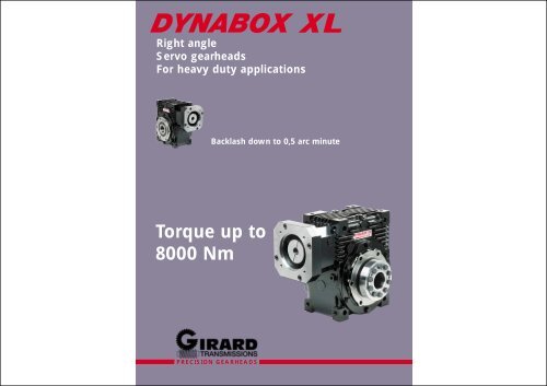
Right angle<br />
Servo gearheads<br />
For heavy duty applications<br />
Backlash down <strong>to</strong> 0,5 arc minute<br />
Torque up <strong>to</strong><br />
8000 Nm<br />
PRECISION GEARHEADS
GIRARD TRANSMISSIONS introduces :<br />
with 2 precision levels :<br />
5❏<br />
6❏<br />
1❏<br />
EXPERT : backlash < 0,5 arcminute<br />
(adjustable)<br />
MEDIUM : backlash < 5 arcminutes<br />
(fixed)<br />
❏ 1<br />
❏ 2<br />
❏ 3<br />
❏ 4<br />
❏ 5<br />
❏ 6<br />
❏ 7<br />
Computer optimized gear contact pattern : less stress, longer life.<br />
❏4<br />
3❏<br />
Keyless connection : reliable and backlash free connection with shrink disc.<br />
Universal servo-kit : including high <strong>to</strong>rsional stiffness coupling + flange.<br />
2❏<br />
Oversized taper roller bearings : provide very high permissible loads.<br />
Constant input bearings preload design : 2 taper roller bearings + 1 floating ball<br />
bearings allowing temperature variations with same preload : higher input permissible<br />
speeds, longer life.<br />
7❏<br />
Centrifugally cast wheel ring : superior shock and wear resistance.<br />
Cast iron housing<br />
2 MOUNTING OPTIONS<br />
benefits<br />
Low backlash<br />
Space saving configuration : the right-angle design, more compact,<br />
is favourable in most cases.<br />
Wormgear : very silent, more important permissible overloads, higher<br />
<strong>to</strong>rsional stiffness.<br />
Maintenance free : life-lubricated unit with high per<strong>for</strong>mances<br />
synthetic lubricant.<br />
Hollow shaft<br />
Single output shaft<br />
3
START/STOP SERVICE S5<br />
Calculate <strong>to</strong>rque S5 on gearbox output :<br />
Torque S5 = Tmax x F1 x F2<br />
SELECTION<br />
CONTINUOUS SERVICE S1<br />
Calculate <strong>to</strong>rque S1 on gearbox output :<br />
Torque S1 = Tmax<br />
Nmax 6000<br />
i<br />
Torque<br />
S5<br />
TECHNICAL SPECIFICATIONS<br />
Torque<br />
S1<br />
4000 3000 <strong>200</strong>0 1000<br />
Torque<br />
S5<br />
Torque<br />
S1<br />
Torque<br />
S5<br />
Torque<br />
S1<br />
5,<strong>125</strong>:1 792 97 609 1005 96 716 1181 96 884 1459 95 1217 <strong>200</strong>8 94 3767 50 1 13600 1<strong>200</strong>0<br />
7,2:1 840 97 632 1043 96 742 1224 95 907 1497 95 1208 1993 93 3767 38 1 15000 15000<br />
Torque<br />
S5<br />
Torque<br />
S1<br />
Torque<br />
S5<br />
Rever.<br />
E-s<strong>to</strong>p ig Fr Fa<br />
class<br />
GEARBOX RUNNING TIME DURING 1 CYCLE<br />
10 % 30 % 50 % 60 %<br />
F1 0,7 0,85 1 1,15<br />
DYNABOX XL<br />
<strong>125</strong><br />
10,25:1 832 96 622 1026 95 725 1196 95 887 1464 94 1147 1893 92 3767 30,5 1 16700 18000<br />
15,25:1 726 94 542 894 93 625 1031 92 759 <strong>125</strong>2 91 972 1604 89 3342 25 1 18900 2<strong>200</strong>0<br />
20,5:1 1026 93 759 <strong>125</strong>2 92 877 1447 91 1043 1721 89 1320 2178 87 3767 23,4 1 20600 2<strong>200</strong>0<br />
29,5:1 869 90 634 1046 88 731 1206 87 861 1421 85 1079 1780 81 3295 23,15 2 22900 2<strong>200</strong>0<br />
over 60 %, go <strong>to</strong> CONTINUOUS SERVICE selection<br />
45:1 1142 86 833 1374 84 952 1571 82 1104 1822 80 1369 2259 75 3767 21 3 26000 2<strong>200</strong>0<br />
60:1 980 82 713 1176 79 815 1345 77 929 1533 74 1150 1898 69 2937 20 3 28000 2<strong>200</strong>0<br />
NUMBER OF CYCLES/HOUR<br />
90:1 825 74 598 987 71 680 1122 68 779 1285 64 960 1584 58 2502 19 3 3<strong>200</strong>0 2<strong>200</strong>0<br />
1000 <strong>200</strong>0 3000 5000 10000<br />
F2 1 1,35 1,45 1,6 1,9<br />
5,<strong>125</strong>:1 1450 97 1128 1861 97 1324 2185 96 1648 2719 96 2334 3851 94 7251 120 1 17800 15000<br />
7,2:1 1411 97 1092 1802 96 1266 2089 96 1569 2589 95 2151 3549 94 7251 77 1 19700 19000<br />
10,25:1 1513 96 1161 1916 96 1346 2221 95 1650 2723 94 2215 3655 93 7251 63 1 21900 24000<br />
Pre-select the gearbox size :<br />
in the column Torque S5, at Nmax input speed<br />
Calculate the power Pth lost during cycle :<br />
output speed<br />
(RPM)<br />
n1,2,3 : average output speed of each period<br />
T1,2,3 : output <strong>to</strong>rque of each period<br />
n1<br />
Pre-select the gearbox size :<br />
in the column Torque S1, at Nmax input speed<br />
n2<br />
t1 t2 t3<br />
n3<br />
etc<br />
time<br />
DYNABOX XL<br />
160<br />
15,25:1 1333 95 1030 1700 94 1177 1942 93 1443 2381 92 1896 3128 90 5572 52,7 1 24700 29000<br />
20,5:1 1775 94 1338 2208 93 1530 2525 92 1856 3062 90 2392 3947 88 7251 51,5 1 27000 34000<br />
29,5:1 1492 91 1111 1833 89 1264 2086 88 1535 2533 86 1945 3209 83 6571 52,8 2 30000 34000<br />
45:1 2219 87 1630 2690 85 1858 3066 84 2211 3648 81 2765 4562 77 7251 46,5 3 34100 34000<br />
60:1 1740 83 1272 2099 81 1439 2374 79 1723 2843 76 2127 3510 71 6331 40 3 37<strong>200</strong> 34000<br />
90:1 1552 76 1123 1853 73 1261 2081 70 1489 2457 67 1842 3039 60 4933 38 3 4<strong>200</strong>0 34000<br />
5,<strong>125</strong>:1 2592 98 <strong>200</strong>8 3313 97 2392 3947 97 2954 4874 96 4208 6943 95 12826 287 1 37000 37500<br />
7,2:1 2721 97 2108 3478 97 2462 4062 96 3042 5019 96 4236 6989 94 12826 177 1 41000 44500<br />
1,2,3 : average efficiency of each period<br />
(<strong>to</strong> be calculated from page 5)<br />
t1,2,3 : duration of each period output <strong>to</strong>rque<br />
(Nm)<br />
T1<br />
T2<br />
etc<br />
time<br />
DYNABOX XL<br />
<strong>200</strong><br />
10,25:1 2691 97 2071 3417 96 2408 3973 96 2946 4861 95 4007 6612 93 12826 143 1 46000 52600<br />
15,25:1 2346 95 1813 2991 94 2083 3437 94 2540 4191 93 3376 5570 91 12448 102 1 51800 63000<br />
20,5:1 3356 94 2551 4209 93 2909 4800 92 3538 5838 91 4590 7574 89 12826 96 1 56600 71000<br />
29,5:1 2841 92 2117 3493 90 2410 3977 89 2925 4826 87 3738 6168 84 12277 99 2 63000 71000<br />
4<br />
Pth = 0,105 x<br />
3<br />
t1<br />
100 - 3<br />
1<br />
100 - 2<br />
x n1T1<br />
( ) + t2<br />
1<br />
2<br />
x n2T2<br />
( ) + t3<br />
DYNABOX XL <strong>125</strong><br />
DYNABOX XL 160<br />
DYNABOX XL <strong>200</strong><br />
LEGEND<br />
t1 + t2 + t3 + ...<br />
3 100 - 3<br />
1652W<br />
2479W<br />
4210W<br />
3<br />
x n3T3<br />
( ) + ...<br />
3<br />
Pth must be lower than the thermal capacity of the pre-selected gearbox size, otherwise select a larger gearbox.<br />
Thermal capacities :<br />
Tmax (Nm) : maximum output <strong>to</strong>rque during operating cycle / continuous operation.<br />
Nmax (RPM) : maximum input speed achieved during operating cycle.<br />
E-s<strong>to</strong>p (Nm) : gearbox output emergency <strong>to</strong>rque (2 seconds maximum duration, maximum of 25000 times).<br />
i : exact gear ratio.<br />
ig (kgxcm 2 ) : polar moment of inertia on input, without coupling (see coupling inertia page 10).<br />
(%) : gearbox efficiency.<br />
Fr (N) : maximum radial load appliable at the middle of the output shaft, without any axial load.<br />
Fa (N) : maximum axial load appliable on output shaft, without any radial load.<br />
T3<br />
45:1 3747 88 2775 4579 86 3154 5204 85 3788 6250 83 4747 7833 78 12826 82,5 3 71700 71000<br />
60:1 3170 85 2325 3836 82 2636 4349 80 3159 5212 77 3928 6481 72 11674 71 3 78000 71000<br />
90:1 2714 78 1985 3275 75 2228 3676 72 2641 4358 69 3316 5471 62 9323 69 3 88000 71000<br />
REVERSIBILITY CLASSES<br />
Reversibility means the gearbox capability <strong>to</strong> be back-driven.<br />
When selecting an irreversible gearbox, make sure that<br />
1 Totally reversible<br />
2 Uncertainly reversible<br />
3 Irreversible<br />
NOTES CONCERNING EFFICIENCY<br />
Efficiency values may be achieved after a minimum of 24<br />
hours at full load operation (running-in-period).<br />
Efficiency values are achieved only when gearbox operates at<br />
during deceleration, load inertia does not create overloads<br />
exceeding the maximum permissible <strong>to</strong>rque.<br />
nominal <strong>to</strong>rque. For gearbox operating under nominal<br />
<strong>to</strong>rque, efficiency is lower.<br />
5
DYNABOX XL HOLLOW SHAFT<br />
DYNABOX XL <strong>125</strong> 160 <strong>200</strong><br />
A 214 284 342,5<br />
B 302 377 483<br />
C 107 142 171<br />
D 214 284 342,5<br />
E 140 150 224<br />
F 180 198 288<br />
F1 222 246 374<br />
G 360 450 576<br />
H 135 175 216<br />
I 195 240 289<br />
J 35 42 48<br />
K 45 50 55<br />
L<br />
DEPENDS ON MOTOR<br />
M 185 230 300<br />
N 160 190 250<br />
O 17 22 28<br />
P 163 204 251<br />
Q 135 175 216<br />
R 111 123 187<br />
R1 90 99 144<br />
S 6 6 8<br />
S1 M16 M20 M20<br />
T 117 129 194<br />
T2 157 177 264<br />
U 65 75 100<br />
U3 80 90 140<br />
V 145 155 230<br />
W M16 M20 M20<br />
X <strong>125</strong> 160 <strong>200</strong><br />
Y 4 5 5<br />
Z 130 140 180<br />
MOUNTING POSITIONS<br />
Note : Positions F are shown with shrink disc on back side.<br />
6<br />
7
DYNABOX XL OUTPUT SHAFT<br />
DYNABOX XL <strong>125</strong> 160 <strong>200</strong><br />
A 214 284 342,5<br />
B 302 377 483<br />
C 107 142 171<br />
D 214 284 342,5<br />
E 140 150 224<br />
F 180 198 288<br />
F1 222 246 374<br />
G 360 450 576<br />
H 135 175 216<br />
I 195 240 289<br />
J 35 42 48<br />
K 45 50 55<br />
L<br />
DEPENDS ON MOTOR<br />
M 185 230 300<br />
N 160 190 250<br />
O 17 22 28<br />
P 163 204 251<br />
Q 135 175 216<br />
r 3 3 5<br />
R 111 123 187<br />
R1 90 99 144<br />
S 6 6 8<br />
S1 M16 M20 M20<br />
T 233 269 359<br />
T2 111 135 164<br />
U 75 90 120<br />
U1 67,5 81 109<br />
U2 20 25 32<br />
U4 M20 M24 M24<br />
W M16 M20 M20<br />
X <strong>125</strong> 160 <strong>200</strong><br />
Y 4 5 5<br />
Z 130 140 180<br />
MOUNTING POSITIONS<br />
1<br />
2<br />
3<br />
4<br />
H<br />
V<br />
F<br />
8<br />
9
CONNECTING KIT DYNABOX XL -SERVOMOTOR<br />
TORSION STIFF COUPLINGS<br />
L<br />
DYNABOX Reference A B C mini D E L Z<br />
<strong>125</strong> BM-F115/95 95 5 42 115 M8 247 190<br />
BM-F130/95 95 5 52 130 M8 257 190<br />
BM-F130/110 110 5 52 130 M8 257 190<br />
BM-F145/110 110 6,5 62 145 M8 267 190<br />
BM-F165/110 110 6,5 52 165 M10 257 190<br />
BM-F165/130 130 6,5 52 165 M10 257 190<br />
∅ D<br />
BM-F<strong>200</strong>/114,3 114,3 6,5 82 <strong>200</strong> M10 287 190<br />
BM-F215/130 130 6,5 62 215 M12 267 190<br />
BM-F215/180 180 6,5 62 215 M12 267 190<br />
Coupling reference AM N° 60 AM N° 80 AM N° 150 AM N° 300 AM N° 500<br />
servo shaft and DYNABOX XL shaft mm
HOW TO ORDER<br />
SERVO GEARSETS DYNASET XL WITH ADJUSTABLE BACKLASH<br />
Use following codification <strong>to</strong> order your DYNABOX XL.<br />
DYNABOX XL 160 EXPERT 45 C H1 F BM F 165/130 AM n° 60 32<br />
When DYNABOX XL servo gearheads cannot be used,<br />
the DYNASET XL servo gearsets, <strong>to</strong> be mounted in cus<strong>to</strong>med<br />
housing, are an interesting alternative.<br />
Their per<strong>for</strong>mance are comparable <strong>to</strong> complete reducers,<br />
assuming following recommendations :<br />
MOUNTING<br />
Options<br />
AM Servo coupling (page 10)<br />
BM Servo flange (pages 10 and 11)<br />
F Shrink disc <strong>for</strong> hollow shaft<br />
Wormshaft : housing and bearing design should allow<br />
an axial shifting, necessary <strong>for</strong> backlash adjustment. The<br />
<strong>to</strong>tal adjustment range is obtained with a permissible displacement<br />
equal <strong>to</strong> W, as per page 14.<br />
It is recommended, whenever possible, <strong>to</strong> use our backlash<br />
adjustment device, which is delivered preset (see page 15).<br />
The front ball bearing (see page 15) must be engaged<br />
on the shaft after the complete gear assembly,<br />
and be<strong>for</strong>e the backlash adjustment operation.<br />
Wheel ring : Arrows shown on wormshaft and<br />
wheel ring must be lined up during assembly (see<br />
page 14). As the bore A <strong>to</strong>lerance is H6, it is recommended<br />
<strong>to</strong> grind the shaft with a <strong>to</strong>lerance k5. This will eliminate<br />
any runnout between the wheel ring and the shaft.<br />
In order <strong>to</strong> facilitate the connection between the 2 parts,<br />
heat the wheel ring up <strong>to</strong> 50°C.<br />
After cooling, check that the wheel ring is no buckled, by<br />
applying a dial indica<strong>to</strong>r on its face, while rotating the<br />
shaft.<br />
It is recommended <strong>to</strong> use tapper roller bearings on output<br />
shaft, in order <strong>to</strong> allow an axial displacement of the<br />
wheel, during the mounting operations, <strong>to</strong> center the gear<br />
correctly. The contact pattern can be checked with<br />
Prussian blue or any similar product. A good pattern<br />
should be located slightly on the right side of the wheel<br />
<strong>to</strong>oth flanks (on both sides). It is normal <strong>to</strong> have no<br />
contact on the left side of the flanks. This gap is necessary<br />
<strong>for</strong> a good oil film <strong>for</strong>ming. See sketch below.<br />
Mounting positions (see pages 7 and 9)<br />
DIRECTION OF ROTATION<br />
Output option<br />
C Hollow shaft <strong>for</strong> shrink disc (not included)<br />
P Single output shaft<br />
Center plane<br />
Correct pattern<br />
LUBRICATION<br />
Reduction ratio (see page 5)<br />
The best gear per<strong>for</strong>mances in terms of efficiency, life,<br />
temperature, will be achieved with a synthetic lubricant<br />
such as MOBIL SHC 634 or equivalent. The ratings shown<br />
on page 5 can be considered only if this kind of lubricant<br />
is used.<br />
Output <strong>to</strong>rsional backlash<br />
EXPERT 0,5 arcminute<br />
MEDIUM 5 arcminutes<br />
BACKLASH ADJUSTMENT<br />
Size<br />
<strong>125</strong> 160 <strong>200</strong><br />
The accuracy of our servo gearsets DYNASET XL allows<br />
them <strong>to</strong> be set <strong>to</strong> less than 0,5 arcminute of backlash,<br />
without any efficiency or <strong>to</strong>rque capacity losses (it is assumed<br />
than cus<strong>to</strong>m machined parts and mounting are correct).<br />
If our backlash adjustment device is used, simply remove<br />
some shims (delivered) between the bearing bush and<br />
the housing, until the desired backlash value is obtained.<br />
For high speed applications, a backlash between 0,5 <strong>to</strong><br />
1 arcminute is recommended.<br />
For very intermittent applications (rotary tables or milling<br />
heads of CNC machines <strong>for</strong> ex.), a backlash down <strong>to</strong> zero<br />
is <strong>to</strong>lerated, as soon as the no load input <strong>to</strong>rque does not<br />
vary more than ± 30 % around the average value.<br />
12<br />
13
SERVO GEARSET DYNASET XL<br />
BACKLASH ADJUSTMENT DEVICE FOR DYNASET XL<br />
L<br />
C D F K<br />
G<br />
- 0<br />
- 2<br />
H<br />
I<br />
Z<br />
∅ O<br />
∅ P<br />
∅ Q<br />
U1<br />
R<br />
P<br />
Q<br />
Y<br />
BACKLASH REDUCTION DIRECTION<br />
Z<br />
∅ M<br />
∅ N<br />
∅ R<br />
∅ U<br />
∅ V<br />
∅ J<br />
Line up arrows when assembling<br />
+ 0,05/+ 0,1<br />
X<br />
∅D<br />
Axe roue<br />
X front bearing (supplied)<br />
W<br />
∅ A<br />
∅ B<br />
O ring (supplied)<br />
Adjustment shims (supplied)<br />
4 Allen screws (not supplied) S equally spaced on ∅ T<br />
(xY) ∅ S on ∅ T<br />
Surfaces marked can be referred <strong>to</strong> <strong>for</strong> checking runnout<br />
DYNASET XL<br />
<strong>125</strong> 160 <strong>200</strong><br />
A (H6) 136 190 226<br />
B Maxi 219 280 351<br />
C 63 75 91<br />
D 175 230 302,5<br />
E 40 46 58<br />
F 60,75 81 86,5<br />
G 85,75 121 155<br />
H Maxi 82 103,4 115<br />
I Maxi 33,5 43,85 46,78<br />
J (h6) 35 42 48<br />
K 45 50 55<br />
L 12 15 18<br />
M M35 x 1,5 M45 x 1,5 M60 x 1,5<br />
N (k6) 35 45 60<br />
O 44 55 72<br />
P Maxi 53 72 84<br />
Q 56,5 68 71<br />
R (k6) 50 60 60<br />
S 10,5 12,5 12,5<br />
T 154 214 260<br />
U 47 57 57<br />
U1 2,15 2,15 2,15<br />
V (c7) 50 60 60<br />
W 10 10 10<br />
X <strong>125</strong> 160 <strong>200</strong><br />
Y 10 12 12<br />
Z 20 22 35<br />
E<br />
0,1<br />
DYNASET XL<br />
<strong>125</strong> 160 <strong>200</strong><br />
D 90 110 150<br />
Y Maxi 111,4 150,9 191,1<br />
Y Mini 101,4 140,9 181,1<br />
P Maxi 163 204 251<br />
P Mini 153 194 241<br />
Q 135 175 216<br />
R 18 19 25<br />
S M12 M12 M16<br />
T 115 135 180<br />
Z 130 140 180<br />
X 6210 6212 6412<br />
The backlash adjustment device is delivered mounted and preset.<br />
Bearings are fac<strong>to</strong>ry preloaded.<br />
Backlash adjustment is operated with shims located between the housing and the bearing<br />
bush.<br />
Use following codification <strong>to</strong> order your DYNASET XL.<br />
DYNASET XL 160 90 ADJ<br />
HOW TO ORDER<br />
Option<br />
Size<br />
Backlash adj. device (see page 15)<br />
Reduction ratio (see page 5)<br />
<strong>125</strong> 160 <strong>200</strong><br />
14<br />
15
PRECISION GEARHEADS<br />
B.P. 208 - Zone Induspal - LONS 64142 BILLÈRE CEDEX FRANCE - Tél. 33 5 59 40 03 03 - Fax 33 5 59 32 11 45<br />
Visit our website : www.girard-transmissions.com <strong>to</strong> :<br />
Contact our international sales network<br />
Discover our range (<strong>to</strong>rque up <strong>to</strong> 1300 Nm)