EM-165 POSITIONING DRIVER 12-32Vdc
EM-165 POSITIONING DRIVER 12-32Vdc
EM-165 POSITIONING DRIVER 12-32Vdc

You also want an ePaper? Increase the reach of your titles
YUMPU automatically turns print PDFs into web optimized ePapers that Google loves.
<strong>EM</strong>-<strong>165</strong> <strong>POSITIONING</strong> <strong>DRIVER</strong> <strong>12</strong>-<strong>32Vdc</strong><br />
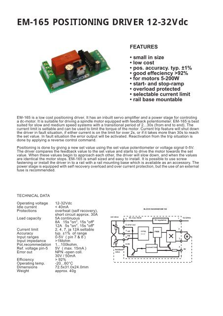
FEATURES<br />
• small in size<br />
• low cost<br />
• pos. accuracy. typ. ±1%<br />
• good effeciency >92%<br />
• for motors 5-200W<br />
• start- and stop-ramp<br />
• overload protected<br />
• selectable current limit<br />
• rail base mountable<br />
<strong>EM</strong>-<strong>165</strong> is a low cost positioning driver. It has an inbuilt servo amplifier and a power stage for controling<br />
a dc-motor. It is suitable for driving a spindle motor equipped with feedback potentiometer. <strong>EM</strong>-<strong>165</strong> is best<br />
suited for slow and medium speed systems with a transitional period of 2...30s (from end to end). The<br />
current limit is settable and can be used to limit the torque of the motor. Current trip feature will shut down<br />
the driver in fault situation, if either current is on the limit for over 2s, or if it takes more than 30s to reach<br />
the set value. In fault situation the error output will be activated. Reactivation from the trip situation is<br />
done by applying a reverse control command.<br />
Positioning is done by giving a new set value using the set value potentiometer or voltage signal 0-5V.<br />
The driver compares the feedback value to the set value and starts to drive the motor towards the set<br />
value. When these values begin to approach each other, the driver will slow down, and when the values<br />
are identical the motor stops. <strong>EM</strong>-<strong>165</strong> is small sized and easy to install. It is possible to use screw<br />
fastening or install the driver in to a rail with a rail mounting base which is available as an accessory. The<br />
power stage is equipped with self recovery overload and over current protection, but the use of an external<br />
fuse is recommended.<br />
TECHNICAL DATA<br />
Operating voltage<br />
Idle current<br />
Protections<br />
Load capacity<br />
Current limit<br />
Accuracy<br />
Input ranges<br />
Input impedance<br />
Pot.recommedation<br />
Ref. voltage pin-5<br />
Error out<br />
Efficiency<br />
Operating temp.<br />
Dimensions<br />
Weight<br />
<strong>12</strong>-<strong>32Vdc</strong><br />
< 40mA<br />
overheat (self recovery),<br />
short circuit approx. 30A<br />
5A continuous<br />
8A 15s "on", 15s "off"<br />
<strong>12</strong>A 5s "on", 15s "off"<br />
2, 4, 7, ja <strong>12</strong>A settable<br />
typ. ±1% of range<br />
0-5V ( pin 7 & 8 )<br />
>1Mohm<br />
1...100kohm.<br />
5V ( max. 15mA )<br />
NPN -open coll.<br />
30V / 50mA<br />
> 92%<br />
-20...60°C<br />
72.5x31.0x24.0mm<br />
approx. 40g<br />
set value<br />
feedback<br />
value<br />
BLOCK DIAGRAM <strong>EM</strong>-<strong>165</strong><br />
5<br />
5V, max.15mA<br />
5V regulation<br />
6 error out<br />
7 set<br />
comp. PWM<br />
< = ><br />
FB<br />
8<br />
9 0V<br />
current limit<br />
1 <strong>12</strong>-<strong>32Vdc</strong><br />
2<br />
3<br />
4<br />
0V<br />
M
OPERATING INSTRUCTIONS <strong>EM</strong>-<strong>165</strong><br />
IMPORTANT !<br />
Supply voltage must be filtered <strong>12</strong>-32 VDC with less than 20%<br />
ripple.<br />
Choose the fuse according to the application ( max. 15A ).<br />
Check the polarity before connecting.<br />
9<br />
26mm<br />
5 6 7 8<br />
2.5mm<br />
2.5mm<br />
SETTING MAP<br />
2A - without I-trip<br />
SETTINGS<br />
CURRENT TRIP ( DRIVE SHUT DOWN )<br />
The current trip function is activated with jumper named<br />
"I-trip". If current trip is activated the driver will be shut down<br />
and the error output will appear in the following cases:<br />
- overcurrent situation for over 2s<br />
- positioning takes longer than 30s.<br />
If the current trip is not activated, the driver will not be shut<br />
down, but the error output will operate in the same manner<br />
as in activated mode.<br />
CURRENT LIMIT ( MOTOR TORGUE LIMIT )<br />
There are four settable current limit values. Attached the map<br />
of the values and settings.<br />
I-limit settings<br />
I-trip activation<br />
10.5mm<br />
1 2 3 4<br />
31mm<br />
56.5mm<br />
72.5mm<br />
4A - without I-trip<br />
7A - without I-trip<br />
<strong>12</strong>A - without I-trip<br />
2A with I-trip<br />
4A with I-trip<br />
7A with I-trip<br />
<strong>12</strong>A with I-trip<br />
TAKING ON DUTY<br />
Connect the wiring and make sure, that the current limit is set<br />
according to the application (not too high!). Switch the power<br />
on. The system should now find right position and follow the<br />
adjustment of the set value potentiometer.<br />
If system only moves from end to end, or jam to the other<br />
end. Try to switch the motor wires ( pin 2 & 3 ). Check also<br />
all other wiring.<br />
If system is working o.k. but working direction is wrong. Switch<br />
both, motor wires ( pin 2 & 3 ) and the feedback potentiometer<br />
wires ( pin 5 & 9 ) at the same time.<br />
CONNECTION TERMINALS<br />
1. Supply <strong>12</strong>-<strong>32Vdc</strong><br />
2. Motor<br />
3. Motor<br />
4 Supply 0V, gnd<br />
5. 5V-out, exitation for pots. max. 15mA<br />
6. error-out NPN OPEN-COLL. max. 50mA<br />
7. Set value input, 0-5V or potentiometer<br />
8. Feedback input 0-5V or potentiometer<br />
9. 0V, signal gnd<br />
If is needed to adjust the system range, it is possible to add<br />
serial trims or resistors to the potentiometer wiring.<br />
APPLICATION 1<br />
Driver working with spindle motor equipped with<br />
potentiometer. Adjust trims can be added for range<br />
trimming, if needed.<br />
APPLICATION 2<br />
Device drives angularly adjustable table.<br />
Feedback is coming from 0-5V inclinometer.<br />
Set value is 0-5V voltage signal.<br />
set value pot.<br />
set value 0-5V<br />
"fault" indication<br />
9<br />
8 7 6 5<br />
9<br />
8 7 6 5<br />
green<br />
yellow<br />
black<br />
feedback pot.<br />
<strong>EM</strong>-<strong>165</strong><br />
1 2 3 4<br />
red<br />
blue<br />
M<br />
0V<br />
<strong>12</strong>-<strong>32Vdc</strong><br />
5V<br />
signal<br />
inclinometer<br />
0V<br />
<strong>EM</strong>-<strong>165</strong><br />
1 2 3 4<br />
DC<br />
motor<br />
0V<br />
+<strong>12</strong>-<strong>32Vdc</strong><br />
Spindle motor equipped with potentiometer, LINAK LA<strong>12</strong><br />
Inclinometer Bosch 0280 <strong>12</strong>2 201 + gearmotor<br />
ELECTROMEN Oy Vähäheikkiläntie 56B, 20810 Turku, FINLAND Tel. +358-2-4693050 Fax. +358-2-4693052