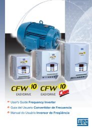
Instruction Sheet - Delta Electronics
Instruction Sheet - Delta Electronics
Instruction Sheet - Delta Electronics

You also want an ePaper? Increase the reach of your titles
YUMPU automatically turns print PDFs into web optimized ePapers that Google loves.
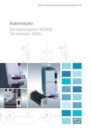
http://www.delta.com.tw/industrialautomation/<br />
Warning<br />
<strong>Instruction</strong> <strong>Sheet</strong><br />
2006-10-12<br />
5011650500-SVE0<br />
PLC that is micro, multi-functional,<br />
and with various instructions<br />
This instruction sheet only provides introductory information on electrical specification, functions, wiring,<br />
trouble-shooting and peripherals. For more information, please refer to “DVP-PLC Application Manual:<br />
Programming”. For how to purchase its peripheral devices, please refers to the manual enclosed with the<br />
product or “DVP-PLC Application Manual”.<br />
DVP28SV is an OPEN-TYPE device and therefore should be installed in an enclosure free of airborne<br />
dust, humidity, electric shock and vibration. The enclosure should prevent non-maintenance staff from<br />
operating the device (e.g. key or specific tools are required for opening the enclosure) in case danger and<br />
damage on the device may occur.<br />
DO NOT connect input AC power supply to any of the I/Ot terminals; otherwise serious damage may<br />
occur. Check all the wiring again before switching on the power and Do NOT tough any terminal when<br />
the power is switched on. Make sure the groud terminal is correctly grounded in order to prevent<br />
electromagnetic interference.<br />
Introduction<br />
1.1 Model Explanation and Peripherals<br />
Thank you for choosing <strong>Delta</strong> DVP28SV. 28SV is a 28-point (16 input + 12 output) PLC MPU, offering various<br />
instructions and is with 16K Steps program memory, able to connect with all SS/SA/SX/SC/SV series extension<br />
models, including digital input/output (max. 512 input/output extension points), analog modules (A/D, D/A<br />
tranformation and termperature units) and all kinds of new high-speed extenstion modules. Its 4-group high-speed<br />
(200KHz) pulse outputs and the two new 2-axis interpolation instructions satisfy all kinds of applications.<br />
DVP28SV is small in size and easy to install.<br />
Nameplate Explanation<br />
Model Name Explanation<br />
Series name<br />
Points (16inputs+12outputs)<br />
SV series<br />
<strong>Delta</strong> PLC model name<br />
Power input specification<br />
Output module specification<br />
Barcode & serial No.<br />
Version<br />
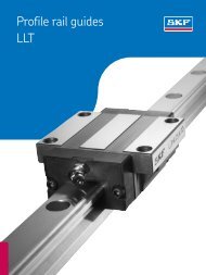
1.2 Product Profile and Outline<br />
60<br />
11<br />
12<br />
19<br />
13<br />
14<br />
1<br />
20 2<br />
3<br />
4<br />
5<br />
6<br />
7<br />
10<br />
Unit: mm<br />
21<br />
70<br />
R: Relay<br />
T: Transistor<br />
DC power input<br />
15<br />
16<br />
VX.XXXX<br />
3<br />
8<br />
90<br />
9<br />
17<br />
18<br />
3<br />
24Vdc 6W<br />
2.0A 250Vac 50/60Hz RES LOAD<br />
28SV11R0T6020001<br />
M A D E I N X X X X X<br />
Serial No. Explanation<br />
Production No.<br />
Production week<br />
Production year (2006)<br />
Production plant (Taoyuan)<br />
Version No.<br />
Model name<br />
1 POWER/RUN/BAT.LOW/ERROR indicator<br />
2 COM1(RS-232) receiving communication (Rx) indicator<br />
3 COM2(RS-485) sending communication (Tx) indicator<br />
4 Input/output indicator<br />
5 RUN/STOP switch<br />
6 VR0: M1178 enabled/D1178 corresponding value<br />
7 VR1: M1179enabled/D1179 corresponding value<br />
8 Input/output terminal<br />
9 COM1(RS-232) program I/O communication port<br />
10 DIN rail clip<br />
11 Extension module positioning hole<br />
12 Extension module connection port<br />
13 DIN rail (35mm)<br />
14 Extension module fastening clip<br />
15 COM2(RS-485) communication port (Master/Slave)<br />
16 Power input port<br />
17 3 P removable terminal (standard component)<br />
18 Power input connection cable (standard component)<br />
19 New high-speed extension module connection port<br />
20 Nameplate<br />
21 Direct fastening hole<br />
Function Specifications<br />
Item Specification Note<br />
Operation control method Stored program; cyclic scanning system<br />
I/O control method<br />
Batch processing and refresh I/O status when END With instruction that can<br />
instruction is executed<br />
immediately refresh I/O status<br />
Operation processing speed Basic instruction (min. 0.24 us) Application instruction<br />
Program language <strong>Instruction</strong> + ladder diagram + SFC With step instruction<br />
Program capacity<br />
15,872 STEPS<br />
SRAM + rechargeable battery +<br />
Flash<br />
<strong>Instruction</strong> type<br />
32 basic sequential instructions (including step ladder<br />
instructions)<br />
193 application instructions<br />
X External input relay X0 ~ X377, octal encoding; 256 points<br />
Total 512<br />
Corresponds to external input<br />
points<br />
Y External output relay Y0 ~ Y377, octal encoding; 256 points<br />
points Corresponds to external output<br />
points<br />
General purpose M0 ~ M499, 500 points (*2)<br />
M500 ~ M999, 500 points (*3)<br />
Auxiliary Latched<br />
Total 4,096 The contact can be On/Off in the<br />
M<br />
relay<br />
M2000 ~ M4095, 2,096 points (*3)<br />
points program.<br />
M1000 ~ M1999, 1,000 points (part for<br />
Special purpose<br />
latched)<br />
T0 ~ T199, 200 points (*2)<br />
100 ms<br />
T192 ~ T199 for subroutine<br />
Timer indicated by TMR<br />
T250 ~ T255, 6 accumulative points (*4) Total 256 instruction. If timing reaches its<br />
T Timer<br />
T200 ~ T239, 40 points (*2)<br />
points target, the T contact of the same<br />
10 ms<br />
T240 ~ T245, 6 accumulative points (*4)<br />
No. will be On.<br />
1 ms T246 ~ T249, 4 accumulative points (*4)<br />
16-bit<br />
C0 ~ C99, 100 points (*2)<br />
counting up C100 ~ C199, 100 points (*3)<br />
32-bit counting C200 ~ C219, 20 points (*2)<br />
Counter indicated by CNT (DCNT)<br />
up/down Total 253 instruction. If counting reaches its<br />
C Counter<br />
C220 ~ C234, 15 points (*3)<br />
points target, the C contact of the same<br />
C235 ~ C244, 1 phase 1 input, 10 points (*3)<br />
32-bit high-speed<br />
No. will be On.<br />
counting up/down<br />
C246 ~ C249, 1 phase 2 inputs, 4 points (*3)<br />
C251 ~ C254, 2 phase 2 inputs, 4 points (*3)<br />
Initial S0 ~ S9, 10 points (*2)<br />
For zero return<br />
S10 ~ S19, 10 points, used with IST<br />
instruction (*2)<br />
Relay (bit)<br />
Register (word data)<br />
Index<br />
Constant<br />
S<br />
Step<br />
points<br />
General purpose S20 ~ S499, 480 points (*2)<br />
Latched S500 ~ S899, 400 points (*3)<br />
For alarm S900 ~ S1023, 124 points (*3)<br />
Total 1,024<br />
points<br />
Used for SFC<br />
Latched area setup<br />
Start: D1214(K500)<br />
End: D1215(K899)<br />
T Present value in timer T0 ~ T255, 256 points<br />
When timing reaches the target,<br />
the contact continuity of timer<br />
appears.<br />
C0 ~ C199, 16-bit counter, 200 points<br />
When counting reaches the target,<br />
C Present value in counter<br />
the contact continuity of counter<br />
C200 ~ C254, 32-bit counter, 53 points<br />
appears.<br />
General purpose D0 ~ D199, 200 points (*2)<br />
D<br />
D200 ~ D999, 800 points (*3)<br />
Latched<br />
Total Memory area for data storage; can<br />
Data<br />
D2000 ~ D9999, 8,000 points (*3)<br />
10,000 be used for special indirect<br />
register Special purpose D1000 ~ D1999, 1,000 points<br />
points indication.<br />
For Indirect<br />
indication<br />
E0 ~ E7, F0 ~ F7, 16 points (*1)<br />
N/A File register 0 ~ 9,999 (10,000 points) (*4) Extension register for data storage<br />
N For main control loop N0 ~ N7, 8 points Control point for main control loop<br />
P For CJ, CALL instructions P0 ~ P255, 256 points Position index of CJ and CALL<br />
I<br />
K<br />
Interruption subroutine<br />
Decimal<br />
External interruption<br />
Time interruption<br />
Interruption when<br />
high-speed counting<br />
reaches its target<br />
Interruption during<br />
pulse output<br />
Interruption during<br />
communication<br />
I00□(X0), I10□(X1), I20□(X2), I30□(X3), I40□(X4), I50<br />
□(X5), 6 points (□=1: rising-edge trigger; □=0:<br />
falling-edge trigger)<br />
I6□□(1ms), I7□□(1ms), I8□□(0.1ms) (□□=1~99)<br />
I010, I020, I030, I040, I050, I060, 6 points<br />
I110, I120, I130, I140, 4 points<br />
I150, I160, I170, 3 points<br />
K-32,768 ~ K32,767 (16-bit operation)<br />
K-2,147,483,648 ~ K2,147,483,647(32-bit operation)<br />
Position index for interruption<br />
subroutine<br />
H Hex H0000 ~ HFFFF (16-bit operation), H00000000 ~ HFFFFFFFF (32-bit operation)<br />
F<br />
Floating point<br />
Serial communication ports (program<br />
write in/read out)<br />
Analog rotary switch/RTC<br />
Special extension module<br />
Displaying floating points by the length of 32 bits with IEEE754 standard<br />
±1.1755 × 10 -38 ~ ±3.4028 × 10 +38<br />
COM1: RS-232; COM2: RS-485 (can be master or slave);<br />
COM1 and COM2 can be used at the same time<br />
Built-in 2 points VR/ RTC in MPU<br />
Right-side extension module and SS series share all modules, AD, DA, PT, TC, XA, PU<br />
(max. 8 modules extendable)<br />
Left-side can be connected with new high-speed extension modules (max. 8 module<br />
extendable)<br />
*1. Non-latched area cannot be modified.* 2. The preset non-latched area can be modified into latched area by setting up parameters.* 3. The<br />
preset latched area can be modified into non-latched area by setting up parameters. *4. The fixed latched area cannot be modified<br />
After the DC24V power is switched off, the data in the latched area are stored in SRAM memory and its power is<br />
supplied by the rechargeable battery. Therefore, when the battery is damaged or cannot be changed, the data in the<br />
program and latched area will be lost. If the user needs to permanently save the data in the latched area in the<br />
program and device D, please refer to “Flash ROM permanently saved and recover mechanism” as stated below.<br />
Permanently saved mechanism:<br />
The user can use WPLSoft (Options -> PLCFlash) to indicate whether to permanently store the data in the<br />
latched area in the program (including password) and device D in Flash ROM memory (new indicated data will<br />
replace all data previously saved in the memory).<br />
Recover mechanism:<br />
If the rechargeable battery is in low voltage, resulting in the loss of data in the program, PLC will automatically<br />
restore the data in the latched area in the program and device D of Flash ROM into SRAM memory (M1176 = On)<br />
next time when DC24V is re-powered. The ERROR LED flashing will remind the user that if the recorded program is<br />
able to resume its execution, the user only needs to shut down and re-power the PLC once to restart its operation<br />
(RUN).<br />
M<br />
(Auxiliary<br />
relay)<br />
General purpose Latched Special auxiliary relay Latched<br />
M0 ~ M499 M500 ~ M999 M1000 ~ M1999 M2000 ~ M4095<br />
Preset for latched<br />
Start: D1200 (K512)<br />
End: D1201 (K999)<br />
Part for latched; cannot be<br />
modified<br />
Start: D1202 (K2,000)<br />
End: D1203 (K4,095)<br />
T<br />
(Timer)<br />
C<br />
(Counter)<br />
S<br />
(Step relay)<br />
D<br />
(Register)<br />
File<br />
register<br />
100 ms 10 ms 10 ms 1 ms 100 ms<br />
T0 ~ T199 T200 ~ T239 T240 ~ T245 T246 ~ T249 T250 ~ T255<br />
Preset for non-latched Preset for non-latched<br />
Accumulative-type<br />
Start: D1204 (K-1) *1 Start: D1206 (K-1) *1<br />
Latched fixed<br />
End: D1205 (K-1) *1 End: D1207 (K-1) *1<br />
16-bit counting up 32-bit counting up/down 32 bit high-speed counting up/down<br />
C0 ~ C99 C100 ~ C199 C200 ~ C219 C220 ~ C234 C235 ~ C245 C246 ~ C255<br />
Preset for Preset for Preset for Preset for<br />
non-latched latched non-latched latched<br />
Preset for latched<br />
Start: D1208 (K96)<br />
Start: D1210 (K216)<br />
Start: D1212 (K235)<br />
End: D1209 (K199)<br />
End: D1211 (K234)<br />
End: D1213 (K255)<br />
Initial For zero return General purpose Latched Alarm step<br />
S0 ~ S9 S10 ~ S19 S20 ~ S499 S500 ~ S899 S900 ~ S1023<br />
Preset for non-latched<br />
Preset for latched<br />
Start: D1214 (K500) / End: D1215 (K899)<br />
Latched fixed<br />
General purpose Latched Special register Latched<br />
D0 ~ D199 D200 ~ D999 D1000 ~ D1999 D2000 ~ D9999<br />
Preset for non-latched Preset for latched Preset for latched<br />
K0 ~ K9999<br />
Latched fixed<br />
Start: D1216 (K200)<br />
End: D1217 (K999)<br />
When the power is On/Off or MPU is switched between RUN/STOP mode:<br />
Memory type<br />
Non-latched<br />
Power<br />
Off On<br />
Cleared<br />
STOPRUN<br />
Unchanged<br />
RUNSTOP<br />
Cleared when<br />
M1033 = Off<br />
Unchanged when<br />
M1033 = On<br />
Part for latched; cannot<br />
be modified<br />
Clear non-latched<br />
area in M1031<br />
Start: D1218 (K2000)<br />
End: D1219 (K9999)<br />
Clear latched<br />
area in M1032<br />
Initial factory<br />
setting<br />
Cleared Unchanged 0<br />
Latched Unchanged Unchanged Cleared 0<br />
Special M, special D<br />
(Indirect indicated register)<br />
Initial<br />
setting<br />
Unchanged Unchanged Initial setting<br />
File register Unchanged 0<br />
Electrical Specifications<br />
Model<br />
Item<br />
Power supply voltage<br />
Inrush current<br />
Power consumption<br />
Insulation resistance<br />
Noise immunity<br />
Earth<br />
Operation/storage<br />
Vibration/shock immunity<br />
DVP28SV11R<br />
DVP28SV11T<br />
24VDC (-15% ~ 20%) (with counter-connection protection on the polarity of DC input power)<br />
Max. 2.2A@24VDC<br />
6W<br />
>5 MΩ (all I/O point-to-ground: 500VDC)<br />
ESD (IEC 61131-2, IEC 61000-4-2): 8KV Air Discharge<br />
EFT (IEC 61131-2, IEC 61000-4-4): Power Line: 2KV; Digital I/O: 1KV,<br />
Analog & Communication I/O: 1KV<br />
Damped-Oscillatory Wave: Power Line: 1KV, Digital I/O: 1KV<br />
RS (IEC 61131-2, IEC 61000-4-3): 26MHz ~ 1GHz, 10V/m<br />
The diameter of grounding wire shall not be less than that of the wiring terminal of the power.<br />
(When many PLCs are in use at the same time, please make sure every PLC is properly<br />
grounded.)<br />
Operation: 0ºC ~ 55ºC (temperature); 50 ~ 95% (humidity); pollution degree 2<br />
Storage: -40ºC ~ 70ºC (temperature); 5 ~ 95% (humidity)<br />
International standards: IEC1131-2, IEC 68-2-6 (TEST Fc)/IEC1131-2 & IEC 68-2-27 (TEST Ea)<br />
Weight (g) 260g 240g<br />
Input<br />
point<br />
Output<br />
point<br />
Type Current Motion level Responding time<br />
X0~X7,X12~ X10~X11,X14~<br />
DC (Sink 24VDC<br />
X0~X17<br />
Approx. 10 ms (can be<br />
X13,X16~X17 X15<br />
OnOff<br />
adjusted within the range of 10<br />
or Source) 5mA OffOn OffOn<br />
~ 60 ms by D1020 and<br />
16.5VDC >18.5VDC<br />
D1021)<br />
Type Current Voltage Max. loading<br />
Responding<br />
time<br />
relay-R<br />
transistor-<br />
T<br />
1.5A/1 point<br />
(5A/COM)<br />
General: 0.3A/1<br />
point @40ºC<br />
High-speed: <<br />
1KHz, 0.3A/1 point<br />
@ 40ºC; ≥1KHz,<br />
30mA/1point@40<br />
ºC<br />
250VAC,<br />
>30VDC<br />
30VDC<br />
Model & I/O Configuration<br />
Standard Functional MPU<br />
Model<br />
DVP28SV11R<br />
DVP28SV11T<br />
Power<br />
24VDC 16<br />
75VA<br />
(inductive)<br />
90 W<br />
(resistive)<br />
Max. 10KHz<br />
for Y5, Y7,<br />
Y10 ~ Y13<br />
Max. 200KHz<br />
for Y0, Y1,<br />
Y2, Y3, Y4,<br />
Y6<br />
Input/output specification<br />
Input<br />
Output<br />
Point Type Point Type<br />
DC (Sink<br />
Or<br />
Source<br />
12<br />
Relay<br />
Transistor<br />
Approx.<br />
10 ms<br />
OffOn 20us<br />
OnOff 30us<br />
OffOn 0.2us<br />
OnOff 0.2us<br />
S/S<br />
X0<br />
X1<br />
X2<br />
X3<br />
X4<br />
X5<br />
X6<br />
X7<br />
S/S<br />
X10<br />
X11<br />
X12<br />
X13<br />
X15<br />
X16<br />
X17<br />
Relay<br />
C0<br />
Y0<br />
Y1<br />
Y2<br />
C1<br />
Y3<br />
Y4<br />
Y5<br />
C2<br />
Y6<br />
Y7<br />
Y10<br />
C3<br />
Y11<br />
Y12<br />
Y13<br />
Mechanical<br />
life<br />
2×10 7<br />
times<br />
(without<br />
load)<br />
Electrical life<br />
1.5×10 5 times<br />
(5A 30VDC)<br />
5×10 5 times (3A<br />
120VAC)<br />
3×10 4 times (5A<br />
250VAC)<br />
- -<br />
I/O configuration<br />
Transistor<br />
S/S<br />
X0<br />
X1<br />
X2<br />
X3<br />
X4<br />
X5<br />
X6<br />
X7<br />
S/S<br />
X10<br />
X11<br />
X12<br />
X13<br />
X15<br />
X16<br />
X17<br />
C0<br />
Y0<br />
Y1<br />
C1<br />
Y2<br />
Y3<br />
C2<br />
Y4<br />
Y5<br />
C3<br />
Y6<br />
Y7<br />
C4<br />
Y10<br />
Y11<br />
Y12<br />
Y13
Installation & Wiring<br />
5.1 Mounting & Wiring<br />
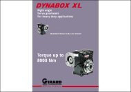
How to install DIN rail<br />
DVP-PLC can be secured to a cabinet by using the DIN rail of 35mm in height and 7.5mm in depth. When mounting<br />
PLC to DIN rail, be sure to use the end bracket to stop any side-to-side movement of PLC and reduce the chance of<br />
wires being loosen. A small retaining clip is at the bottom of PLC. To secure PLC to DIN rail, place the clip onto the<br />
rail and gently push it up. To remove it, pull the retaining clip down and gently remove PLC from DIN rail, as shown<br />
in figure 1.<br />
How to screw<br />
Please use M4 screw (see figure 2) according to the dimension of the product. Please install PLC in an enclosure<br />
with sufficient space around it to allow heat dissipation (see figure 3).<br />
Wiring<br />
< 1.5mm<br />
101<br />
109.4<br />
70<br />
53.2<br />
Figure 1 Figure 2 (Unit: mm) Figure 3<br />
22-16AWG<br />
90<br />
D<br />
D<br />
PLC<br />
D<br />
D<br />
D > 50 mm<br />
1. Use 22-16AWG (1.5mm) single or multiple core wire on I/O wiring<br />
terminals. The specification of the terminal is shown in the figure on the<br />
left. The PLC terminal screws shall be tightened to 1.95 kg-cm (1.7 in-lbs).<br />
2. DO NOT place the I/O signal wires and power supply wire in the same<br />
wiring duct.<br />
3. Use 60/75 ºC copper wires only.<br />
DO NOT install PLC in an environment with:<br />
Dust, smoke, metallic debris, corrosive or flammable gas<br />
High temperature, humidity<br />
Direct shock and vibration<br />
5.2 Notes<br />
Power input wiring<br />
The power input of DVP-SV series is DC. When operating SV series, please make sure that:<br />
1. The power is connected to the two terminals, 24VDC and 0V, and the range of power is 20.4VDC ~ 28.8VDC.<br />
If the power voltage is less than 20.4VDC, PLC will stop running, all outputs will go “Off” and ERROR<br />
indicator will flash continuously.<br />
2. The power shutdown of less than 10 ms will not affect the operation of PLC. However, power shutdown time<br />
that is too long or the drop of power voltage will stop the operation of PLC and all outputs will go “Off”. When<br />
the power supply turns normal again, PLC will automatically return to its operation. (Please be aware of the<br />
latched auxiliary relays and registers inside PLC when programming.)<br />
20.4V~28.8V<br />
2A<br />
24V<br />
0V<br />
DC power input<br />
DC/DC<br />
S/S X0 X1 X2<br />
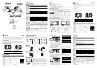
Safety wiring<br />
Since DVP28SV is only compatible with DC power supply, <strong>Delta</strong> power supply modules (DVPPS01/DVPPS02) are<br />
suitable power supplies for DVP28SV. Users are suggested to install the protection circuit at the power supply<br />
terminal to protect DVPPS01 or DVPPS02.<br />
8<br />
5<br />
L<br />
N<br />
MC<br />
4<br />
Guard<br />
Limit<br />
6<br />
3<br />
MC<br />
2<br />
MC<br />
7<br />
1<br />
1<br />
<br />
<br />
<br />
<br />
<br />
<br />
<br />
<br />
Input point wiring<br />
There are two types of DC inputs, SINK and SOURCE.<br />
5V<br />
AC power supply load<br />
Power circuit protection fuse (3A)<br />
Power indicator<br />
Emergency stop<br />
This button can cut off the system power supply when accidental<br />
emergency takes place.<br />
System circuit isolation device<br />
The device is made of electromagnetic contactor and relay as the<br />
switch to prevent the instability of system when the power is<br />
intermittently supplied.<br />
DVPPS01 / DVPPS02 (main processing unit)<br />
Earth<br />
Power supply<br />
AC: 100 ~ 240VAC, 50/60Hz<br />
DC Signal IN<br />
S/S<br />
Sinking<br />
X0<br />
SINK mode<br />
(common port for current input<br />
S/S)<br />
DC Signal IN<br />
X0<br />
S/S<br />
Sourcing<br />
SOURCE mode<br />
(common port for current<br />
output S/S)<br />
Output point wiring<br />
DVP-**-**-11-R<br />
LED<br />
DVP-**-**-11-T<br />
LED<br />
RY<br />
Y0<br />
C0<br />
LOAD<br />
RELAY OUTPUT<br />
T<br />
R<br />
G<br />
POWER<br />
LOAD<br />
Y0<br />
< 0.3A<br />
C0<br />
TRANSISTOR OUTPUT<br />
Relay (R) contact circuit wiring<br />
DVP-**-**-**-R<br />
LED<br />
RY<br />
Y0<br />
C0<br />
RELAY OUTPUT<br />
LOAD<br />
Input point loop equivalent circuit<br />
+24V<br />
24G<br />
S/S<br />
X0<br />
24VDC<br />
Input point loop equivalent circuit<br />
+24V<br />
24G<br />
S/S<br />
X0<br />
24VDC<br />
+5V<br />
+5V<br />
SINK<br />
SOURCE<br />
Wiring loop<br />
+24V 24G S/S X0 X1 X2<br />
Sink Type<br />
Wiring loop<br />
+24V 24G S/S X0 X1 X2<br />
Source Type<br />
1. DVP-SV series have two output modules, relay and transistor. See “Function<br />
Specifications” for their specifications.<br />
2. Be aware of the connection of shared terminals when wiring output terminals.<br />
3. Output terminals, Y0, Y1, and Y2, of relay models use C0 common port; Y3,<br />
Y4, and Y5 use C1 common port; Y6, Y7, and Y10 use C2 common port;<br />
Y11, Y12, and Y13 use C3 common port, as shown below.<br />
C0 Y0 Y1 Y2 C1 Y3 Y4 Y5 C2 Y6 Y7 Y10 C3 Y11Y12 Y13<br />
When output points are enabled, their corresponding indicators on the front<br />
panel will be on.<br />
4. Output terminals, Y0 and Y1, of transistor models use C0 common port; Y2<br />
and Y3 use C1 common port; Y4 and Y5 use C2 common port; Y6 and Y7<br />
use C3 common port; Y10, Y11, Y12 and Y13 use C4 common port, as<br />
shown below.<br />
C0 Y0 Y1 C1 Y2 Y3 C2 Y4 Y5 C3 Y6 Y7 C4 Y10 Y11 Y12 Y13<br />
5. Isolation circuit: The optical coupler is used to isolate signals between the<br />
circuit inside PLC and input modules.<br />
POWER<br />
6<br />
2<br />
3<br />
5<br />
C0 Y0 Y1 C1 Y3 Y4 C2 Y6 Y7<br />
Flywheel diode (SB360 3A 60V): To extend the life span of contact Emergency stop: Uses external switch<br />
Fuse: Uses 5 ~ 10A fuse at the common port of output contacts to protect the output circuit.<br />
Varistor: To reduce the interference on AC load (R=100~120Ω, C=0.1~0.2uF)<br />
DC power supply<br />
1<br />
9<br />
3<br />
2<br />
8<br />
MC1<br />
10<br />
MC2<br />
Empty terminal: not in use<br />
Neon indicator<br />
AC power supply<br />
Incandescent light (resistive load)<br />
Manually exclusive output: Uses external circuit and forms an interlock, together with the PLC internal program, to ensure<br />
safety protection in case of any unexpected errors.<br />
Transistor (T) contact circuit wiring<br />
DVP-**-**-**-T<br />
LED<br />
DC power supply<br />
Circuit protection fuse<br />
<br />
Y0<br />
C0<br />
< 0.5A<br />
TRANSISTOR OUTPUT<br />
LOAD<br />
1<br />
2<br />
5 5<br />
C0 Y0 Y1 C4 Y10 Y11 Y12 Y13<br />
4<br />
Emergency stop<br />
Flywheel diode (SB360 3A 60V) + inductive load<br />
Manually exclusive output: Uses external circuit and forms an interlock, together with the PLC internal program, to ensure<br />
safety protection in case of any unexpected errors.<br />
Trial Operation<br />
Preparation<br />
1. Before powering DVP28SV, be sure that you have checked if the I/O wiring is correct. You may damage<br />
PLC if AC110V or AC220V is directly supplied to input terminals or the output wiring is short-circuited.<br />
3<br />
3<br />
4<br />
MC1<br />
MC2<br />
7<br />
R<br />
C<br />
4<br />
2. When the peripheral devices are used to write program into PLC: If the ERROR indicator does not flash,<br />
the program you are using is legal and PLC is waiting for RUN instruction from you.<br />
3. You can use HPP or WPLSoft to test “force On/Off” of output contacts.<br />
Operation & test<br />
1. If the ERROR indicator does not flash, you can use RUN/STOP switch or peripheral device (HPP or<br />
WPLSoft) to give RUN instruction and the RUN indicator should be continuously on at this time. That the<br />
RUN indicator does not flash indicates PLC has no program in it.<br />
2. When PLC is in operation, use HPP or WPLSoft to monitor the set value or temporarily saved value in<br />
timer (T), counter (C), and register (D) and force On/Off of output contacts. That the ERROR indicator is<br />
on (not flashes) indicates that part of the program exceeds the preset time-out. In this case, you have to<br />
set the RUN/STOP switch as STOP first, check special register D1008 and obtain the location in the<br />
program where time-out takes place. We suggest you use WDT instruction to correct this problem.<br />
Operation of PLC basic sequential instructions & application instructions<br />
1. The basic sequential instructions and application instructions of DVP-SV series are compatible with all<br />
<strong>Delta</strong> DVP series PLCs. See <strong>Delta</strong> “DVP-PLC Application Manual” for relevant information.<br />
2. All <strong>Delta</strong> DVP series PLCs are compatible with DVPHPP handheld programming panel, WPLSoft ladder<br />
diagram for program editing and exclusive transmission cables to connect with DVP28SV for program<br />
transmission, MPU control, program monitoring and so on.<br />
How to identify abnormality of PLC<br />
To identify abnormality from the indicators on the panel, please check:<br />
POWER indicator<br />
When PLC is powered, the POWER LED indicator on the front panel will be on (in green). That this indicator is<br />
not on or the ERROR indicator continuously flashes when PLC is powered indicates that the power supply +24V<br />
is insufficient or DC power supply 24V is overloaded. In this case, change another DC24V power supply. If the<br />
indicator is still off at this time, your PLC is malfunctioned. Send your PLC back to your distributor for repair.<br />
RUN indicator<br />
Check your PLC status. When PLC is running, this indicator will be on. You can use HPP, the ladder diagram<br />
editing program or the switch on the panel to RUN or STOP PLC.<br />
ERROR indicator<br />
1. If you enter illegal program into PLC or use instructions or devices that exceed their range, this indicator will<br />
flash (approx. every 1 second). When this happens, you have to obtain the error code from D1004 and save<br />
the address where the error occurs in register D1137 (if the error is a general circuit error, the address of<br />
D1137 will be invalid). Find out the cause of the error, amend the program and resend the program to PLC. If<br />
you cannot connect to PLC and this indicator keeps flashing quickly (approx. every 0.2 second), there<br />
should be insufficient 24VDC power supply. Please check if the 24VCD is overloaded.<br />
2. If the ERROR indicator keeps flashing, you have to check the special relay M1008. M1008 is on indicates<br />
that the execution time of program loop exceeds the preset time-out (in D1000). In this case, turn the<br />
RUN/STOP switch to STOP, check the special register D1008 and obtain the location in the program where<br />
the time-out takes place. We suggest you use WDT instruction to correct this problem. After amending the<br />
program, you only need to resend the program to stop the indicator from flashing. If the indicator still keeps<br />
flashing at this time, switch off the power and check if there is any interference existing or conductive<br />
invader inside PLC.<br />
For details of error codes (in D1004, hex coding), see “DVP-PLC Application Manual: Programming”.<br />
BAT.LOW indicator<br />
1. The rechargeable lithium-ion battery in DVP-28SV is mainly used on the latched procedure and data<br />
storage.<br />
2. The lithium-ion battery has been fully charged in the factory and is able to retain the latched procedure and<br />
data storage for 12 months. If DVP28SV has not been powered and used for more than 12 months, the<br />
battery will be out of power upon normal consumption and the procedure and data will be lost.<br />
3. The lithium-ion battery has longer life span than ordinary battery; therefore there is no need to change<br />
battery very frequently. You can charge the battery at any time without having to worry its chargeability will<br />
decrease. You can also recharge the battery even when there is still power in the battery.<br />
4. Please be aware of the date of manufacturing; the charged battery can sustain for 12 months from this date.<br />
If you find out the BAT.LOW indicator stays on after PLC is powered, the battery voltage is low and the<br />
battery is being charged. DVP28SV has to remain on for more than 24 hours to fully charge the battery. If<br />
the indicator turns from on to “flash” (every 1 second), it indicates that the battery cannot be charged<br />
anymore. Please correctly process your data in time and send the PLC back to <strong>Delta</strong> for changing a new<br />
battery.<br />
Input indicator<br />
On/Off of input point is indicated by input indicator or monitored by HPP. When the action criteria of the input<br />
point are true, this indicator will be on. If abnormality is identified, check if the indicator and input circuit are<br />
normal. Use of electronic switch with too much electricity leakage often results in unexpected actions of the input<br />
point.<br />
Output indicator<br />
On/Off of output point is indicated by output indicator. When the output indicator (On/Off) does not correspond to<br />
the action of its load, please be aware of the follows:<br />
1. The output contact may be melted or blocked out of overloading or short-circuited load, which will result in<br />
poor contact.<br />
2. If you are suspicious that the output point may execute undesired action, check the output wiring circuit and<br />
whether the screw is properly tightened.<br />
Accuracy (second/month) of RTC<br />
Temperature (°C/°F) 0 / 32 25 / 77 55 / 131<br />
Max. inaccuracy (second/month) -117 52 -132<br />
The content of this instruction sheet may be revised without prior notice. Please consult our distributors or<br />
download the most updated version at http://www.delta.com.tw/industrialautomation