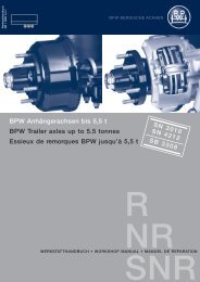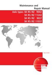
Conversion Hub Unit SK RB/RLB to Hub Unit SK ... - Jupojos technika
Conversion Hub Unit SK RB/RLB to Hub Unit SK ... - Jupojos technika
Conversion Hub Unit SK RB/RLB to Hub Unit SK ... - Jupojos technika

Create successful ePaper yourself
Turn your PDF publications into a flip-book with our unique Google optimized e-Paper software.
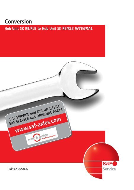
<strong>Conversion</strong><br />
<strong>Hub</strong> <strong>Unit</strong> <strong>SK</strong> <strong>RB</strong>/<strong>RLB</strong> <strong>to</strong> <strong>Hub</strong> <strong>Unit</strong> <strong>SK</strong> <strong>RB</strong>/<strong>RLB</strong> INTEGRAL<br />
SAF SERVICE und ORIGINALTEILE<br />
SAF SERVICE and ORIGINAL PARTS<br />
www.saf-axles.com<br />
Edition 06/2006<br />
Service
Vehicle and axle identification<br />
Trailer Manufacturer...........................................................................................................................<br />
Body type............................................................................................................................................<br />
Chassis no............................................................................................................................................<br />
Year of manufacture/Trailer date in Service....................................................................................<br />
For the warranty procedure<br />
quote correct Axle Identificationand<br />
Serial-No.<br />
Type plate for axle identification<br />
Ident-No. Prod.-No. (Serial-No.)<br />
Example: 14732487480 014033241<br />
1. Axle<br />
2. Axle<br />
3. Axle<br />
11396GB Edition 0606<br />
169.02.3417<br />
Identification of axles in case of type plate absence<br />
Serial No. on spindle end, Rh side.<br />
4. Axle<br />
5. Axle<br />
Enter axle data from SAF type plate<br />
2
Contents<br />
GB<br />
Page<br />
Identification of SAF axles ......................................................................................................................................2<br />
General safety instructions ....................................................................................................................................5<br />
Service instructions ..................................................................................................................................................6<br />
<strong>Hub</strong> <strong>Unit</strong> conversion kit ..........................................................................................................................................7<br />
Illustration of the axle <strong>SK</strong> <strong>RB</strong> / <strong>RLB</strong> 9019 / 9022 ..................................................................................................8<br />
Installation instructions<br />
Remove brake pads ..........................................................................................................................................9<br />
Remove brake callipers ....................................................................................................................................9<br />
Remove <strong>Hub</strong> <strong>Unit</strong> <strong>SK</strong> <strong>RB</strong> / <strong>RLB</strong> with wheel flange and brake disc ..........................................................9-10<br />
Prepare stub axle............................................................................................................................................10<br />
Install <strong>Hub</strong> <strong>Unit</strong> <strong>SK</strong> <strong>RB</strong> / <strong>RLB</strong> INTEGRAL with brake disc on stub axle ..................................................11-12<br />
Install brake calliper on brake backing plate..........................................................................................12-14<br />
Install brake pads............................................................................................................................................14<br />
Install brake cylinder on brake calliper ........................................................................................................14<br />
Adjust clearance ............................................................................................................................................15<br />
Install ABS sensor............................................................................................................................................15<br />
Tightening <strong>to</strong>rques ........................................................................................................................................16<br />
Note:<br />
Part numbers used in the text refer <strong>to</strong> the illustration of the axle <strong>SK</strong> <strong>RB</strong> / <strong>RLB</strong> 9019 / 9022<br />
11396GB Edition 0606<br />
3
NOTIZEN/NOTES/NOTE<br />
11396GB Edition 0606<br />
4
General safety instructions<br />
Please observe the following safety instructions in order <strong>to</strong> maintain the operational<br />
and road safety of your SAF axles and suspension systems:<br />
1. The wheel contact surfaces between the wheel disc and wheel hub and the wheel nut contact surface at<br />
the wheel disc must not be additionally painted. The contact surfaces must be clean, smooth and free<br />
from grease. Failure <strong>to</strong> observe this may result in the wheel coming loose. Any additional instructions of<br />
the wheel manufacturer must also be observed.<br />
2. Only the wheel and tyre sizes approved by the trailer builder may be used. The tyres must always have<br />
the specified inflation pressure.<br />
3. The brake systems of the trac<strong>to</strong>r and the trailer/semi-trailer must be synchronised by means of a<br />
trac<strong>to</strong>r/trailer brake synchronisation not later than 5,000 km after the initial start of operation of the<br />
trailer/semi-trailer in order <strong>to</strong> ensure a safe and uniform braking behaviour and uniform brake pad wear.<br />
Trac<strong>to</strong>r/trailer brake synchronisations should be carried out by appropriately qualified and equipped<br />
brake workshops.<br />
The use of an additional braking system, such as a trailer anti-jackknife brake is forbidden by law on<br />
vehicles with type approval after January 1999.<br />
4. Before starting a journey, ensure that the maximum permissible axle load is not exceeded and that the<br />
load is distributed equally and uniformly.<br />
5. On trailers with air suspension, ensure that the air bags are completely filled with air before starting the<br />
journey. Incompletely filled air bags may result in damage <strong>to</strong> axles, suspension, frame and superstructure<br />
and impair road safety.<br />
6. Ensure that the brakes are not overheated by continuous operation.<br />
With drum brakes, overheating can result in a hazardous deterioration in the braking efficiency.<br />
With disc brakes, overheating can result in damage <strong>to</strong> surrounding components – in particular the wheel<br />
bearings. This can result in a significant deterioration in road safety, e.g. failure of wheel bearings.<br />
7. The parking brake must not be immediately applied when the brakes are hot, as the brake discs and<br />
brake drums may be damaged by different stress fields during cooling.<br />
8. Use the supports provided when loading and unloading in order <strong>to</strong> avoid damage <strong>to</strong> the axle.<br />
9. Observe the operating recommendation of the trailer builder for off-road operation of the installed axles<br />
and suspension systems.<br />
The SAF definition of OFF-ROAD means driving on non-asphalted / non-concreted routes, such as e.g.<br />
gravel roads, agricultural and forestry tracks, on construction sites and in gravel pits.<br />
Off-road operation of SAF axles and suspension systems not designed for the purpose may result in<br />
damage and hence <strong>to</strong> an impairment of road safety.<br />
10. SAF axles and suspension systems require continuous care, service and maintenance in order <strong>to</strong> maintain<br />
operational and road safety and <strong>to</strong> be able <strong>to</strong> recognise natural wear and defects in good time.<br />
The daily inspection of the trailer for road safety before starting the journey is one of the driver’s<br />
obligations.<br />
SAF recommends that at least the inspections and maintenance operations described on page 6 should<br />
be carried out.<br />
We recommend the use of original SAF spare parts.<br />
A close-knit service network of SAF partner companies is available for the technical support of the SAF axles<br />
and suspension systems and for the supply of original SAF spare parts (see rear cover or on the Internet<br />
under www.saf-axles.com).<br />
Updates will be published as necessary on the Internet under www.saf-axles.com.<br />
11396GB Edition 0606<br />
5
Service Instructions<br />
These instructions summarise using the following illustrations the steps and working sequences the steps<br />
necessary for replacing the <strong>Hub</strong> <strong>Unit</strong> with the INTEGRAL wheel <strong>Hub</strong> <strong>Unit</strong> on axle types <strong>SK</strong> <strong>RB</strong> / <strong>RLB</strong> 9019 /<br />
9022 with disc brake. The tightening <strong>to</strong>rques for the various items in the working steps can be found in<br />
Table 1.<br />
Safety instructions for repair work<br />
The perfect technical condition of the brake disc is of crucial importance for good driving and safe braking<br />
properties.<br />
Observe the wear limits of the brake pads and brake disc! Worn brake pads and/or brake discs can lead <strong>to</strong> a<br />
deterioration in the braking efficiency or even a complete brake failure! Danger of accidents! Burnt, glazed<br />
or oily brake pads must be replaced immediately!<br />
Brake pad replacement must always be performed for all the wheels on an axle!<br />
During repair work on the brake system, the trailer must be standing on level ground and secured <strong>to</strong> prevent<br />
it from rolling away. Use only approved equipment for supporting and securing the trailer. During the repair<br />
work on the brake system, measures must be taken <strong>to</strong> ensure that the brakes are not actuated accidentally.<br />
The brakes must not be actuated as long as the brake pads are removed. Danger of injury!<br />
During repair work on the brake system, do not clean soiled areas with compressed air or other high-pressure<br />
cleaners. Danger of injury!<br />
During work on the brake system or when moving the brake calliper, hold the parts only at the outer edges<br />
<strong>to</strong> prevent fingers being trapped between brake calliper and brake bracket!<br />
During removal and installation of the brakes on the trailer, obtain assistance from a second fitter.<br />
Heavy load! Danger of injury!<br />
During repair work on the brakes away from the trailer, the brake must be gripped firmly in a suitable<br />
device, e.g. vice. High loosening and tightening <strong>to</strong>rques of the bolts. Danger of injury!<br />
The brake calliper with clamping unit must not be opened.<br />
For this reason, the retaining bolts of the cover on the brake calliper must not be loosened.<br />
Carry out repair work only with recommended <strong>to</strong>ols.<br />
Do not use power wrenches or other power <strong>to</strong>ols!<br />
Tighten nuts and bolts only <strong>to</strong> the recommended tightening <strong>to</strong>rques.<br />
When new brake pads are installed, sharp braking should be avoided for the first 50 kilometres.<br />
Long braking distances and sudden braking should also be avoided.<br />
In the event of severe damage or wear of the castings (e.g. cracks), the complete brake must be replaced.<br />
On completing repair work, a final test should be carried out on a roller dynamometer.<br />
Notes!<br />
These working instructions relate only <strong>to</strong> the conversion of <strong>Hub</strong> <strong>Unit</strong> <strong>SK</strong> <strong>RB</strong> / <strong>RLB</strong> <strong>to</strong> <strong>Hub</strong> <strong>Unit</strong><br />
<strong>SK</strong> <strong>RB</strong> / <strong>RLB</strong> INTEGRAL.<br />
Illustrations in these working instructions show the conversion of <strong>Hub</strong> <strong>Unit</strong> <strong>SK</strong> <strong>RB</strong> / <strong>RLB</strong> with WABCO disc<br />
brake and apply analogously also for brake discs from other manufacturers.<br />
11396GB Edition 0606<br />
For all working steps relating <strong>to</strong> the disc brake, please refer <strong>to</strong> the latest edition of the installation and<br />
maintenance instructions for the respective disc brake.<br />
6
<strong>Hub</strong> <strong>Unit</strong> conversion kit<br />
Complete and optionally with<br />
INTEGRAL disc 22.5” or 19.5”<br />
The ORIGINAL SAF INTEGRAL <strong>Hub</strong> <strong>Unit</strong> conversion kit includes:<br />
Quantity<br />
Part designation<br />
Quantity<br />
Part designation<br />
2 <strong>Hub</strong> <strong>Unit</strong> groups,<br />
preassembled ready for<br />
installation, consisting of:<br />
each 1 disc<br />
1 wheel hub assy.<br />
10 mounting bolts<br />
10 wheel bolts<br />
4 Pads with mounting parts<br />
20 Wheel nuts<br />
2 Wheel caps<br />
2 O-rings<br />
10 Hexagon head bolts<br />
with collar<br />
2 Shoulder bolts<br />
1 Tube of stub axle grease<br />
1 Set of documentation with<br />
installation instructions,<br />
additional identification plate<br />
11396GB Edition 0606<br />
7
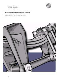
Illustration of the axle <strong>SK</strong> <strong>RB</strong> / <strong>RLB</strong> 9019 / 9022<br />
56<br />
01<br />
56.1<br />
Direction Fahrtrichtung of travel<br />
Driving direction<br />
22 / 22.1<br />
<strong>Hub</strong> Achskopf <strong>Unit</strong> <strong>SK</strong> <strong>RB</strong> / <strong>RLB</strong><br />
LH Links- / RH thread / Rechtsgewinde<br />
78.1<br />
78<br />
Achsmutter Axle nut (item (Pos. 21 21 // 22)<br />
Wheel Radkappe cap mit with O-Ring O-ring (Pos. (item 40) 40)<br />
O-ring O-Ring (item (Pos. 39.1)<br />
Brake Bremsscheibe Disc<br />
Achskopf <strong>Hub</strong> <strong>Unit</strong> <strong>SK</strong> <strong>RB</strong> INTEGRAL / <strong>RLB</strong> INTEGRAL<br />
Achsmutter Axle nut (item (Pos. 21 21 / / 22)<br />
Wheel Radkappe cap mit with O-Ring O-ring (Pos. (item 40) 40)<br />
O-ring O-Ring (item (Pos. 39.1)<br />
11396GB Edition 0606<br />
8<br />
INTEGRALBremsscheibe<br />
Brake Disc<br />
IPL_55_006_1
Installation instructions<br />
Remove brake pads<br />
Disconnect the plug connec<strong>to</strong>r from the wear indica<strong>to</strong>r and pull the<br />
ABS sensor out of the sensor bracket.<br />
Loosen the mounting bolt of the pad hold-down bracket.<br />
Pull the pad hold-down bracket out of the brake calliper<br />
Remove the hold-down spring from the brake pads and thrust plate.<br />
Push the brake calliper <strong>to</strong> the wheel rim side and pull out the brake<br />
pad.<br />
Push the brake calliper inwards and remove the brake pad with<br />
thrust plate (WABCO).<br />
Remove brake callipers<br />
Loosen and remove the retaining nuts for the brake cylinder.<br />
Remove the brake cylinder from the brake calliper.<br />
Loosen and remove the mounting bolts for the brake calliper.<br />
Remove the brake calliper from the brake backing plate.<br />
Remove <strong>Hub</strong> <strong>Unit</strong> <strong>SK</strong> <strong>RB</strong> / <strong>RLB</strong> with wheel flange and<br />
brake disc<br />
Remove the wheel cap from <strong>Hub</strong> <strong>Unit</strong> <strong>SK</strong> <strong>RB</strong> / <strong>RLB</strong>.<br />
11396GB Edition 0606<br />
9
Installation instructions<br />
Loosen axle nut and remove from the stub axle.<br />
Note:<br />
On the left-hand side as seen in the direction of travel =<br />
left-hand thread.<br />
Axle nut wrench WAF 85 (SAF Part No. 4 434 3828 00)<br />
Remove <strong>Hub</strong> <strong>Unit</strong> <strong>SK</strong> <strong>RB</strong> / <strong>RLB</strong> complete with brake disc from the<br />
stub axle.<br />
If necessary, pull <strong>Hub</strong> <strong>Unit</strong> <strong>SK</strong> <strong>RB</strong> / <strong>RLB</strong> from the stub axle using a<br />
puller.<br />
Puller (SAF Part No. 4 434 3822 00)<br />
11396GB Edition 0606<br />
Prepare stub axle<br />
Clean the contact surfaces for the <strong>Hub</strong> <strong>Unit</strong> <strong>SK</strong> <strong>RB</strong> / <strong>RLB</strong> on the stub<br />
axle and coat with SAF mounting paste.<br />
Mounting paste<br />
(tube of grease supplied or SAF Part No. 5 387 0015 06)<br />
10
Installation instructions<br />
Install <strong>Hub</strong> <strong>Unit</strong> <strong>SK</strong> <strong>RB</strong> / <strong>RLB</strong> INTEGRAL with brake disc<br />
on stub axle<br />
<strong>Hub</strong> <strong>Unit</strong> <strong>SK</strong> <strong>RB</strong> / <strong>RLB</strong> INTEGRAL (see illustration).<br />
Place a new O-ring (item 39.1) in<strong>to</strong> the O-ring groove in <strong>Hub</strong> <strong>Unit</strong><br />
<strong>SK</strong> <strong>RB</strong> / <strong>RLB</strong> INTEGRAL.<br />
item 39.1<br />
Push <strong>Hub</strong> <strong>Unit</strong> <strong>SK</strong> <strong>RB</strong> / <strong>RLB</strong> INTEGRAL on<strong>to</strong> the stub axle.<br />
Screw on the axle nut.<br />
Note:<br />
On the left-hand side as seen in the direction of travel =<br />
left-hand thread<br />
11396GB Edition 0606<br />
11
Installation instructions<br />
Tighten the axle nut <strong>to</strong> the prescribed tightening <strong>to</strong>rque, thereby<br />
turning the <strong>Hub</strong> <strong>Unit</strong> through two revolutions.<br />
Tightening <strong>to</strong>rque, see Table 1<br />
Note:<br />
On the left-hand side as seen in the direction of travel =<br />
left-hand thread<br />
Axle nut wrench WAF 85 (SAF Part No. 4 434 3828 00)<br />
item 40<br />
Install new wheel cap with O-ring in <strong>Hub</strong> <strong>Unit</strong> <strong>SK</strong> <strong>RB</strong> / <strong>RLB</strong><br />
INTEGRAL.<br />
Wheel cap with O-ring (item 40).<br />
item 56.1<br />
Install brake calliper on brake backing plate<br />
Position the brake calliper on the brake backing plate and screw in<br />
the mounting bolts for the brake calliper in the correct position.<br />
11396GB Edition 0606<br />
item 56<br />
Caution!<br />
The shoulder bolt (item 56.1) may only be screwed in<strong>to</strong> the<br />
threaded bore with the recess in the brake calliper.<br />
12
Installation instructions<br />
item 56.1<br />
Tighten mounting bolts (items 56 and 56.1) <strong>to</strong> the prescribed<br />
tightening <strong>to</strong>rque.<br />
item 56<br />
Caution!<br />
Use only new hexagon head bolts / shoulder bolts<br />
(items 56 and 56.1)!<br />
The bolts must not be oiled or greased.<br />
Tightening <strong>to</strong>rque, see Table 1<br />
Pry out the plug for the brake adjuster using a suitable screwdriver<br />
and back off the brake at the adjusting screw.<br />
Note:<br />
Insert the screwdriver between plug and seal ring.<br />
Do not place the screwdriver against the housing seal ring and pry<br />
out with force.<br />
The seal ring must not be deformed or damaged.<br />
When backing off the WABCO brake calliper, the thrust plate must<br />
be positioned with the pin <strong>to</strong> act as a twist lock for the thruster.<br />
The thruster must not turn as otherwise the bellows protective cap<br />
will be damaged<br />
Back off the brake at the hexagon of the adjuster and then turn<br />
back 1/4 turn from the end position.<br />
Inspect the brake calliper for serviceable function and serviceability<br />
of the parts by:<br />
– Checking the axial shiftability and sliding function<br />
– Checking the admissible wear clearance of the guide bolts<br />
– Checking the au<strong>to</strong>matic adjustment function<br />
– Inspecting the bellows protective caps and seals; replace the parts<br />
or the brake calliper, if necessary<br />
– If necessary, replace defective parts or the brake calliper<br />
11396GB Edition 0606<br />
13
Installation instructions<br />
Clean the slots for the brake pads and blow out.<br />
Install brake pads<br />
Push the brake calliper <strong>to</strong> one side and install the thrust plate<br />
(WABCO) and new brake pads.<br />
Install the hold-down springs over the brake pads and the thrust<br />
plate.<br />
Push the pad hold-down bracket in<strong>to</strong> the brake calliper.<br />
Screw in the mounting bolt of the pad hold-down bracket and<br />
tighten <strong>to</strong> the prescribed tightening <strong>to</strong>rque.<br />
Tightening <strong>to</strong>rque, see Table 1<br />
11396GB Edition 0606<br />
Install brake cylinder on brake calliper<br />
Inspect the condition of the seal on the brake cylinder flange and<br />
replace the seal, if necessary.<br />
Inspect the sealing surface on the brake calliper and clean,<br />
if necessary.<br />
Bolt the brake cylinder <strong>to</strong> the brake calliper and tighten the<br />
retaining nuts crosswise <strong>to</strong> the prescribed tightening <strong>to</strong>rque.<br />
Tightening <strong>to</strong>rque, see Table 1<br />
14
Installation instructions<br />
Adjust clearance by:<br />
– Filling the compressed air system <strong>to</strong> cut-off pressure and releasing<br />
the parking brake.<br />
– Adjusting the clearance with the adjuster.<br />
Install the plug or cap for the adjuster again securely.<br />
Install ABS sensor<br />
Install the ABS sensor in the sensor bracket and push up <strong>to</strong> the<br />
exciter ring.<br />
Attention, Attention!!<br />
Please ensure that the additional<br />
label ORIGINAL INTEGRAL is put<br />
next <strong>to</strong> the type plate.<br />
Be sure <strong>to</strong> quote for all later repair<br />
work!!!<br />
ORIGINAL<br />
INTEGRAL<br />
Achtung Umbau! Zur Ersatzteil-Identifikation unbedingt auf dieses Schild hinweisen.<br />
Important – <strong>Conversion</strong>! Refer <strong>to</strong> this nameplate for spare part identification.<br />
Attention modification! Il faut impérativement faire référence à cette plaque pour<br />
l’identification de la pièce de rechange.<br />
Attenzione: Modifica! Per l’identificazione del pezzo di ricambio fare riferimen<strong>to</strong> a<br />
questa targhetta.<br />
¡Atención, remodelación! Para identificar las piezas de recambio, avisar de esta placa.<br />
Ñ•ó£Å•óç! ®ç´çßÉß´„ãßÖÅ•óç! ä©˝ óãç•·óÁóüÅÎóó ïÅóÅ≠•ßù ÌÅ≠·ó<br />
ßÉ˝ïÅ·ç°˜•ß „üÅïıÖÅù·ç •Å ˘·„ ·ÅÉ°óÌü„ ≠ „üÅïÅ•óç£ ·ó©Å.<br />
Axle identification<br />
plate<br />
Caution!<br />
After completing the conversion work, check the function of the brakes on a roller dynamometer.<br />
11396GB Edition 0606<br />
15
Tightening <strong>to</strong>rques (Nm)<br />
Table 1<br />
Caution!<br />
The bolts, item 45, 56 and 56.1 must be replaced during all repair work.<br />
The bolts must not be oiled or greased.<br />
Tighten all bolts using a <strong>to</strong>rque wrench.<br />
Bolted connections Item No. Tightening <strong>to</strong>rques (Nm)<br />
Axle nuts 21 / 22 Pretightening: 150 Nm, whilst turning the<br />
hub unit evenly by 5 revolutions.<br />
Final tightening: tighten further by 30º<br />
INTEGRAL-Brake Disc<br />
1. pre-tighten diagonally with 30 Nm<br />
Double hex. bolt, 45 2. furhter tighten diagonally with <strong>to</strong>rque angle 90º<br />
socket 13, M12 x 1.5<br />
(in-service inspection <strong>to</strong>rque 150 Nm)<br />
Brake calliper on axle 56<br />
Hexagon bolt M16 x 1.5 56.1<br />
Brake chamber hex. nut<br />
M16 x 1.5<br />
290 Nm<br />
Tighten alternately and unitformly in 2 stages<br />
1. Pretightening 120 Nm<br />
2. Torque angle 210 Nm<br />
(in-service inspection <strong>to</strong>rque 210 Nm)<br />
11396GB Edition 0606<br />
16
NOTIZEN/NOTES/NOTE<br />
11396GB Edition 0606<br />
17
Soforthilfe im Pannenfall<br />
NonS<strong>to</strong>pService 24<br />
Support in the case of service<br />
SV11396GB 0606 Amendments and errors reserved © SAF<br />
·<br />
Im Servicefall wählen Sie bitte immer die Rufnummer Ihres Heimatlandes.<br />
In the case of service please always dial the number of your own country.<br />
Inland<br />
home country<br />
03 62 27 23 21<br />
0 59 33 07 07<br />
+30 21 09 40 19 80<br />
+386 26 16 58 35<br />
0 19 08 64 90<br />
2 61 10 45 06<br />
0800 72 37 37 84 / 0 73 33 80 81 58<br />
75 72 74 74<br />
9 02 18 19 92<br />
697 91 96<br />
03 88 72 06 43<br />
0 93 51 31 33<br />
+41 19 08 64 90<br />
0 87 02 42 02 37<br />
21 09 40 19 80<br />
06 13 45 17 27<br />
+386 26 16 58 35<br />
02 66 16 55 74<br />
+44 87 02 42 02 37<br />
+32 59 33 07 07<br />
+372 697 91 96<br />
+372 697 91 96<br />
+33 3 88 72 06 43<br />
+386 26 16 58 35<br />
+45 75 72 74 74<br />
+32 59 33 07 07<br />
+34 9 13 82 68 41<br />
06 18 31 98 70<br />
02 12 50 02 60<br />
+39 02 66 16 55 74<br />
+45 75 72 74 74<br />
+42 02 61 10 45 06<br />
0 26 16 58 35<br />
0 21 22 75 13 21<br />
+386 26 16 58 35<br />
www.saf-axles.com<br />
Ot<strong>to</strong> Sauer Achsenfabrik GmbH · Hauptstraße 26 · D-63856 Bessenbach<br />
Tel +49 (0) 60 95 / 301-0 · Fax +49 (0) 60 95 / 301-259 · www.saf-axles.com<br />
☎<br />
A<br />
B<br />
BG<br />
BIH<br />
CH<br />
CZ<br />
D<br />
DK<br />
E<br />
EST<br />
F<br />
FIN<br />
FL<br />
GB<br />
GR<br />
H<br />
HR<br />
I<br />
IRL<br />
L<br />
LT<br />
LV<br />
MC<br />
MK<br />
N<br />
NL<br />
P<br />
PL<br />
RO<br />
RSM<br />
S<br />
<strong>SK</strong><br />
SLO<br />
TR<br />
YU<br />
Vom Ausland<br />
from abroad<br />
+43 3 62 27 23 21<br />
+32 59 33 07 07<br />
+30 21 09 40 19 80<br />
+386 26 16 58 35<br />
+41 19 08 64 90<br />
+42 02 61 10 45 06<br />
00800 72 37 37 84 / +49 73 33 80 81 58<br />
+45 75 72 74 74<br />
+34 9 13 82 68 41<br />
+372 697 91 96<br />
+3 33 88 72 06 43<br />
+35 8 93 51 31 33<br />
+41 19 08 64 90<br />
+44 87 02 42 02 37<br />
+30 21 09 40 19 80<br />
+36 13 45 17 27<br />
+386 26 16 58 35<br />
+39 02 66 16 55 74<br />
+44 87 02 42 02 37<br />
+32 59 33 07 07<br />
+372 697 91 96<br />
+372 697 91 96<br />
+33 3 88 72 06 43<br />
+386 26 16 58 35<br />
+45 75 72 74 74<br />
+32 59 33 07 07<br />
+34 9 13 82 68 41<br />
+48 6 18 31 98 70<br />
+40 2 12 50 02 60<br />
+39 02 66 16 55 74<br />
+45 75 72 74 74<br />
+42 02 61 10 45 06<br />
+386 26 16 58 35<br />
+90 21 22 75 13 21<br />
+386 26 16 58 35