AMB-289 INSTRUCTION MANUAL I. Mechanical section ... - JUKI
AMB-289 INSTRUCTION MANUAL I. Mechanical section ... - JUKI
AMB-289 INSTRUCTION MANUAL I. Mechanical section ... - JUKI

Create successful ePaper yourself
Turn your PDF publications into a flip-book with our unique Google optimized e-Paper software.
CHAPTER !<br />
<strong>Mechanical</strong> <strong>section</strong>
!. <strong>Mechanical</strong> <strong>section</strong><br />
CONTENTS<br />
1. SPECIFICATIONS............................................................................. !- 1<br />
(1) Specifications ...................................................................................................... !- 1<br />
(2) Shapes of buttons ............................................................................................... !- 2<br />
1) Specifications for 4-holed and 2-holed buttons ........................................................................!- 2<br />
2) Specifications for shank button and marble button ..................................................................!- 2<br />
3) Specifications for stay button ...................................................................................................!- 3<br />
4) Counter button specifications ...................................................................................................!- 3<br />
(3) Configuration ....................................................................................................... !- 4<br />
2. INSTALLATION................................................................................. !- 5<br />
(1) Set-up of the table ............................................................................................... !- 5<br />
(2) Connecting the power source cord ................................................................... !- 6<br />
1) Voltage specifications...............................................................................................................!- 6<br />
2) Connecting single phase 200V, 220V, 230V and 240V ............................................................!- 6<br />
3) Connecting three phase 200V, 220V and 240V .......................................................................!- 6<br />
(3) Changing the voltage of 100 / 200V ................................................................... !- 7<br />
(4) Installing the sewing machine main unit........................................................... !- 8<br />
(5) Tilting the sewing machine head........................................................................ !- 8<br />
(6) Removing the fixed plate for transport ............................................................. !- 9<br />
(7) Installing the operation panel............................................................................. !- 9<br />
(8) Installing the air regulator ................................................................................ !- 10<br />
(9) Connecting the cords........................................................................................ !- 11<br />
(10) Managing the cord ........................................................................................... !- 12<br />
(11) Installing the eye protection cover and the finger guard............................. !- 12<br />
(12) Installing the thread stand .............................................................................. !- 13<br />
(13) Attaching the button tray ................................................................................ !- 13<br />
3. PREPARATION BEFORE OPERATION ......................................... !- 14<br />
(1) Inserting the needle .......................................................................................... !- 14<br />
(2) Threading the needle-thread............................................................................. !- 14<br />
(3) Adjusting the stay (counter) button stopper................................................... !- 15<br />
(4) Replacing the button chuck.............................................................................. !- 16<br />
(5) Set of the button neck wrapping ...................................................................... !- 17<br />
(6) Set of the sewing flat button with blindstitch ................................................. !- 17<br />
4. ADJUSTMENT OF THE SEWING MACHINE .................................. !- 18<br />
(1) Adjusting the needle and the looper ............................................................... !- 18<br />
1) Adjusting the needle bar height ..............................................................................................!- 18<br />
2) Adjusting the clearance between the needle and the looper..................................................!- 18<br />
(2) Adjusting the position of the york slide .......................................................... !- 19
(3) Adjusting the needle and the needle guide .................................................... !- 20<br />
1) Adjusting the position of the needle and the throat plate .......................................................!- 20<br />
2) Adjusting the clearance between the needle and the needle guide .......................................!- 20<br />
(4) Adjusting the thread trimmer mechanism ...................................................... !- 21<br />
1) Adjusting the position of the moving knife ..............................................................................!- 21<br />
2) Adjusting the moving knife thread separation nail ..................................................................!- 21<br />
(5) Adjusting the wiper mechanism ...................................................................... !- 22<br />
(6) Adjusting the chuck open mechanism ............................................................ !- 22<br />
5. MAINTENANCE .............................................................................. !- 23<br />
(1) Replacing the attachments ............................................................................... !- 23<br />
1) Replacing the button set pin (optional)...................................................................................!- 23<br />
2) Replacing the carrier pin ........................................................................................................!- 23<br />
3) Replacing the tongue stopper ................................................................................................!- 24<br />
(2) Replacing the fuse............................................................................................. !- 25<br />
(3) Greasing parts ................................................................................................... !- 26<br />
6. AIR CIRCUIT DIAGRAM................................................................. !- 28<br />
7. DRAWING OF THE TABLE ............................................................. !- 29<br />
(1) Table .................................................................................................................... !- 29<br />
(2) Auxiliary table .................................................................................................... !- 30
!. <strong>Mechanical</strong> <strong>section</strong><br />
1. SPECIFICATIONS<br />
(1) Specifications<br />
Model<br />
Name of model<br />
<strong>AMB</strong>-<strong>289</strong><br />
Computer-controlled, high-speed, single-thread, chainstitch, button-neck-wrapping machine<br />
Application<br />
Feature<br />
Sewing speed<br />
Button size<br />
Needle<br />
Thread take-up lever<br />
Needle throwing method<br />
Feed method<br />
Presser lifting method<br />
Cloth presser method<br />
Thread trimmer method<br />
Thread tension adjustment<br />
Dimensions<br />
Weight of head<br />
Number of data that can<br />
be stored in memory<br />
Number of times of cycle<br />
sewing<br />
Basic shape setting range<br />
Pattern selection<br />
Memory backup<br />
Sewing count<br />
Power requirements<br />
Noise<br />
Various buttons sewing (Buttons which can be sewn with the sewing machine)<br />
The machine comes standard with plural sewing patterns by computer-controlled feed, needle<br />
throwing, thread tension and thread trimmer. It can perform efficiently high-quality button sewing<br />
and a multipurpose button sewing machine that can be used as the general machine.<br />
Max. 1,800 rpm (buttons with neck wraps), 1,200 rpm (button sewing)<br />
Normal speed 1,500 rpm (buttons with neck wraps), 1,000 rpm (button sewing)<br />
Sewing buttons without button neck : 8 mm to 38 mm<br />
Sewing buttons with neck wraps<br />
: Max. 32 mm<br />
Counter button<br />
: 8 mm to 25 mm<br />
Counter button neck wrapping<br />
: Total of material and front button is up to 32 mm.<br />
SM332EXTLG-NY (Standard) #12 to #18<br />
Needle bar thread take-up lever : Stroke 60 mm<br />
Stepping motor drive<br />
Stepping motor drive<br />
Stepping motor drive<br />
Air drive<br />
Air drive<br />
Active tension (VCM) method<br />
Width : 600 x Height : 400 x Length : 600 (mm)<br />
65kg<br />
Max. 99 patterns<br />
Number of registered patterns : 20 patterns (1 cycle 30 patterns)<br />
Interval between buttonholes<br />
: 1.5 to 6.0 mm (in increments of 0.1 mm)<br />
Height of neck wraps<br />
: 0, 1.5 to 10.0 mm (in increments of 0.1 mm)<br />
Number of crossover threads<br />
: 2 to 64 threads (in increments of 2 threads)<br />
Pattern No. designation method (scroll 1 to 99 patterns)<br />
Pattern data, sewing data, cycle sewing data<br />
Number of times of sewing count method (0 to 9999) up/down<br />
Sewing counter is possible.<br />
Single phase 200V, 220V, 230V and 240V, Three phase 200V, 220V and 240V 400VA<br />
Workplace-related noise at sewing speed<br />
n = 1,800 min –1 : LPA 83 dB(A)<br />
Noise measurement according to DIN 45635-48-A-1.<br />
!– 1
(2) Shapes of buttons<br />
1) Specifications for 4-holed and 2-holed buttons<br />
A<br />
B<br />
E1<br />
G<br />
G<br />
E2<br />
G<br />
E3<br />
G<br />
E3<br />
B<br />
C<br />
D<br />
D<br />
F<br />
F<br />
F<br />
H<br />
H<br />
H<br />
A : Buttonhole diameter Needle used : ø 1.5 mm or more when using #12 to #16<br />
Needle used : ø 2 mm or more when using #16 to #18<br />
B : Distance between buttonholes 1.5 to 6.0 mm (in increments of 0.1 mm)<br />
C : Location of buttonholes All holes must be located equidistant from the center of each button.<br />
D : Outside diameter<br />
Min. outside diameter : ø 8 mm<br />
Max. outside diameter : ø 32 mm<br />
Line height : within ± 0.25 mm<br />
E1 : Button with a round edge R (roundness) of button edge must be a 3 mm radius or less.<br />
E2 : Button with a V-shaped edge Within 120˚ angle<br />
E3 : Button with an angular edge The thickness must be 5 mm or less.<br />
F : Bulge<br />
5 mm or less<br />
G: Area around buttonholes Must be smooth<br />
H : Thickness of button<br />
8 mm or less<br />
2) Specifications for shank button and marble button<br />
F<br />
A: Buttonhole diameter ø 1.5 mm or more<br />
B: Thickness of button 6.8 mm or less<br />
C: Distance from the Shank button :<br />
E<br />
B<br />
bottom of the button 1 mm to 6 mm<br />
head to the center Marble button :<br />
A<br />
C<br />
D<br />
of the buttonhole<br />
1.5 mm or more<br />
D: Length of shank 8 mm or less<br />
E: Height of the 3.5 mm or less<br />
F<br />
straight <strong>section</strong> on the000<br />
side face of button<br />
A<br />
E<br />
C<br />
B<br />
F: Outside diameter Min. outside diameter :<br />
ø 8 mm<br />
Max. outside diameter :<br />
ø 32 mm<br />
G<br />
G: Distance from the center 2 mm or less<br />
of the hole to the button<br />
edge<br />
When the button loader is used, there are cases where the buttons cannot be used due to the shape.<br />
So, be careful.<br />
!– 2
3) Specifications for stay button<br />
Buttonhole<br />
diameter<br />
Right<br />
side<br />
1 mm or * 1<br />
less<br />
Commendable dimension<br />
Outside Buttonhole Buttonhole Thickness<br />
diameter diameter pitch of button<br />
Type A 8.5mm 2.5mm 3.1mm 2.0mm<br />
Type B 10.2mm 3.2mm 4.0mm 2.0mm<br />
* 1 For the stay buttons, use those, the amount of<br />
convex on the right side of which is 1 mm or<br />
less.<br />
Buttonhole pitch<br />
Outside<br />
diameter<br />
Thickness of button<br />
4) Counter button specifications<br />
A<br />
B<br />
E1<br />
G<br />
G<br />
G<br />
E2<br />
G<br />
E2<br />
B<br />
C<br />
D<br />
D<br />
F<br />
F<br />
F<br />
H<br />
H<br />
H<br />
Commendable dimension<br />
A : Buttonhole diameter Needle used : ø 1.5 mm or more when using #12 to #16<br />
Needle used : ø 2 mm or more when using #16 to #18<br />
B : Distance between buttonholes 1.5 to 6.0 mm<br />
C : Location of buttonholes All holes must be located equidistant from the center of each button.<br />
D : Outside diameter<br />
Min. outside diameter : ø 8 mm<br />
Max. outside diameter : ø 25 mm<br />
E1 : Button with a round edge R (roundness) of button edge must be a 2 mm radius or less.<br />
E2 : Button with an angular edge The thickness must be 5 mm or less.<br />
F : Height of button edge 2 mm or less<br />
G: Area around buttonholes Must be smooth<br />
H : Thickness of button<br />
5 mm or less<br />
!– 3
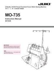
(3) Configuration<br />
2<br />
7<br />
6<br />
3<br />
1<br />
4<br />
5<br />
<strong>AMB</strong>-<strong>289</strong> consists of the following components.<br />
1 Power ON/OFF switch<br />
2 Machine head(<strong>AMB</strong>-<strong>289</strong>)<br />
3 Operation panel(IP-200D)<br />
4 Control box(MC-640)<br />
5 Foot pedal<br />
6 Start switch<br />
7 Thread stand device<br />
!– 4
2. INSTALLATION<br />
WARNING :<br />
To prevent possible accidents caused by the fall of the sewing machine, perform the work by two persons<br />
or more when the machine is moved.<br />
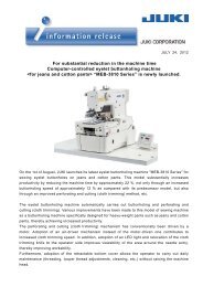
(1) Set-up of the table<br />
!1<br />
8<br />
6<br />
7<br />
5<br />
1<br />
!3<br />
2<br />
9<br />
4<br />
!2<br />
3<br />
9<br />
!0<br />
1) Fix control box 2, power switch 3, auxiliary table !3 and start switch 4 to table 1.<br />
Note) Install auxiliary table !3 before installing start switch 4.<br />
2) Fix the cables of power switch 3 and start switch 4 with staples.<br />
3) Pass arm stay fixing screws !1(3 pcs.) through arm stay 5, instal on the table, and fix them with<br />
nuts !2.<br />
4) Drive pins 6 to the table, and insert rubber cushions 7.<br />
5) Fix head support bar 8 on table 1.<br />
6) Connect the pedal (left-hand side) and control box pedal sensor !0with connecting rod 9 supplied<br />
as accessories.<br />
Adjust the positions of the pedals so that connecting rods 9 and control box 2 do not come in<br />
contact with each other.<br />
!– 5
(2) Connecting the power source cord<br />
1) Voltage specifications<br />
Voltage caution<br />
seal<br />
Power source specifications are indicated on the<br />
voltage indication seal. (3-phase type only)<br />
For other type machines, power source<br />
specifications are indicated on the voltage caution<br />
seal and the rating label.<br />
Connect the cord in accordance with the<br />
specifications.<br />
Rating label<br />
Voltage indication seal<br />
(3-phase type only)<br />
2) Connecting single phase 200V, 220V, 230V and 240V<br />
Connect so as to supply the power to the white wire and the black wire as shown in the illustration.<br />
Light blue<br />
Light blue<br />
Table<br />
Control box<br />
Green/Yellow<br />
Brown<br />
Brown<br />
Green/Yellow<br />
Plug<br />
Power switch<br />
Power source cord<br />
Brown<br />
Light<br />
blue<br />
Green/<br />
Yellow<br />
AC200 V<br />
AC220 V<br />
AC230 V<br />
AC240 V<br />
GND<br />
3) Connecting three phase 200V, 220V and 240V<br />
White<br />
White<br />
Table<br />
Control box<br />
Green/Yellow<br />
Black<br />
Red<br />
Black<br />
Red<br />
Green/Yellow<br />
Plug<br />
Red<br />
White<br />
Black<br />
Green/<br />
Yellow<br />
AC200 V<br />
AC220 V<br />
AC240 V<br />
GND<br />
Power switch<br />
Power source cord<br />
1. Never use under the wrong voltage and phase.<br />
2. When changing the voltage, refer to the item of "Changing the voltage of 100 / 200V".<br />
!– 6
(3) Changing the voltage of 100 / 200V<br />
WARNING :<br />
To prevent personal injuries caused by electric shock hazards or abrupt start of the sewing machine,<br />
carry out the work after turning OFF the power switch and a lapse of 5 minutes or more. To prevent<br />
accidents caused by unaccustomed work or electric shock, request the electric expert or engineer of<br />
our dealers when adjusting the electrical components.<br />
It is adaptable to the voltage of single phase 100V to 120V/3-phase 200V to 240V by changing the<br />
voltage changeover connector mounted on FLT p.c.b.<br />
(Caution) When the changing procedure is wrong, the control box will be broken. So, be very<br />
careful.<br />
Changing procedure of the changeover connector<br />
1. Turn OFF the power source with the power<br />
switch after confirming that the sewing machine<br />
has stopped.<br />
2. Draw out the power cord from the power plug<br />
socket after confirming that the power switch is<br />
turned OFF. Then wait for five minutes or more.<br />
3. Remove the front cover.<br />
4. Remove four screws fixing the rear cover of the<br />
control box and slowly open the rear cover.<br />
A<br />
B<br />
C<br />
WHITE<br />
BLACK<br />
RED<br />
GREEN/<br />
YELLOW<br />
WHITE<br />
BLACK<br />
RED<br />
GREEN/<br />
YELLOW<br />
WHITE<br />
BLACK<br />
RED<br />
GREEN/<br />
YELLOW<br />
WHITE<br />
BLACK<br />
RED<br />
GREEN/<br />
YELLOW<br />
GREEN/<br />
YELLOW<br />
1<br />
(Plug side)<br />
(Plug side)<br />
WHITE<br />
BLACK<br />
RED<br />
WHITE<br />
BLACK<br />
RED<br />
GREEN/<br />
YELLOW<br />
(Plug side)<br />
A. In case of using with 3-phase 200V to 240V<br />
• Changing the changeover connector<br />
Connect to 200V the 100/200V changeover<br />
connector of FLT p.c.b. 1 located on the side<br />
of the Box Side of the control box.<br />
• Connect the crimp style terminal of AC input cord<br />
to the power plug as shown in the figure.<br />
B. In case of using with single phase 100V to 120V<br />
• Changing the changeover connector<br />
Connect to 100V the 100/200V changeover<br />
connector of FLT p.c.b. 1 located on the side<br />
of the Box Side of the control box.<br />
• Connect the crimp style terminal of AC input cord<br />
to the power plug as shown in the figure.<br />
(Caution) Securely perform the insulation<br />
treatment to the red terminal which<br />
is not used with insulation tape or<br />
the like.<br />
(When the insulation is insufficient,<br />
there is a danger of electric shock or<br />
leakage current.)<br />
C. In case of using with single phase 200V to 240V<br />
• Changing the changeover connector<br />
Connect to 200V the 100/200V changeover<br />
connector of FLT p.c.b. 1 located on the side<br />
of the Box Side of the control box.<br />
• Connect the crimp style terminal of AC input cord<br />
to the power plug as shown in the figure.<br />
(Caution) Securely perform the insulation<br />
treatment to the red terminal which<br />
is not used with insulation tape or the<br />
like.<br />
(When the insulation is insufficient,<br />
there is a danger of electric shock or<br />
leakage current.)<br />
5. Check that the change has been performed<br />
without fail before closing the rear cover.<br />
6. Be careful that the cord is not pinched between<br />
the rear cover and the control box main unit.<br />
Close the rear cover while pressing the lower<br />
side of rear cover, and tighten four screws.<br />
!– 7
(4) Installing the sewing machine main unit<br />
WARNING :<br />
To prevent possible accidents caused by the fall of the sewing machine, perform the work by two persons<br />
or more when the machine is moved.<br />
Adjust the sewing machine head to the hole of arm<br />
stay, and insert shaft 1 . Fix shaft 1 with screws<br />
2 in the state that the end faces of shaft 1 are<br />
protruded on the both sides.<br />
Be careful that wiring and air pipe<br />
coming out from the bottom face of<br />
the sewing machine are not crushed.<br />
2 1<br />
(5) Tilting the sewing machine head<br />
WARNING :<br />
When tilting/raising the sewing machine head, perform the work so as not to allow your fingers to be<br />
caught in the machine. In addition, to avoid possible accidents caused by abrupt start of the machine,<br />
turn OFF the power to the machine before starting the work.<br />
When tilting the sewing machine head, tilt quietly<br />
the sewing machine until head support bar <br />
comes in contact with it.<br />
<br />
1. Make sure that sewing machine<br />
head support bar is placed on<br />
the table before tilting the sewing<br />
machine.<br />
2. To protect fall-down, be sure to<br />
tilt the sewing machine in a level<br />
place.<br />
3. Keep the table in the state that<br />
anything is not put on the top<br />
surface of table<br />
!– 8
(6) Removing the fixed plate for transport<br />
2<br />
1<br />
Remove fixed screw 1 and remove fixed plate for<br />
transport 2.<br />
Fixed screw 1 and fixed plate for<br />
transport 2 are necessary when<br />
transporting with the machine head<br />
single unit. So, keep them with care.<br />
[Reference]<br />
3<br />
2<br />
¡In case of the complete transport<br />
In case of the complete transport, fix the sewing<br />
machine to the table with screw 1, two flat washers<br />
2 and nut 3 supplied as accessories in order to<br />
safely transport the sewing machine.<br />
1<br />
(7) Installing the operation panel<br />
1<br />
Fix operation panel attaching plate on the table<br />
with woodscrew and pass the cable through hole<br />
in the table.<br />
2<br />
3<br />
!– 9
(8) Installing the air regulator<br />
3<br />
2<br />
1<br />
!1<br />
4<br />
!0<br />
8<br />
5<br />
6<br />
7<br />
9<br />
1) Install filter installing plate 1 on the right side of the stand side support with screw 3.<br />
2) Fix air regulator 2 on filter installing plate 1 with screw 4.<br />
3) Fix elbow union 5 on the right <strong>section</strong> of air regulator 2.<br />
4) Insert air hose 6 into elbow union 5.<br />
5) Insert reducing union T 7 into the top end of the air hose, and insert stop plug 8 into the hole of ø6.<br />
Reference<br />
Use the branch <strong>section</strong> (ø6) of reducing union T 7 when using the air gun.<br />
Air gun set (G57602540A0) is available as optional.<br />
6) Insert air tube 9 coming from the main unit of machine head into reducing union T 7.<br />
7) Insert pressure sensor relay cord !0 into connector !1 of air regulator 2.<br />
8) Winding pressure sensor relay cord !0 around air tube 9, insert it into the control box (CN41).<br />
9) Supply air, and adjust the air pressure to 0.5 Mpa.<br />
!– 10
(9) Connecting the cords<br />
Perform the connection of the cords as shown in the figure below.<br />
Sewing machine head<br />
CN14<br />
CN16<br />
CN16<br />
SDC circuit board<br />
CN14<br />
CN33<br />
CN38<br />
Start<br />
switch<br />
CN38<br />
CN39<br />
CN39<br />
CN40<br />
Operation panel<br />
MAIN<br />
circuit<br />
board<br />
CN33<br />
CN40<br />
CN41<br />
CN43<br />
CN44<br />
CN43<br />
CN44<br />
CN34<br />
CN34<br />
Filter regulator<br />
CN41<br />
SDC circuit board<br />
CN14<br />
CN16<br />
1<br />
Cord<br />
clamp A<br />
1) Pass 5 cords (CN39, 40, 41, 43 and 44)<br />
connecting to the right side among the cords<br />
connecting to MAIN circuit board through cord<br />
clamp A as shown in the figure, and connect<br />
them to the respective connectors. Connect<br />
CN38 to the connector without passing through<br />
cord clamp A.<br />
2) Directly connect two cords connecting to the left<br />
side of MAIN circuit board to CN33 and CN34.<br />
3) Connect the cords connecting to SDC circuit<br />
board directly to CN14 and CN16.<br />
4) Fix the earth wire with the setscrew .<br />
!– 11
(10) Managing the cord<br />
1) Slowly tilting the sewing machine, check that the cords are not forcibly pulled.<br />
2) Fix the cords with cord setting plate as shown in the figure.<br />
When you tilt the sewing machine, make sure that the sewing machine head support<br />
bar is placed on the table.<br />
2<br />
1<br />
(11) Installing the eye protection cover and the finger guard<br />
WARNING :<br />
Be sure to attach this cover to protect the eyes from the disperse of needle breakage.<br />
1<br />
Be sure to install eye protection cover 1 and finger<br />
guard 2, and use the sewing machine.<br />
2<br />
!– 12
(12) Installing the thread stand<br />
2<br />
1) Assemble the thread stand, and set it in the<br />
hole in the top right corner of the machine table.<br />
2) Tighten locknut to fix the thread stand.<br />
3) When ceiling wiring is possible, pass the power<br />
cable through spool rest rod .<br />
1<br />
(13) Attaching the button tray<br />
1) Fix base on the table with wood screw .<br />
2) Insert button tray in the hole of base and<br />
fix it with setscrew after adjusting the position<br />
to that where the button can be taken with ease.<br />
It is possible to change the loader set<br />
position as well. It is recommended<br />
<br />
<br />
<br />
Reference<br />
to perform positioning them<br />
together.<br />
(Memory switch U04)<br />
<br />
!– 13
3. PREPARATION BEFORE OPERATION<br />
(1) Inserting the needle<br />
WARNING :<br />
To protect against possible personal injury due to abrupt start of the machine, be sure to start the<br />
following work after turning the power off and ascertaining that the motor is at rest.<br />
1<br />
Hold needle with its recessed part facing toward<br />
side "A" as observed from the front of the sewing<br />
machine, insert the needle into the needle hole of<br />
needle bar until it will go no further, and tighten<br />
setscrew 1 with a flat-blade screwdriver.<br />
Use a SM332EXTLG-NY(#11 to #18).<br />
When attaching the needle, turn OFF<br />
the power to the motor.<br />
A<br />
2<br />
3<br />
Reference<br />
Attach stop plug 2 supplied as<br />
accessories (insert magnet 3<br />
supplied as accessories into the<br />
top end) to the needle. It is<br />
recommended to confirm that the<br />
needle is vertical.<br />
(2) Threading the needle-thread<br />
WARNING :<br />
To protect against possible personal injury due to abrupt start of the machine, be sure to start the<br />
following work after turning the power off and ascertaining that the motor is at rest.<br />
Pass the needle thread in the order 1 to !3 as shown in the figures.<br />
2<br />
1<br />
3<br />
4<br />
9<br />
!0<br />
5<br />
7<br />
!1<br />
8<br />
!2<br />
6<br />
!3<br />
!– 14
(3) Adjusting the stay (counter) button stopper<br />
WARNING :<br />
To protect against possible personal injury due to abrupt start of the machine, be sure to start the<br />
following work after turning the power off and ascertaining that the motor is at rest.<br />
Loosen screws 3 and adjust so that the clearance<br />
between stopper 1 and pin 2 is 0.5 to 1 mm with<br />
the button used set. Then fix the stopper.<br />
6<br />
4<br />
5<br />
0.5 to 1mm<br />
1<br />
2<br />
3<br />
1. The size applicable to the stay<br />
button is ø8 to ø25, and the<br />
thickness is 2 mm or less.<br />
2. Feed plate is made so as to make<br />
it easy to set the stay button of ø8<br />
to ø10. Replace the feed plate with<br />
the feed plate for counter button<br />
when using the button which is not<br />
clamped with stay button clamps<br />
5 and 6, or using the button, the<br />
needle entry position of which is<br />
not fit to the window of gauge 4.<br />
[Reference]<br />
Counter button B set<br />
(40021447)<br />
6<br />
To change the feed plate to the feed plate for<br />
counter button, there are two kinds of methods ;<br />
changing as a set and replacing the<br />
components.<br />
4<br />
5<br />
¡In case of replacing as a set<br />
1) Purchase the set (40020807) of feed plate<br />
for counter button. Loosen two screws 8<br />
and replace the feed plate.<br />
7<br />
¡In case of replacing the components<br />
6<br />
5<br />
1) Purchase the counter button B set<br />
(40021447), loosen two screws 8, and<br />
remove the feed plate from the machine<br />
7<br />
head.<br />
2) Replace the components 4, 5, 6, and 7<br />
with counter button B set (40021447).<br />
4<br />
8<br />
8<br />
3<br />
1. Maximum size to be applied is<br />
ø25.<br />
2. When installing the feed plate,<br />
1<br />
insert it until it goes no further<br />
and fix it.<br />
!– 15
(4) Replacing the button chuck<br />
WARNING :<br />
To protect against possible personal injury due to abrupt start of the machine, be sure to start the<br />
following work after turning the power off and ascertaining that the motor is at rest.<br />
1<br />
When replacing chuck 1, loosen screws 2 and<br />
replace it with exclusive screwdriver 3 supplied as<br />
accessories.<br />
3<br />
2<br />
<br />
Part No. Description Outside diameter of button that can Remarks<br />
be used<br />
40020932 Button chuck (small) ø 8 to 16 mm Accessory<br />
40020931 Button chuck (medium) (standard) ø 14 to 25 mm Installed on<br />
machine head<br />
40020930 Button chuck (large) ø 21 to 38 mm Accessory<br />
!– 16
(5) Set of the button neck wrapping<br />
2<br />
When performing the button neck wrapping process<br />
1<br />
Groove<br />
A<br />
Groove<br />
B<br />
of stay (counter) button, use the button neck<br />
wrapping attachment (accessories) 1.<br />
Loosen screws 2 and move holder plate 3 to and<br />
fro to perform the adjustment of the height of button<br />
neck wrapping attachment.<br />
Groove B<br />
3<br />
Height of<br />
Confirm that button neck wrapping<br />
positioning grooves A and B are<br />
straight front and rear.<br />
Groove A<br />
button neck<br />
wrapping<br />
[Setting procedure of the button neck wrapping<br />
attachment]<br />
Insert convex 4 of the attachment to concave 5 of<br />
the feed plate at the time of the button neck wrapping<br />
5<br />
process pattern.<br />
4<br />
(6) Set of the sewing flat button with blindstitch<br />
2<br />
1<br />
When performing the sewing flat button with<br />
blindstitch, insert underplate spacer A 1 supplied<br />
as accessories (Part No. : 40020764) to the pin<br />
position. In addition, fix it with screws 2 when using<br />
it always.<br />
Select and use a proper underplate spacer from<br />
among the underplate spacers below according to<br />
the thickness of cloth.<br />
Discription<br />
UNDER_PLATE_SPACER A<br />
UNDER_PLATE_SPACER B<br />
UNDER_PLATE_SPACER C<br />
Thickness<br />
t=1.6<br />
t=2.0<br />
t=2.6<br />
Part No.<br />
40020764<br />
40020769<br />
40020770<br />
Remarks<br />
Accessory<br />
Optional<br />
Optional<br />
!– 17
4. ADJUSTMENT OF THE SEWING MACHINE<br />
(1) Adjusting the needle and the looper<br />
1) Adjusting the needle bar height<br />
1<br />
Use the timing gauge supplied as accessories.<br />
Loosen screw 1 and adjust so that plane A in case<br />
of SM332EXTLG-NY (standard needle) or plane B<br />
in case of SM332SUPLG-NY aligns with the height<br />
of the throat plate when the needle bar comes down<br />
to the lowest position.<br />
Marker<br />
line<br />
To align<br />
29.6mm<br />
A<br />
B<br />
34.6mm<br />
Perform the adjustment at the needle<br />
rocking origin (marker line).<br />
[Needle list]<br />
<strong>JUKI</strong> Part No.<br />
Needle Part No.<br />
MSM3AAN1100 NEEDLE SM332EXTLG-NY #11<br />
MSM3AAN1200 NEEDLE SM332EXTLG-NY #12<br />
MSM3AAN1400 NEEDLE SM332EXTLG-NY #14<br />
MSM3AAN1600 NEEDLE SM332EXTLG-NY #16<br />
MSM3AAN1800 NEEDLE SM332EXTLG-NY #18<br />
MSM3ABN1100 NEEDLE SM332SUPLG-NY #11<br />
MSM3ABN1200 NEEDLE SM332SUPLG-NY #12<br />
MSM3ABN1400 NEEDLE SM332SUPLG-NY #14<br />
MSM3ABN1600 NEEDLE SM332SUPLG-NY #16<br />
MSM3ABN1800 NEEDLE SM332SUPLG-NY #18<br />
2) Adjusting the clearance between the needle and the looper<br />
Use the timing gauge supplied as accessories.<br />
Loosen two screws 1, move looper 2 and adjust<br />
by loosening screw 4 so that the clearance<br />
32.6mm<br />
<br />
<br />
37.6mm<br />
between the needle and the blade tip of looper is<br />
0.05 to 0.1 mm when plane C in case of<br />
SM332EXTLG-NY (standard needle) or plane D in<br />
case of SM332SUPLG-NY aligns with the height<br />
of the needle bar.<br />
In addition, adjust so that the left position of<br />
needle 3 aligns with the top end of looper 2 as<br />
observed from the front.<br />
0.05 to 0.1mm<br />
3<br />
2<br />
To align<br />
2<br />
1 4<br />
!– 18
(2) Adjusting the position of the york slide<br />
1<br />
0 to 0.2mm<br />
0.2 to 0.4mm<br />
Fig. 1<br />
1) The position of york slide 1 has been factoryassembled<br />
so that the clearance between york<br />
slide 1 and the needle is longitudinally 0.2 to<br />
0.4 and laterally 0 to 0.2 mm when the needle<br />
bar comes to the lowest position.<br />
(Refer to Fig. 1.)<br />
2) Adjust the lateral position of york slide 1 by<br />
loosening setscrews 2 and moving york slide<br />
1 laterally.<br />
3) Adjust the longitudinal position of york slide 1<br />
2<br />
by loosening setscrew 3 and moving york slide<br />
cam 4 longitudinally. The motion timing of york<br />
slide cam 4 at this time is adjusted by making<br />
the engraved marker line on york slide cam 4<br />
1<br />
directly below and tightening the cam with<br />
setscrew 3 when the needle bar is at the lowest<br />
position.<br />
4) Timing of the york slide motion is performed in<br />
the order that the york slide moves from the<br />
left to the right and starts retracting immediately<br />
after the blade tip of looper has passed the<br />
triangle of the thread.<br />
(Position where the needle bar goes up<br />
Approx. 6mm<br />
approximately 6 mm from the lowest position)<br />
5) Loosen setscrews 7 in york slide triangle cam<br />
6 and turn the cam in the direction of rotation<br />
to perform this adjustment.<br />
3<br />
Reference<br />
Marks made by the electron pen have<br />
been put on york slide cam 4 and<br />
york slide triangle cam 5 at the time<br />
of delivery from factory. Make them<br />
as the standard of timing adjustment.<br />
5<br />
6<br />
4<br />
6) For the locus of york slide motion, loosen<br />
setscrew 4 in york slide cam 5 and turn the<br />
cam in the direction of rotation to adjust so that<br />
the locus becomes a triangle while keeping the<br />
clearance (0 to 0.2 mm) between the needle<br />
and the york slide when the needle goes up.<br />
Blade tip of looper<br />
Locus of york slide<br />
!– 19
(3) Adjusting the needle and the needle guide<br />
1) Adjusting the position of the needle and the throat plate<br />
1<br />
Loosen screws 1 and adjust the throat plate so<br />
that the needle enters the center of the needle hole.<br />
Center<br />
2) Adjusting the clearance between the needle and the needle guide<br />
Loosen screw 1 and adjust so that the clearance<br />
between needle guide 2 and the needle is 0 to 0.1<br />
mm at the lowest position of the needle bar.<br />
1<br />
2<br />
0 to 0.1mm<br />
!– 20
13 to 14 mm<br />
(4) Adjusting the thread trimmer mechanism<br />
1) Adjusting the position of the moving knife<br />
First adjustment<br />
3<br />
Second adjustment<br />
0<br />
1<br />
2<br />
4<br />
5<br />
7 3 to 5 mm<br />
1 2 3<br />
[Waiting position]<br />
1. Loosen screws 1 and close the clearance<br />
with stopper 2 so that the dimension<br />
between the edge of fixed knife link 3<br />
and the groove end of throat plate is 13<br />
to 14 mm. Then fix screws 1.<br />
[Thread trimming position]<br />
1. Adjust the clearance between the blade point of<br />
moving knife 7 and the right end of the slot of<br />
throat plate is 3 to 5 mm in the state that air only<br />
is ON (solenoid valve No. 14), loosen screws 5,<br />
actuate the cylinder, and fix screws 5 in the state<br />
that the clearance is closed.<br />
2. After the adjustment, check that moving knife link<br />
4 smoothly moves.<br />
6<br />
When the work is<br />
completed, do not<br />
forget to perform the<br />
release of lock 6 of<br />
the solenoid valve.<br />
2) Adjusting the moving knife thread separation nail<br />
Top end of thread separation nail<br />
Bend thread separation nail using a screwdriver<br />
or the like and adjust so that a clearance of 0.5 to<br />
0.5 to 0.7mm<br />
0.7 mm should be provided between thread<br />
1<br />
separation nail and looper .<br />
2<br />
!– 21
(5) Adjusting the wiper mechanism<br />
8<br />
9<br />
!0<br />
4<br />
6<br />
7<br />
5<br />
3<br />
1<br />
1) Turn OFF the air, and draw wiper 1 until it<br />
goes no further.<br />
2) Adjust wiper cylinder installing bases A 3 and<br />
B 4 with the respective setscrews 5 and 6<br />
so that the vertical clearance between needle<br />
tip 2 and the top surface of wiper 1 is 3 to 5<br />
mm and the lateral dimension between<br />
needle tip 2 and the thread holding <strong>section</strong><br />
of wiper 1 is 6 to 8 mm at the sewing machine<br />
stop position (needle bar upper dead point).<br />
3) Fix spring A 7 so that wiper 1 and spring A<br />
7 equally come in contact with each other<br />
on the plane within the range of the stroke of<br />
cylinder 8.<br />
4) Adjust the holding force of thread with spring<br />
B 9.<br />
5) To adjust the holding force, loosen screw !0<br />
and adjust so that thread slips off with the<br />
force of approximately 20 to 25g when<br />
polyester spun thread #50 is held.<br />
2<br />
3 to 5mm<br />
1<br />
6 to 8mm<br />
(6) Adjusting the chuck open mechanism<br />
3<br />
1<br />
When the mode is changed over to the manual<br />
button control mode, raise hook A 1 to decrease<br />
the open amount. Adjust the open amount by<br />
loosening screws 2 and sliding hook B 3 to the<br />
right and left.<br />
2<br />
When the mode is changed over to<br />
the button loader motion mode, do<br />
not forget to release hook A 1.<br />
!– 22
5. MAINTENANCE<br />
(1) Replacing the attachments<br />
1) Replacing the button set pin (optional)<br />
1<br />
2<br />
B<br />
When replacing button set pin 2, loosen knob 1<br />
and replace it. However, when replacing the set pin<br />
with those below, remove knob 1 and install it in<br />
the screw hole on side B.<br />
1 2 3 4<br />
4<br />
3<br />
0.3 to<br />
0.7 mm<br />
No. Part No. Description<br />
1 17974056 Set pin for marble button<br />
2 17974254 Set pin for shank button<br />
(ø 1.5 to ø 2.0)<br />
3 17974452 Set pin for shank button<br />
(ø 2.0 or more)<br />
4 40023428 Set pin for metallic button<br />
2) Replacing the carrier pin<br />
When replacing carrier pin 4, loosen screws 3 and replace it.<br />
At this time, adjusdt the height of the carrier pin to 0.3 to 0.7 mm from the top surface of the set pin.<br />
<br />
Button carrier (for 4-holed button)<br />
Button carrier (for 2-holed button)<br />
1 2 3 4 5<br />
a<br />
a<br />
a<br />
a<br />
a<br />
a<br />
a<br />
a<br />
ø b<br />
ø b<br />
ø b<br />
ø b<br />
ø b<br />
Stamp Part No. Dimensions Stamp Part No. Dimensions Stamp Part No. Dimensions Stamp Part No. Dimensions Stamp Part No. Dimensions<br />
a 2.0<br />
a 2.8<br />
A 17856600<br />
D 17856907<br />
b 1.0<br />
b 1.2<br />
a 2.4<br />
a 2.8<br />
B 17856709<br />
E 17857004<br />
b 1.2<br />
b 1.4<br />
a 2.6<br />
a 3.0<br />
C 17856808<br />
F 17857103<br />
b 1.2<br />
b 1.2<br />
a 3.0<br />
F1 17857202<br />
b 1.4<br />
a 3.2<br />
G 17857301<br />
b 1.4<br />
Standard spec a 3.4<br />
H 17857400 b 1.4<br />
a 3.6<br />
J 17857509<br />
b 1.4<br />
K 17857608<br />
K1 17857707<br />
L 17857806<br />
a 4.0<br />
a 2.0<br />
a 4.0<br />
M 17858002<br />
U 17858705<br />
b 1.4<br />
b 1.0<br />
b 1.4<br />
a 4.0<br />
a 2.4<br />
a 4.2<br />
N 17858101<br />
V 17858804<br />
b 1.8<br />
b 1.2<br />
b 1.4<br />
a 5.0<br />
a 2.6<br />
a 4.4<br />
P 17858200<br />
W 17858903<br />
b 1.8<br />
b 1.2<br />
b 1.4<br />
Q 17858309<br />
a 2.8<br />
a 4.6<br />
X 17859000<br />
b 1.2<br />
b 1.4<br />
R 17858408<br />
a 3.0<br />
a 4.8<br />
Y 17859109<br />
b 1.2<br />
b 1.4<br />
S 17858507<br />
a 3.2<br />
a 5.0<br />
Z 17859208<br />
b 1.4<br />
b 1.4<br />
T<br />
Standard spec a 3.4<br />
17858606 b 1.4<br />
!– 23
3) Replacing the tongue stopper<br />
2<br />
When using the standard 4-holed tongue (Part No.<br />
25006602) of the former <strong>AMB</strong>-189N, replace the<br />
tongue stopper guide together.<br />
1<br />
1) Replacing the tongue<br />
Remove screws 1 and replace tongue 2.<br />
5<br />
4<br />
2) Replacing the tongue stopper guide<br />
Remove screws 3 and replace tongue stopper<br />
guide 4 with tongue stopper guide B (Part No. :<br />
40020763) 5 supplied as accessories.<br />
3<br />
3) Finally, perform the change of memory switch<br />
level K12.<br />
!– 24
(2) Replacing the fuse<br />
WARNING :<br />
1. To avoid electrical shock hazards, turn OFF the power and open the control box cover after about<br />
five minutes have passed.<br />
2. Open the control box cover after turning OFF the power without fail. Then, replace with a new fuse<br />
with the specified capacity.<br />
1<br />
2<br />
3<br />
The machine uses the following three fuses :<br />
For pulse motor power supply protection<br />
5A (time-lag fuse)<br />
For solenoid and pulse motor power supply<br />
protection<br />
3.15A (time-lag fuse)<br />
For control power supply protection<br />
2A (fast-blow type fuse)<br />
!– 25
(3) Greasing parts<br />
WARNING :<br />
Turn OFF the power before starting the work so as to prevent accidents caused by abrupt start of the<br />
sewing machine.<br />
Periodically perform grease-up every 6 months as a standard, or perform grease-up when<br />
(grease-up time) is displayed on the operation panel.<br />
There are three kinds of the exclusive greases supplied as accessories.<br />
Grease in grease tube (green, Part No. 13525506)<br />
Apply grease to rack, gear and cam <strong>section</strong>.<br />
1) Remove the rear cover, and apply grease to<br />
rack and gear <strong>section</strong> of Y top feed.<br />
Greasing <strong>section</strong><br />
of rack and gear<br />
Greasing <strong>section</strong> of<br />
rack on the front side<br />
2) Remove the rear cover and the side cover,<br />
and apply grease to rack and gear <strong>section</strong> of<br />
Y bottom feed.<br />
• Move the bottom unit to the extreme front,<br />
and apply grease to the front <strong>section</strong> of the<br />
rack <strong>section</strong>.<br />
Greasing <strong>section</strong> of<br />
rack on the rear side<br />
• Move the bottom unit to the extreme rear, and<br />
apply grease to the rear <strong>section</strong> of the rack<br />
<strong>section</strong>.<br />
!– 26
3) Apply grease to the york slide cam and the<br />
york slide triangle cam <strong>section</strong>s.<br />
• Tilt the machine head<br />
• Remove the looper cover.<br />
• Turning the hand pulley, apply grease to the<br />
lateral cam <strong>section</strong>.<br />
For the greasing <strong>section</strong> of the yoke<br />
slide cam, use grease in <strong>JUKI</strong> grease<br />
A tube (white, Part No. 40006323).<br />
Greasing<br />
<strong>section</strong> of the<br />
yoke slide<br />
triangle cam<br />
Greasing<br />
<strong>section</strong> of the<br />
yoke slide cam<br />
Grease in <strong>JUKI</strong> grease B tube (white, Part No. 40013640)<br />
Remove the top cover and apply grease to the worm <strong>section</strong>.<br />
Worm and worm<br />
wheel <strong>section</strong><br />
• Use the groove of top surface of worm, turning<br />
with the flatblade screwdriver, apply grease<br />
to moving parts of the worm and worm wheel.<br />
Grease in <strong>JUKI</strong> grease A tube (white, Part No. 40006323)<br />
Apply grease to other parts such as rotation fulcrum <strong>section</strong>, link moving <strong>section</strong>, etc.<br />
(Caution) 1. When applying grease, apply new grease after carefully wiping old grease with a<br />
piece of cloth or the like.<br />
2. When the air gun or the like is blown to the greasing parts and the grease is<br />
scattered, perform grease-up again.<br />
!– 27
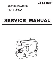
6. AIR CIRCUIT DIAGRAM<br />
No. PART NO. DESCRIPTION Q'TY<br />
1 40019187 FILTER REGULATOR 1<br />
2 40019195 CHUCK VER SWITCH ASSY 1<br />
3 40019196 CHUCK HOR SWITCH ASSY 1<br />
4 40019197 FEED UP SWICT ASSY 1<br />
5 40019198 FEED DOWN SWITCH ASSY 1<br />
6 40019199 TONGUE OPEN SWITCH ASSY 1<br />
7 40021002 SOLENOID VALVE ASSY 1<br />
8 BT0180101EB TUBE HOSE 1m<br />
9 BT0400251EB TUBE HOSE 12m<br />
10 BT0800501EB TUBE HOSE 2m<br />
11 G23013090A0 AIR CYLINDER 1<br />
12 PA0600504A0 AIR CYLINDER 1<br />
13 PA0801501A0 AIR CYLINDER 2<br />
14 PA1002010A0 AIR CYLINDER 2<br />
15 PA1002011A0 AIR CYLINDER 1<br />
16 PA1007502A0 AIR CYLINDER 1<br />
17 PA1502502A0 AIR CYLINDER 1<br />
18 PA1602006B0 AIR CYLINDER 1<br />
19 PA1602008A0 AIR CYLINDER 1<br />
20 PA2001506A0 AIR CYLINDER 1<br />
21 PC012406000 SPEED CONTROLLER 4<br />
22 PC022403E00 INSERT RING 3<br />
23 PJ046052503 HOSE ELBOW 3<br />
24 PJ210304010 HALF UNION 2<br />
25 PJ303040005 UNION 5<br />
26 PJ304020301 ELBOW 6<br />
27 PL304040504 ELBOW UNION 7<br />
28 PJ304085201 ELBOW UNION 1<br />
29 PJ305020001 T-JOINT 2<br />
30 PJ305080001 PIPE TEE 1<br />
31 PJ308040002 QUICK COUPLING 1<br />
32 PJ301040502 HOSE ELBOW 4<br />
33 PX50014000 PLUG 6<br />
34 PX950001000 PLUG 1<br />
35 18035006 WIRE MARK1 4<br />
36 18035105 WIRE MARK2 4<br />
37 18035204 WIRE MARK3 4<br />
38 18035303 WIRE MARK4 4<br />
39 18035402 WIRE MARK5 4<br />
40 18035501 WIRE MARK6 4<br />
41 18035600 WIRE MARK7 4<br />
42 18035709 WIRE MARK8 4<br />
43 18035808 WIRE MARK9 4<br />
44 18035907 WIRE MARK10 4<br />
45 18036004 WIRE MARK11 4<br />
46 18036103 WIRE MARK12 4<br />
47 18036202 WIRE MARK13 4<br />
48 18036301 WIRE MARK14 4<br />
49 18036400 WIRE MARK15 4<br />
50 18036509 WIRE MARK16 4<br />
51 18036608 WIRE MARK17 4<br />
52 18036707 WIRE MARK18 4<br />
53 18036806 WIRE MARK19 4<br />
54 18036905 WIRE MARK20 4<br />
16<br />
13<br />
26<br />
67 27 17 64 23 15<br />
34<br />
35<br />
33 31<br />
11<br />
32<br />
THREAD TRIMMER DRIVE THREAD RELEASE<br />
DRIVE<br />
100<br />
28<br />
27<br />
29<br />
790<br />
820<br />
420<br />
650<br />
29<br />
65<br />
23<br />
28<br />
62 27<br />
THREAD TENSION No. 1 DRIVE<br />
730<br />
70<br />
25<br />
22<br />
38<br />
61<br />
39<br />
31<br />
71<br />
63<br />
150<br />
8 32<br />
AIR BLOW<br />
THREAD<br />
TENSION<br />
DRIVE<br />
12<br />
900<br />
59<br />
25<br />
27<br />
22<br />
26<br />
60<br />
820<br />
22 25 8 56 29 8<br />
55<br />
53<br />
57<br />
70<br />
180<br />
21 22<br />
22<br />
150<br />
23<br />
24<br />
19<br />
23<br />
50<br />
WIPER DRIVE<br />
26 13 3<br />
58<br />
180<br />
47<br />
51<br />
17<br />
25<br />
13 14<br />
70<br />
18<br />
48<br />
150<br />
52<br />
18<br />
54<br />
19<br />
20<br />
26 14<br />
CHUCK INVERSION<br />
DRIVE VERTICAL<br />
8<br />
120<br />
100<br />
690<br />
20<br />
CHUCK INVERSION<br />
DRIVE HORIZONTAL<br />
24<br />
15 16 16 14<br />
50<br />
49 50<br />
CHUCK CLOSE/OPEN DRIVE<br />
690<br />
46<br />
24<br />
12<br />
11<br />
2<br />
45<br />
180<br />
180<br />
580<br />
43<br />
BLIND STITCH CLOTH<br />
PRESSER DRIVE<br />
27<br />
18<br />
14<br />
600<br />
10<br />
9<br />
27<br />
19<br />
FLAT BUTTON CLOTH PRESSER DRIVE<br />
7<br />
8<br />
5 6<br />
35<br />
42<br />
460<br />
450<br />
1 2<br />
40<br />
36<br />
6<br />
490<br />
6<br />
8<br />
TONGUE CLOSE/<br />
OPEN DRIVE<br />
44<br />
32<br />
4 2<br />
4<br />
5<br />
3 4<br />
470<br />
21<br />
37 21 38<br />
20<br />
TONGUE VERTICAL DRIVE<br />
560<br />
560<br />
66<br />
70<br />
41<br />
70<br />
39<br />
70<br />
70<br />
35<br />
33<br />
26<br />
21<br />
12<br />
10<br />
3<br />
33<br />
9<br />
34<br />
31<br />
27<br />
38<br />
25<br />
17<br />
15<br />
13<br />
11<br />
9<br />
7<br />
5<br />
1<br />
P<br />
55 18037002 WIRE MARK21 4<br />
56 18037101 WIRE MARK22 4<br />
57 18037200 WIRE MARK23 4<br />
58 18037309 WIRE MARK24 4<br />
59 18037408 WIRE MARK25 4<br />
60 18037507 WIRE MARK26 4<br />
61 18037606 WIRE MARK27 4<br />
62 18037705 WIRE MARK28 4<br />
63 18037804 WIRE MARK29 4<br />
64 18038000 WIRE MARK31 4<br />
65 18038208 WIRE MARK33 4<br />
66 18038307 WIRE MARK34 4<br />
67 18038406 WIRE MARK35 4<br />
68 18038505 WIRE MARK36 4<br />
69 18038604 WIRE MARK37 4<br />
70 18038703 WIRE MARK38 4<br />
71 18038802 WIRE MARK39 4<br />
AIR GUN ASM.<br />
(OP)<br />
34<br />
10<br />
69 68<br />
10<br />
37<br />
36<br />
30<br />
100<br />
1450<br />
1<br />
37<br />
28<br />
14<br />
12<br />
11<br />
10<br />
9<br />
8<br />
7<br />
6<br />
5<br />
4<br />
3<br />
2<br />
1<br />
36<br />
7<br />
!– 28
7. DRAWING OF THE TABLE<br />
(1) Table<br />
Part No. : 40020990<br />
C1(Full periphery)<br />
C1(Full periphery)<br />
Top<br />
surface<br />
3x10 drilling<br />
30 spot facing<br />
17 drilling<br />
16 drilling<br />
4x4 drilling, depth 15<br />
16 drilling<br />
30 spot facing<br />
Painting<br />
6x2 drilling on the bottom surface, depth 10 4x2 drilling, depth 10<br />
2x10 drilling<br />
Painting<br />
4x2 drilling on the bottom<br />
surface, depth 10 30 drilling<br />
<strong>JUKI</strong> logotype (by printing supplied by <strong>JUKI</strong>)<br />
Painting<br />
!– 29
20<br />
10<br />
10<br />
(2) Auxiliary table<br />
Part No. : 17971805<br />
All-round R2<br />
40<br />
All-round R2<br />
2-11drilling<br />
15<br />
20<br />
20<br />
165<br />
10<br />
10<br />
265<br />
415<br />
20<br />
430<br />
360<br />
335<br />
315<br />
60<br />
!– 30