Tohoku Tsunami Survey
Tohoku Tsunami Survey
Tohoku Tsunami Survey

Create successful ePaper yourself
Turn your PDF publications into a flip-book with our unique Google optimized e-Paper software.
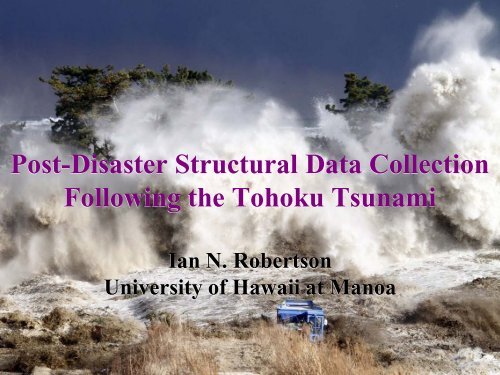
Post-Disaster Structural Data Collection<br />
Following the <strong>Tohoku</strong> <strong>Tsunami</strong><br />
Ian N. Robertson<br />
University of Hawaii at Manoa
Post-Disaster Structural Data Collection<br />
Following the <strong>Tohoku</strong> <strong>Tsunami</strong><br />
PI: Ian Robertson, University of Hawaii<br />
Collaborative PI: Michael Olsen, Oregon State Univ.<br />
The objective of this NSF-funded RAPID project was to<br />
perform detailed structural and LiDAR surveys of<br />
selected structures and surrounding topography for use<br />
in future time-history tsunami modeling of inundation and<br />
validation of non-linear structural response analysis.<br />
Major Outcomes<br />
1) Validation of NEOWAVE tsunami inundation modeling.<br />
2) Validation of hydrodynamic loading expressions<br />
developed in laboratory experiments.<br />
3) Contribution to development of tsunami design<br />
guidelines for use in future US design codes.
LiDAR Data Collection<br />
• 4 billion points collected for topography and structures<br />
• Topography maps of Sendai, Onagawa and Rikuzentakata<br />
• LiDAR scans of numerous structures available for detailed<br />
tsunami loading analysis<br />
Compiled 3-D LiDAR scan of Onagawa, Japan
NEOWAVE <strong>Tsunami</strong> Simulation<br />
• Kwok Fai Cheung and Yoshiki Yamazaki at UH<br />
• High resolution tsunami modeling from source to<br />
inundation<br />
• Shock capturing scheme to model wave breaking<br />
and bore formation<br />
• First Place at international competition at OSU
NEOWAVE Flow Depth - Onagawa
NEOWAVE Flow Velocity - Onagawa
Transect 2 N-S<br />
Transect 1 E-W
Transect 1 E-W<br />
— : MSL; — : sea level at tsunami arrival (-40cm)<br />
— : u; — : v; — : sqrt(u 2 +v 2 )<br />
x = 0m<br />
x = 100m<br />
x = 200m<br />
x = 300m<br />
x = 400m<br />
x = 500m<br />
x = 600m<br />
x = 700m<br />
x = 800m
Transect 2 N-S<br />
— : MSL; — : sea level at tsunami arrival (-40cm)<br />
— : u; — : v; — : sqrt(u 2 +v 2 )<br />
x = 0m<br />
x = 150m<br />
x = 300m<br />
x = 450m<br />
x = 600m<br />
x = 750m<br />
x = 900m<br />
x = 1050m<br />
x = 1200m<br />
x = 1350m
Case Studies for Evaluation of<br />
<strong>Tsunami</strong> Loads and Effects<br />
• Select structures or structural elements based on<br />
observed damage and likely cause<br />
• Determine estimates of flow depth and velocity<br />
• Complete structural failure only indicates that<br />
loads exceeded the capacity<br />
• Undamaged buildings show potential for<br />
success, but only indicate that capacity was<br />
greater than loads<br />
• Particularly interested in near-collapse or partial<br />
failure case studies
Lateral Loading on Walls - Japan<br />
• Onagawa reinforced concrete<br />
fish storage building<br />
• Hydrodynamic lateral load<br />
• Measure wall dimensions,<br />
reinforcement layout and take<br />
samples of rebar and concrete
Onagawa<br />
Outflow<br />
• Pressurized by flow stagnation.<br />
• Wall reinforcing tested to be JIS<br />
G3112 Grade SD 390.<br />
• The taller wall rupture occurred when<br />
the return flow ≥ 5.5 m/s.<br />
• Other shorter walls do not yield and<br />
so v < 7.5 m/s.<br />
• Video shows outflow between Marine<br />
Pal buildings at 7.5 to 8.5 m/s.<br />
Concrete<br />
Building<br />
5.5 < v < 7.5 m/s<br />
Steel<br />
Building<br />
Marine Pal<br />
Buildings<br />
7.5 < v < 8.5 m/s
Evaluation of Structural Response<br />
Steel-framed Building<br />
• Onagawa steel framed building near collapse<br />
• Measure all member sizes and overall dimensions<br />
• Note damage caused during drawdown – building<br />
leaning towards ocean
Onagawa Built Environment<br />
Captured with LiDAR<br />
• NSF Rapid grant - funding for<br />
LiDAR survey of selected<br />
buildings and topography<br />
• <strong>Survey</strong>s directed by Michael<br />
Olsen of OSU and Lyle Carden<br />
of Martin & Chock
Onagawa Three-Story Steel Building<br />
Frame Survival<br />
• Three-story steel moment-resisting<br />
frame exposed to 8 m/s outflow<br />
estimated from video analysis.<br />
• At about 67% blockage of the<br />
original enclosure (33% open), the<br />
return flow is sufficient to yield the<br />
top of the second story columns<br />
with 30-cm drift of third floor (First<br />
story column is stronger section.)<br />
• Fully clad building would have<br />
collapsed. Loss of cladding<br />
reduced the building’s projected<br />
area.<br />
• LiDAR scan shows final 50-cm<br />
third floor drift.
Sendai - Bore Strike on R/C Structure<br />
Minami Gamou STP Video<br />
Minami Gamou Wastewater Treatment Plant - subjected to direct bore impact
Bore Strike on R/C Structure<br />
Minami Gamou Wastewater Treatment Plant - subjected to direct bore impact<br />
Lidar Scan of deformed shape<br />
Structural drawings obtained from the<br />
Wastewater Treatment Plant<br />
Minami Gamou STP
Bore Strike on R/C Structure<br />
Interior view of 2-story wall<br />
Lidar scan of 2-story wall<br />
Minami Gamou Wastewater Treatment Plant
NEESR - Structural Loading<br />
Direct Bore Impact on Solid Wall<br />
Solitary Wave Breaking on Submerged Reef Crest
NEESR – Development of Performance<br />
Based <strong>Tsunami</strong> Engineering, PBTE
NEESR – Development of Performance<br />
Based <strong>Tsunami</strong> Engineering, PBTE
Hydrodynamic Force on Wall<br />
due to Bore Impact<br />
• Based on conservation of<br />
mass and momentum<br />
F<br />
w<br />
1 2<br />
⎛ 2<br />
4<br />
3<br />
3<br />
= ρ ⎜ + +<br />
1<br />
sw<br />
ghb<br />
h<br />
jv<br />
j<br />
g ( hjv<br />
j<br />
)<br />
⎝ 2<br />
⎞<br />
⎟<br />
⎠
Wall load expression<br />
comparison with experimental data
Velocity Analysis<br />
Video rate of 30 fps<br />
Time from Frame 260 to 316 = 1.87 sec.<br />
Distance between buildings = 12.2 m<br />
Bore velocity = 12.2/1.87 = 6.5 m/s<br />
Jump height approx. 5.5m over approx.<br />
0.5m standing water
Bore Impact Forces – Minami Gamou<br />
Wastewater Treatment Plant<br />
• Comparison with Different Bore Pressures<br />
used in Japan <strong>Tsunami</strong> Standards<br />
h j = 5.5m<br />
v j = 6.5m/s<br />
F<br />
w<br />
1 2<br />
⎛ 2<br />
4<br />
3<br />
3<br />
= ρ ⎜ + +<br />
1<br />
sw<br />
ghb<br />
hjv<br />
j<br />
g ( hjv<br />
j<br />
)<br />
⎝ 2<br />
⎞<br />
⎟<br />
⎠<br />
d s = 0.5m<br />
h b =h j +d s = 6.0m
Bore Impact Forces – Minami Gamou<br />
1600<br />
Wastewater Treatment Plant<br />
1400<br />
Maximum Force for 3x Hydrostatic Pressure<br />
Base Shear (kN) (per unit width of wall)<br />
1200<br />
1000<br />
800<br />
600<br />
400<br />
200<br />
First Yield at Edge of Wall<br />
First Yield of Ends of Roof Beams &<br />
First Yield at Midspan of Columns<br />
First Yield at Midheight of Wall<br />
First Yield of Beam at Ends of Wall &<br />
First Yield at Base of Wall<br />
First Yield of Columns at Base of Wall<br />
Maximum Force for OCADI Pressure<br />
Maximum Force for Theoretical Bore Pressure<br />
0<br />
0.00 0.10 0.20 0.30 0.40 0.50 0.60 0.70 0.80 0.90 1.00 1.10 1.20<br />
Maximum Transverse Wall Displacement (m)
FEA compared with Lidar scan<br />
(m) 0.0 0.10 0.20 0.30 0.40 0.50 0.60 0.70 0.80 0.90 1.0 1.10 1.20 1.30<br />
Minami Gamou Wastewater Treatment Plant - subjected to direct bore impact
ASCE 7-10<br />
Minimum Design Loads for Buildings and Other<br />
Structures<br />
Minimum Design Loads for Buildings and Other Structures<br />
• Chap 1 & 2 – General and load combinations<br />
• Chap 3 - Dead, soil and hydrostatic loads<br />
• Chap 4 - Live loads<br />
• Chap 5 - Flood loads (riverine and storm surge)<br />
• Chap 6 - Vacant<br />
• Chap 7 - Snow loads<br />
• Chap 8 - Rain loads<br />
• Chap 10 - Ice loads<br />
• Chap 11 – 23 - Seismic Design<br />
• Chap 26 – 31 - Wind Loads
Proposed ASCE 7-16<br />
Minimum Design Loads for Buildings and Other Structures<br />
• Chap 1 & 2 – General and load combinations<br />
• Chap 3 - Dead, soil and hydrostatic loads<br />
• Chap 4 - Live loads<br />
• Chap 5 - Flood loads (riverine and storm surge)<br />
• Chap 6 – <strong>Tsunami</strong> loads and effects<br />
• Chap 7 - Snow loads<br />
• Chap 8 - Rain loads<br />
• Chap 10 - Ice loads<br />
• Chap 11 – 23 - Seismic Design<br />
• Chap 26 – 31 - Wind Loads
ASCE 7 Sub-committee on<br />
<strong>Tsunami</strong> Loads and Effects<br />
• Formed in January 2011<br />
• 16 voting and 12 associate members<br />
• Chaired by Gary Chock, S.E., Martin & Chock Inc.<br />
• 3 meetings per year thus far with draft document now<br />
in development
Proposed Scope of the ASCE <strong>Tsunami</strong> Design Provisions<br />
2016 edition of the ASCE 7 Standard, Minimum Design Loads<br />
for Buildings and Other Structures<br />
6.1 General Requirements<br />
6.2 Definitions<br />
6.3 Symbols and Notation<br />
6.4 General <strong>Tsunami</strong> Design Criteria<br />
6.5 Procedures for <strong>Tsunami</strong> Hazard Assessment<br />
6.6 Procedures for <strong>Tsunami</strong> Inundation Analysis<br />
6.7 Design Parameters for <strong>Tsunami</strong> Flow over Land<br />
6.8 Design Procedure for <strong>Tsunami</strong> Inundation<br />
6.9 Hydrostatic Loads<br />
6.10 Hydrodynamic Loads<br />
6.11 Impact Loads<br />
6.12 Foundation Design<br />
6.13 Structural countermeasures for reduced loading on buildings<br />
6.14 Special Occupancy Structures<br />
6.15 Designated Nonstructural Systems (Stairs, Life Safety MEP)<br />
6.16 Non-building critical facility structures<br />
C6 Commentary and References
ASCE 7 Sub-committee on<br />
<strong>Tsunami</strong> Loads and Effects<br />
• Committee balloting scheduled for summer 2013, then<br />
transfer to ASCE 7 Main Committee<br />
• If adopted, will become Chapter 6 of ASCE 7-16<br />
• Will then be referenced by IBC 2018
Arigato Gosai Mas<br />
Any Questions?<br />
Tampered sign at Waikaloa Resort, Kona, Hawaii