Development of a Computer Program for Column ... - AU Journal
Development of a Computer Program for Column ... - AU Journal Development of a Computer Program for Column ... - AU Journal
AU J.T. 12(4): 289-295 (Apr. 2009) Development of a Computer Program for Column Analysis Alkali Babawuya Department of Mechanical Engineering, Federal University of Technology Minna, Nigeria E-mail: Abstract The conventional method of carrying out structural analysis of columns is tedious and time consuming, as it is characterized by sourcing for the design data and long processes of manipulation. This therefore necessitates the development of a computer program for structural analysis of columns. Visual Basic development tool was used in the program development. The fundamental principles of strength of materials were used in the program modeling. The program was designed to accept inputs through an assisting wizard. Sample problems were used to test the program and obtained results were analyzed. The obtained results were in agreement with the exact solutions. Keywords: Column analysis, buckling, slenderness ratio, Visual Basic. Introduction According to French (1995), columns are structural members that carry their loads axially rather than transversely. Columns may be: short and fat columns (Fig. 1), when loaded to such a point that the load actually crushes the materials; long and slender columns (Fig. 2) which are more likely to buckle under the higher axial loads; or beam columns (Fig. 3). Program Requirements (Hardware and Software) For a personal computer (PC) to run a computer program for structural analysis of columns, it is a matter of choice to have Windows operating system installed. Windows is a graphical user system and as such requires a substantial processor speed and memory to operate efficiently. A large hard disk is generally needed for Windows applications to facilitate easy access to needed and stored files. A VGA/SVGA screen display is required to enhance the quality of graphics output. The program could be developed using application/education-oriented programming languages such as Pascal (Holmes 2000) or Visual Basic (Microsoft Corporation 1997). A person with basic knowledge of engineering mechanics and basic window environment knowledge should conveniently use such program. Hopefully, the majority of users are familiar with windows, word processing and graphics packages (e.g., exploring windows using Windows Explorer, Paint Brush, etc.) and would be able to install and use the developed software with minimal efforts. Fig. 1. Short column with fixed ends. P Buckling length Fig. 2. Long slender column with pinned ends. P Displacement position Fig.3. Beam column. Technical Report 289
- Page 2 and 3: AU J.T. 12(4): 289-295 (Apr. 2009)
- Page 4 and 5: AU J.T. 12(4): 289-295 (Apr. 2009)
- Page 6 and 7: AU J.T. 12(4): 289-295 (Apr. 2009)
<strong>AU</strong> J.T. 12(4): 289-295 (Apr. 2009)<br />
<strong>Development</strong> <strong>of</strong> a <strong>Computer</strong> <strong>Program</strong> <strong>for</strong> <strong>Column</strong> Analysis<br />
Alkali Babawuya<br />
Department <strong>of</strong> Mechanical Engineering, Federal University <strong>of</strong> Technology<br />
Minna, Nigeria<br />
E-mail: <br />
Abstract<br />
The conventional method <strong>of</strong> carrying out structural analysis <strong>of</strong> columns is tedious<br />
and time consuming, as it is characterized by sourcing <strong>for</strong> the design data and long<br />
processes <strong>of</strong> manipulation. This there<strong>for</strong>e necessitates the development <strong>of</strong> a computer<br />
program <strong>for</strong> structural analysis <strong>of</strong> columns. Visual Basic development tool was used in<br />
the program development. The fundamental principles <strong>of</strong> strength <strong>of</strong> materials were<br />
used in the program modeling. The program was designed to accept inputs through an<br />
assisting wizard. Sample problems were used to test the program and obtained results<br />
were analyzed. The obtained results were in agreement with the exact solutions.<br />
Keywords: <strong>Column</strong> analysis, buckling, slenderness ratio, Visual Basic.<br />
Introduction<br />
According to French (1995), columns are<br />
structural members that carry their loads<br />
axially rather than transversely. <strong>Column</strong>s may<br />
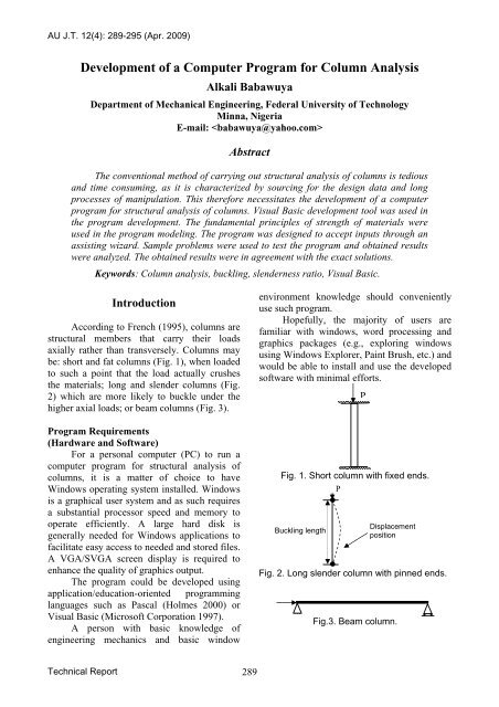
be: short and fat columns (Fig. 1), when loaded<br />
to such a point that the load actually crushes<br />
the materials; long and slender columns (Fig.<br />
2) which are more likely to buckle under the<br />
higher axial loads; or beam columns (Fig. 3).<br />
<strong>Program</strong> Requirements<br />
(Hardware and S<strong>of</strong>tware)<br />
For a personal computer (PC) to run a<br />
computer program <strong>for</strong> structural analysis <strong>of</strong><br />
columns, it is a matter <strong>of</strong> choice to have<br />
Windows operating system installed. Windows<br />
is a graphical user system and as such requires<br />
a substantial processor speed and memory to<br />
operate efficiently. A large hard disk is<br />
generally needed <strong>for</strong> Windows applications to<br />
facilitate easy access to needed and stored files.<br />
A VGA/SVGA screen display is required to<br />
enhance the quality <strong>of</strong> graphics output.<br />
The program could be developed using<br />
application/education-oriented programming<br />
languages such as Pascal (Holmes 2000) or<br />
Visual Basic (Micros<strong>of</strong>t Corporation 1997).<br />
A person with basic knowledge <strong>of</strong><br />
engineering mechanics and basic window<br />
environment knowledge should conveniently<br />
use such program.<br />
Hopefully, the majority <strong>of</strong> users are<br />
familiar with windows, word processing and<br />
graphics packages (e.g., exploring windows<br />
using Windows Explorer, Paint Brush, etc.) and<br />
would be able to install and use the developed<br />
s<strong>of</strong>tware with minimal ef<strong>for</strong>ts.<br />
Fig. 1. Short column with fixed ends.<br />
P<br />
Buckling length<br />
Fig. 2. Long slender column with pinned ends.<br />
P<br />
Displacement<br />
position<br />
Fig.3. Beam column.<br />
Technical Report 289
<strong>AU</strong> J.T. 12(4): 289-295 (Apr. 2009)<br />
Need <strong>for</strong> the <strong>Program</strong><br />
The need <strong>for</strong> a computer s<strong>of</strong>tware to<br />
assist in solving mechanics problems is<br />
obvious <strong>for</strong> the fact that engineering mechanics<br />
problems require long computations and<br />
graphical results. These processes are<br />
complicated and time consuming. With the<br />
attainment <strong>of</strong> the computer age, there is need<br />
<strong>for</strong> replacement <strong>of</strong> traditional way <strong>of</strong> solving<br />
engineering problems in a computerized (i.e.,<br />
more modern) way, so as to reap the benefits<br />
accrued in the use <strong>of</strong> computers (such as time<br />
saving, accuracy, versatility, efficiency and<br />
reliability).<br />
One <strong>of</strong> the problems <strong>of</strong> the traditional<br />
problem solving process is the long and<br />
complex manipulation process, which is easily<br />
and accurately handled by computers.<br />
Theoretical Analysis<br />
The analysis presented here will be based<br />
on SI units, but the program will be designed to<br />
accept and convert other standard units <strong>of</strong><br />
measurement.<br />
The analyses presented here are on long<br />
slender column with the following end<br />
conditions:<br />
- Clamped-free columns;<br />
- Clamped-pinned columns;<br />
- Clamped-clamped column;<br />
- Pin ended column;<br />
- Pin ended beam-column;<br />
- Eccentrically loaded columns;<br />
- Cantilever columns.<br />
<strong>Column</strong> Buckling Loads<br />
According to Shames (1996), a column<br />
carrying an increasing load will reach a time in<br />
which the deflection can be considered to be<br />
large. At that time the load can be considered<br />
critical, i.e., the load which causes the column<br />
to attain a condition <strong>of</strong> neutral equilibrium. The<br />
critical load <strong>of</strong> a column depends on the end<br />
condition. Euler’s equation (Eq. 1) is used to<br />
establish some critical loads shown in Table 1:<br />
d 2 M/dx 2 + M/EI = 0, (1)<br />
where: M = moment variable <strong>of</strong> the column; I =<br />
moment <strong>of</strong> inertia <strong>of</strong> beam; and E = Young<br />
modulus <strong>of</strong> elasticity.<br />
Table 1. Showing column end conditions and<br />
<strong>for</strong>mulas.<br />
S/no <strong>Column</strong> end<br />
Critical load<br />
condition<br />
1 Clamped-Free = π 2 E I / 4 L 2<br />
2 Clamped – Pinned = 2.05π 2 E I / L 2<br />
3 Clamped – Clamped = 4π 2 E I / L 2<br />
4 Pinned ended = π 2 E I / L 2<br />
Design Factors<br />
The design <strong>of</strong> a column requires the<br />
determination <strong>of</strong> the maximum axial load<br />
allowable. This depends on the column<br />
material and the slenderness ratio <strong>of</strong> the<br />
column. Majorities <strong>of</strong> columns are designed by<br />
reference to tables <strong>of</strong> permissible stress<br />
standards available in engineering design<br />
manuals. The critical load <strong>for</strong> a column<br />
depends on its cross-sectional dimensions.<br />
Slenderness Ratio<br />
The slenderness ratio involves not only<br />
height or length <strong>of</strong> the column, but also the size<br />
and shape <strong>of</strong> its cross-section and the end<br />
conditions.<br />
The slenderness ratio <strong>of</strong> a column is the<br />
ratio <strong>of</strong> the effective length <strong>of</strong> the column to<br />
the least width <strong>of</strong> the column.<br />
S<strong>of</strong>tware <strong>Development</strong> and<br />
Environments<br />
S<strong>of</strong>tware is what breath life into the<br />
computer. It make each hardware to function<br />
well and also allow a specific application <strong>of</strong><br />
computer possible. Without good and efficient<br />
s<strong>of</strong>tware a computer will be good <strong>for</strong> nothing.<br />
S<strong>of</strong>tware <strong>Development</strong> Steps<br />
S<strong>of</strong>tware development process entails<br />
converting broad system specification into<br />
usable machine instructions that produce<br />
desired results. It is a challenging process that<br />
does not begin and end with the writing and/or<br />
keying <strong>of</strong> lines <strong>of</strong> code. A program designer<br />
must follow a series <strong>of</strong> steps be<strong>for</strong>e they can<br />
Technical Report 290
<strong>AU</strong> J.T. 12(4): 289-295 (Apr. 2009)<br />
use computers to per<strong>for</strong>m useful work. These<br />
steps are (French 1996; Rilwan 2004):<br />
Defining The Need<br />
The particular problem to be solved, or the<br />
tasks to be accomplished must be clearly<br />
defined (<strong>for</strong> example “<strong>Computer</strong> Aided<br />
Structural Analysis)”. In an ideal situation,<br />
the users <strong>of</strong> the program a pr<strong>of</strong>essional in<br />
that field and data processing specialist<br />
work together in defining the need.<br />
System Analysis<br />
At this stage, data pertaining to the problem<br />
is gathered with data acquisition and<br />
analyzed.<br />
System Design<br />
A system (i.e., programming sequence)<br />
required to achieve the need through the<br />
data gathered and analyzed is designed. The<br />
design specification include desired output,<br />
input, and the general processing<br />
procedures, computation, logical structure,<br />
simple sequence structures, selector<br />
structures, loop structures, branch<br />
structures, etc.<br />
<strong>Program</strong>ming Analysis<br />
The system specification is further broken<br />
down into the input/output (I/O),<br />
calculations, logical/comparison and<br />
storage/retrieval operations required to<br />
satisfy the need. Also, at this stage the<br />
desired eutectic designs are conceived, such<br />
as <strong>for</strong>m, size and colors, control<br />
arrangement <strong>of</strong> controls on <strong>for</strong>ms, etc.<br />
<strong>Program</strong> Preparation<br />
The mathematical modeling (i.e., analysis)<br />
in is translated and coded in a <strong>for</strong>m<br />
acceptable to the compiler (i.e., high level<br />
language). This stage involves testing a<br />
translated code by interpreter and each<br />
module by a compiler to see that all<br />
modules per<strong>for</strong>m their various functions.<br />
Testing And Implementation<br />
The coded program is checked <strong>for</strong> errors<br />
(e.g., syntax and logical errors) by testing<br />
each module and the overall program prior<br />
to being compiled and made into a<br />
executable file <strong>for</strong> use on a routine basis.<br />
During the testing process, sample data are<br />
entered and the output results are compared<br />
with other sources.<br />
<strong>Program</strong> Maintenance<br />
Maintenance modules <strong>for</strong> future<br />
modifications and improvements are<br />
provided. Also, a help module is being<br />
provided containing basic guidelines.<br />
Structure <strong>of</strong> the <strong>Program</strong><br />
MDI Form<br />
The program was designed on one Multi<br />
Document Interface (MDI) <strong>for</strong>m (Micros<strong>of</strong>t<br />
Corporation 1997), with two MDI child <strong>for</strong>ms<br />
interrelated <strong>for</strong> easy data transfer and efficient<br />
setup. The MDI <strong>for</strong>m contains some controls<br />
fashioned to ease the problem definition. It<br />
contains controls like picture box, labels,<br />
frames, command buttons, textboxes, option<br />
button, and menu (Fig. 4).<br />
Form 1 (Output Screen)<br />
This is an MDI child with control<br />
buttons. On this <strong>for</strong>m, column design<br />
parameters are obtained based on the design<br />
intended on the screen (Fig. 5).<br />
<strong>Program</strong> Flowchart<br />
The flow sequence <strong>of</strong> the program is<br />
shown in Fig. 6 starting from selecting the type<br />
<strong>of</strong> the column down to the output results.<br />
Installing, Testing and Discussion <strong>of</strong><br />
Results<br />
<strong>Program</strong> Installation<br />
The s<strong>of</strong>tware was compiled and burned<br />
onto compact disks (CD plates).<br />
To successfully install the s<strong>of</strong>tware, the<br />
completion <strong>of</strong> the following steps is necessary:<br />
- Insert the CD plate containing the<br />
installer into the CD-ROM drive.<br />
- If it does not auto run, open the file<br />
sleandercollumn.exe from the CD-<br />
ROM.<br />
- Follow the installation wizard screens<br />
and read carefully the instructions to the<br />
end.<br />
Technical Report 291
<strong>AU</strong> J.T. 12(4): 289-295 (Apr. 2009)<br />
Fig. 4. Main screen.<br />
Fig. 5. Output screen.<br />
Technical Report 292
<strong>AU</strong> J.T. 12(4): 289-295 (Apr. 2009)<br />
Start<br />
Select analysis types<br />
Input design parameters, e.g., L, P, I,<br />
etc.<br />
Output: P crit , I, A, etc.<br />
If the analysis<br />
is complete<br />
No<br />
Yes<br />
Analysis <strong>of</strong><br />
same column<br />
Yes<br />
No<br />
Stop<br />
Fig. 6. A flow chart <strong>of</strong> the computer program.<br />
<strong>Program</strong> Testing.<br />
The compiled and installed program was<br />
tested with several sample data sets obtained<br />
from mechanics textbooks (Khurmi 2000;<br />
Durka et al. 1996; Ryder 1969; Seward 1998).<br />
The testing was done in order to compare<br />
the program output with conventional results<br />
found in textbooks. If the computational results<br />
coincide with known numerical results in a<br />
number <strong>of</strong> selected clear-cut private cases <strong>for</strong><br />
which exact analytical solutions are known,<br />
this is an indication that the program would<br />
provide reliable data <strong>for</strong> arbitrary scenarios.<br />
Results and Discussion<br />
Various input data were fed into the<br />
program and the obtained computational results<br />
<strong>of</strong> the tests are identical with the results from<br />
the sources, the small differences occur as a<br />
result <strong>of</strong> round-<strong>of</strong>f error. And due to such<br />
negligible discrepancies, it can be estimated<br />
that the program would function properly with<br />
arbitrary input data.<br />
As an illustration, the data used to test the<br />
program (column with both ends pinned) result<br />
in a solution (Fig. 7) which is equivalent to the<br />
one (Fig. 8) given also by Seward (1998).<br />
Technical Report 293
<strong>AU</strong> J.T. 12(4): 289-295 (Apr. 2009)<br />
Fig. 7. Sample problem and solution <strong>for</strong> a column with both ends pinned.<br />
Example 8.2<br />
Determine the critical Euler buckling load <strong>of</strong> a<br />
solid aluminium rod <strong>of</strong> diameter 12 mm if it<br />
has a length <strong>of</strong> 1.0 m between pin-ended<br />
supports.<br />
Solution<br />
2<br />
π EI<br />
From [8.9] P crit =<br />
2<br />
L<br />
From table 3.4 E = 70 000 N/mm 2<br />
From figure 7.31 I = πr 4 /4 = π x 6 4 /4 = 1018<br />
mm 4<br />
2<br />
π × 70000 ×1018<br />
There<strong>for</strong>e P crit = = 703 N<br />
2<br />
1000<br />
Answer Critical Euler buckling load =<br />
0.703 kN<br />
Fig. 8. Sample problem and solution. Source:<br />
Seward (1998).<br />
Summary, Conclusion and<br />
Recommendations<br />
Summary<br />
A program <strong>for</strong> structural analysis <strong>of</strong><br />
columns was successfully developed. The<br />
programming development process does not<br />
just involve analysis and coding <strong>of</strong> programs,<br />
but also requires tedious piping and debugging<br />
process, followed by program compilation.<br />
The most difficult problem encountered<br />
in this work was at the modeling stage (that is,<br />
trying to adopt standards <strong>of</strong> analysis from<br />
various sources).<br />
Conclusion<br />
In the face <strong>of</strong> numerous constraints, this<br />
work was brought to a practical level, i.e., an<br />
operational computer program <strong>for</strong> column<br />
analysis was developed based on fundamental<br />
concepts <strong>of</strong> structural mechanics.<br />
The executable program<br />
(SLENDERCOLLUMN.EXE) is 324KB in<br />
size, while the compiled program ready <strong>for</strong><br />
installation is comprised <strong>of</strong> cabinet files, two<br />
setup files and a text file (i.e.,<br />
SLENDERCOLLUMN.CAB, SC1.CAB,<br />
SC2.CAB, SC3.CAB, SETUP.1ST,<br />
SETUP.EXE and README.TXT), all<br />
amounting to 15.8MB in size. It will take<br />
maximum <strong>of</strong> a few minutes per problem to<br />
obtain results when using the program.<br />
This s<strong>of</strong>tware is in close con<strong>for</strong>mity to<br />
other existing application programs, and is<br />
fashioned to simplify most aspects <strong>of</strong> structural<br />
mechanics discussed earlier. It is hoped to be <strong>of</strong><br />
some help to engineering pr<strong>of</strong>essionals.<br />
Technical Report 294
<strong>AU</strong> J.T. 12(4): 289-295 (Apr. 2009)<br />
Recommendations<br />
The room <strong>for</strong> further improvements in<br />
this program could be in the following areas:<br />
- Interfacing with other graphics<br />
s<strong>of</strong>tware;<br />
- Accommodating more types <strong>of</strong> column<br />
problems;<br />
- Statically indeterminate problems<br />
should be accommodated.<br />
References<br />
French, C.S. 1996. Oliver and Chapman’s data<br />
processing and in<strong>for</strong>mation technology.<br />
Thomson Learning, London, UK, pp. 300-<br />
93.<br />
French, S.E. 1995. Fundamentals <strong>of</strong> structural<br />
analysis. West Publishing Company,<br />
Minneapolis, MN, USA.<br />
Holmes, B.J. 2000. Pascal programming.<br />
Thomson Learning, London, UK.<br />
Khurmi, R.S. 2000. Textbook <strong>of</strong> structural<br />
mechanics. S. Chand & Co., Ltd., New<br />
Delhi, India.<br />
Micros<strong>of</strong>t Corporation (Ed.). 1997. Micros<strong>of</strong>t<br />
Visual Basic 5.0 programmer’s guide.<br />
Micros<strong>of</strong>t Press, Bellevue, WA, USA.<br />
Durka, M.F.; Morgan, W.; and Williams, D.T.<br />
1996. Structural mechanics. 5 th ed. Addison<br />
Wesley Longman, Harlow, Essex, UK.<br />
Rilwan, U. 2004. A s<strong>of</strong>tware <strong>of</strong> high curves<br />
design. Post Graduate Diploma (PGD)<br />
Project, Civil Engineering Department,<br />
Bayero University <strong>of</strong> Kano, Kano State,<br />
Nigeria, pp. 30-42.<br />
Ryder, G.H. 1969. Strength <strong>of</strong> materials. 3 rd ed.<br />
English Language Book Society (ELBS)<br />
and Macmillan, London, UK, pp. 238-47.<br />
Seward, D. 1998. Understanding structures –<br />
analysis, materials, design. Macmillan,<br />
Basingstoke, Hampshire, UK.<br />
Shames, H.I. 1996. Engineering mechanics –<br />
statics and dynamics. 4 th ed. Prentice Hall,<br />
New Delhi, India.<br />
Technical Report 295


