Simulation of Fatigue Crack Growth of Locally ... - AU Journal
Simulation of Fatigue Crack Growth of Locally ... - AU Journal
Simulation of Fatigue Crack Growth of Locally ... - AU Journal

Create successful ePaper yourself
Turn your PDF publications into a flip-book with our unique Google optimized e-Paper software.
<strong>AU</strong> J.T. 11(3): 195-197 (Jan. 2008)<br />
<strong>Simulation</strong> <strong>of</strong> <strong>Fatigue</strong> <strong>Crack</strong> <strong>Growth</strong><br />
<strong>of</strong> <strong>Locally</strong> Machined Bolts in Nigeria<br />
Ogwuagwu Obiajulu Vincent<br />
Department <strong>of</strong> Mechanical Engineering, Federal University <strong>of</strong> Technology<br />
Minna, Niger State, Nigeria<br />
<br />
Abstract<br />
A simulation study <strong>of</strong> the fatigue fracture and failure characteristics <strong>of</strong> locally<br />
machined bolts is presented. The numerical results obtained show that the bolts have<br />
low stress intensity factor as well as load cycles before failure. Recommendation was<br />
made on how to improve on these properties.<br />
Keywords: <strong>Fatigue</strong> fracture, stress intensity factor, threshold stress intensity factor.<br />
Introduction<br />
The evolution <strong>of</strong> small-scale enterprises<br />
in the country has led to the setting up <strong>of</strong> many<br />
small machine shops involved in the<br />
production <strong>of</strong> bolts and nuts, as well as power<br />
screws. These bolts and nuts are usually<br />
machined from carbon steel bar stocks and are<br />
never treated after machining. Also, because<br />
there are no quality control measures involved<br />
in the production process, some <strong>of</strong> these bolts<br />
get into the market with surface cracks at the<br />
root <strong>of</strong> the threads.<br />
The use <strong>of</strong> these bolts always lead to<br />
premature failure even when the machine is not<br />
operation, ie. During the assembling process <strong>of</strong><br />
the machine parts. This has necessitated the<br />
simulation <strong>of</strong> the fatigue crack growth and<br />
fracture failure characteristics <strong>of</strong> such bolts.<br />
There are analytical and semi analytical<br />
methods for fracture analysis such as those<br />
used by Delale and Erdogan (1983), Erdogan<br />
(1995), Chan et al. (2001) and Erdogan and<br />
Wu (1997) in their studies. The problem <strong>of</strong><br />
fracture can also be associated with grain size,<br />
shape as well as grain boundaries orientations<br />
(Evans and Feler). Since the machined bolts are<br />
not treated after machining, the role <strong>of</strong> material<br />
characteristics in fracture failure <strong>of</strong> these bolts<br />
is also a major factor.<br />
Problem Formulation<br />
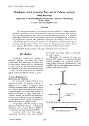
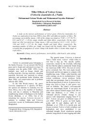
Fig. 1 shows the model <strong>of</strong> a bolt under<br />
load. Using the linear fracture mechanics, the<br />
direction criteria may be dependent upon the<br />
fracture criterion (Erdogan and Sih 1963).<br />
However, in the case <strong>of</strong> elastic-plastic fracture<br />
mechanics, the direction criterion likely to be<br />
dependent on upon the state <strong>of</strong> stress or strain<br />
at the crack tip.<br />
Fig. 1. Model <strong>of</strong> a bolt under load<br />
In polar coordinates, the stress or strain in<br />
a linear elastic cracked body may be<br />
represented as<br />
y<br />
σ y<br />
r<br />
τ xy<br />
σ x<br />
θ<br />
x<br />
195
<strong>AU</strong> J.T. 11(3): 195-197 (Jan. 2008)<br />
n<br />
⎛ k ⎞ ∞<br />
σ = ⎜ ⎟f<br />
() θ A r 2 c<br />
n<br />
ij<br />
+<br />
n ij<br />
() θ (1)<br />
ij<br />
∑<br />
⎝ r ⎠ n = 0<br />
Where σ ij is the stress tensor and r and θ<br />
defines a given point in the body in polar<br />
coordinates in relation to the crack and k is a<br />
constant (stress intensity factor) Both f ij and c ij<br />
are all functions <strong>of</strong> θ. For mode I crack<br />
equation (1) reduces to the form<br />
k<br />
I<br />
σ<br />
ij<br />
=<br />
(2)<br />
2π r<br />
The following stress and displacement<br />
fields are obtained for n ≤ 2<br />
k<br />
k<br />
I<br />
θ⎛ θ 3θ ⎞<br />
I<br />
θ⎛ θ 3θ ⎞<br />
σxx<br />
= cos ⎜1<br />
− sin sin ⎟ = sin ⎜2<br />
+ cos cos ⎟(3)<br />
2πr 2⎝<br />
2 2⎠ 2πr 2⎝<br />
2 2 ⎠<br />
k θ θ 3θ k<br />
I ⎛ ⎞<br />
I<br />
θ θ 3θ<br />
σyy<br />
= cos ⎜1<br />
+ sin sin ⎟+<br />
cos sin<br />
cos (4)<br />
2πr 2⎝<br />
2 2⎠<br />
2πr 2 2 2<br />
k θ θ 3θ k<br />
I<br />
I<br />
θ⎛ θ 3θ ⎞<br />
τxy<br />
= cos sin cos<br />
+ cos<br />
⎜1<br />
− sin<br />
sin<br />
⎟ (5)<br />
2πr 2 2 2 2πr 2⎝<br />
2 2⎠<br />
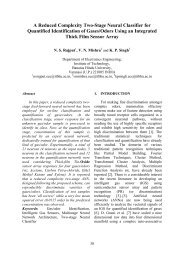
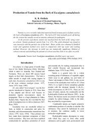
<strong>Crack</strong> size (mm)<br />
stress intensity factor Δk th and the stress<br />
intensity factor Δk with number <strong>of</strong> cycles <strong>of</strong><br />
loading.<br />
Fig. 2. Variation <strong>of</strong> crack size c with loading cycles<br />
Also,<br />
σ zz = 0 for plain stress and<br />
σ zz = υ(σ xx + σ yy ) for plain strain.<br />
Equations (3) through (5) above are <strong>of</strong> O(r ½ )<br />
accuracy..<br />
For solid circular sections the relation<br />
for the crack size c is given by<br />
− ⎡a<br />
( 2r<br />
− a)<br />
⎤<br />
c = r tan 1<br />
⎢<br />
(6)<br />
2r<br />
( r a)<br />
⎥<br />
⎣ − ⎦<br />
c<br />
θ =<br />
(7)<br />
r<br />
Where c is crack length in the peripheral<br />
direction.<br />
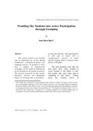
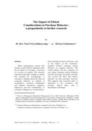
Δkmax MPamm ½<br />
Fig. 3. Variation <strong>of</strong> stress intensity factor ΔK max<br />
with number <strong>of</strong> cycles N<br />
Results and Discussion<br />
In the numerical simulation, properties <strong>of</strong><br />
low carbon steel were used since these bolts are<br />
usually machined from these steels.<br />
Fig. 2 shows the variation <strong>of</strong> crack size c<br />
with number <strong>of</strong> loading cycles while Fig. 3<br />
show the variation <strong>of</strong> stress intensity factor k<br />
with number <strong>of</strong> loading cycles. Fig. 4 through 6<br />
shows the crack growth rate, c, threshold stress<br />
intensity factor, Δk th and ratio <strong>of</strong> the threshold<br />
196<br />
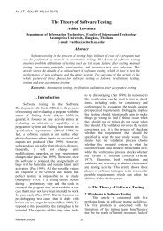
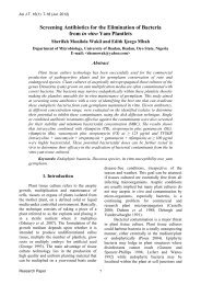
da/dN (mm/cycle)<br />
Fig. 4. <strong>Crack</strong> growth rate c, with number <strong>of</strong><br />
cycles N
<strong>AU</strong> J.T. 11(3): 195-197 (Jan. 2008)<br />
Δk MPamm ½<br />
From Fig. 4, the rate <strong>of</strong> change <strong>of</strong> crack<br />
size, c is zero even before the bolt attained<br />
20,000 cycles <strong>of</strong> loading. At this point, the rate<br />
<strong>of</strong> growth <strong>of</strong> the crack size c is about 4.505x10- 7 .<br />
The threshold stress intensity factor Δk th<br />
as shown in Fig. 5. is 256.5 MPa mm ½ .<br />
The variation <strong>of</strong> ration <strong>of</strong> the stress<br />
intensity factor to the threshold stress intensity<br />
factor as shown in Fig. 6 is smooth at the early<br />
stage. However, the slope <strong>of</strong> the curve changed<br />
after about 13,300 cycles <strong>of</strong> loading.<br />
Conclusion<br />
ΔKth / Δk<br />
Fig. 5. Variation <strong>of</strong> Threshold stress intensity<br />
factor Δk<br />
Fig. 6. Variation <strong>of</strong> ration the threshold stress<br />
intensity, Δk th factor to stress intensity<br />
factor Δk<br />
From Fig. 2, the crack size, c stabilized<br />
after about 20,000 cycles <strong>of</strong> loading. Fig. 3<br />
shows that the bolts have very low stress<br />
intensity factor, Δk <strong>of</strong> about 43.52MPa mm ½ .<br />
This explains the high rate <strong>of</strong> bolt failure being<br />
experienced while in use. This phenomenon is<br />
attributable to the lack <strong>of</strong> treatment <strong>of</strong> the bolts<br />
after machining.<br />
The behavior <strong>of</strong> the bolt is largely<br />
attributable to the non treatment <strong>of</strong> these bolts<br />
after machining. The ratio <strong>of</strong> growth increment<br />
on current crack size, c is about 0.005. At abbot<br />
13,300 cycles <strong>of</strong> loading most <strong>of</strong> the bolt<br />
failure characteristics have changed remarkably,<br />
although at this stage, the critical crack<br />
size has not been attained.<br />
References<br />
Chan, Y.S., Paulino, G.H. and Fannjiang, A.C.<br />
2001. The crack problem for a nonhomogeneous<br />
material under antiplane<br />
shear loading – A displacement based<br />
formulation. Int. J. Solid Struct. 38: 2989-<br />
3005.<br />
Delale, F.; and Erdogan, F. 1983. The crack<br />
problem for a non-homogeneous phase. J.<br />
Appl. Mechan. (ASME) 50: 609-14.<br />
Erdogan, F. 1995. Fracture mechanics <strong>of</strong><br />
functionally graded materials. J. Composite<br />
Engin. 5: 753-70.<br />
Erdogan, F.; and Sih, G.C. 1963 On the crack<br />
extension in plates under plane loading and<br />
transverse shear. J. Basic Engin. Vol. 2:<br />
519-27.<br />
Erdogan, F.; and Wu, B.H. 1997. The surface<br />
crack problem for a plat with functionally<br />
graded properties. J. Appl. Mechan.<br />
(ASME) 50: 449-56.<br />
197