Design Analysis of an Electric Induction Furnace for ... - AU Journal
Design Analysis of an Electric Induction Furnace for ... - AU Journal
Design Analysis of an Electric Induction Furnace for ... - AU Journal

Create successful ePaper yourself
Turn your PDF publications into a flip-book with our unique Google optimized e-Paper software.
<strong>AU</strong> J.T. 9(2): 83-88 (Oct. 2005)<br />
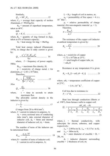
Similarly,<br />
Qsh = MC m<br />
θ<br />
sh<br />
.................................12<br />
where, C m = average heat capacity <strong>of</strong> molten<br />
Aluminum, (= 992J/kg K);<br />
θ sh = amount <strong>of</strong> superheat temperature,<br />
taken as 40°C.<br />
<strong>an</strong>d,<br />
Q<br />
s<br />
= K<br />
sGs<br />
.......................................13<br />
where, K s = qu<strong>an</strong>tity <strong>of</strong> slag <strong>for</strong>med in (kg),<br />
taken as 8% <strong>of</strong> furnace capacity;<br />
G s = heat energy <strong>for</strong> slag = 18kJ/kg.<br />
Total heat energy induced (Hammond,<br />
1978), in charge due to eddy current is given<br />
by:<br />
3 2 2 4<br />
π f H<br />
mBmaxdm<br />
Q<br />
ec<br />
=<br />
.................. 14<br />
8ρ<br />
where, f = frequency <strong>of</strong> power supply,<br />
50Hz;<br />
B max = maximum flux density, H;<br />
ρ = resistivity <strong>of</strong> charge metal, ( <strong>for</strong><br />
aluminum, ρ = 2.83 x 10 -8 Ωm).<br />
There<strong>for</strong>e,<br />
8ρQec<br />
Bmax<br />
=<br />
....................15<br />
3 2 4<br />
π f d<br />
m<br />
H<br />
m<br />
Also<br />
Qth<br />
Qec = ........................................ 16<br />
t<br />
where, t = time in seconds to attain<br />
maximum flux.<br />
The allowable current density in the<br />
inductor is given by:<br />
I<br />
J = ............................................... 17<br />
A t<br />
(J r<strong>an</strong>ges from 20 to 40A/mm 2 ).<br />
where, I = current in inductor in amperes, A;<br />
A t = cross sectional area <strong>of</strong> conducting<br />
tube (mm 2 ), take external diameter <strong>of</strong><br />
inductor coil, d t2 = 8mm <strong>an</strong>d internal<br />
diameter <strong>of</strong> inductor coil, d t1 = 6mm.<br />
The number <strong>of</strong> turns <strong>of</strong> the inductor c<strong>an</strong><br />
be determined from:<br />
μ NI<br />
B<br />
r<br />
μ<br />
max<br />
= o<br />
.....................................<br />
L<br />
where, N = number <strong>of</strong> turns <strong>of</strong> inductor coil;<br />
I = current in coil in amperes, A;<br />
18<br />
L = H in = length <strong>of</strong> coil in metres, m;<br />
μ o = permeability <strong>of</strong> free space = 4 π x<br />
10 -7 Hm -1 ;<br />
μ r = relative permeability <strong>of</strong> charge<br />
material, (<strong>for</strong> non-magnetic material μ r = 1).<br />
There<strong>for</strong>e,<br />
Bmax<br />
L<br />
N = ........................................... 19<br />
I<br />
μ o<br />
The resist<strong>an</strong>ce <strong>of</strong> the copper coil inductor<br />
at ambient temperature is given by:<br />
ρ<br />
cl<br />
Rθ o<br />
= .......................................... 20<br />
A<br />
t<br />
where, ρ c = resistivity <strong>of</strong> copper<br />
=1.72 x 10 -8 Ωm at 25°C;<br />
l = total length <strong>of</strong> copper tube, m;<br />
= πD in N<br />
as:<br />
Resist<strong>an</strong>ce at <strong>an</strong>y temperature θ is given<br />
R<br />
θ<br />
= R<br />
1 + αθ ( θ − θ )]<br />
θ<br />
[<br />
o<br />
o o<br />
.................. 21<br />
where, αθ o = temperature coefficient <strong>of</strong> copper<br />
at 25°C;<br />
= 3.9 x 10 -3 K -1 .<br />
Coil loss due to resist<strong>an</strong>ce is:<br />
2<br />
P c<br />
= I ...........................................22<br />
R θ<br />
Heat loss through conduction (Shrets et<br />
al. 1987), from furnace walls to copper coil:<br />
πH<br />
m<br />
( θ<br />
2<br />
− θ )<br />
QL<br />
=<br />
1 1 d<br />
2 1 Din<br />
1 d3<br />
[ ln + ln + ln ]<br />
2 λzi<br />
Dc<br />
λas<br />
d<br />
2<br />
λcu<br />
Din<br />
....................................... 23<br />
where, λ = thermal conductivity, with<br />
subscripts <strong>for</strong> zircon, asbestos, <strong>an</strong>d copper<br />
respectively;<br />
λ zi = 2.093w/m K; λ as = 0.117w/ m K;<br />
<strong>an</strong>d λ cu = 380w/m K;<br />
d 2 = outer diameter <strong>of</strong> crucible = D c +<br />
2B r , m;<br />
d 3 = inductor diameter surrounding<br />
crucible + 2 thickness <strong>of</strong> coil, m;<br />
86