

Users Manual WP 900 UHF.pdf - Jotron
Users Manual WP 900 UHF.pdf - Jotron
Users Manual WP 900 UHF.pdf - Jotron

Create successful ePaper yourself
Turn your PDF publications into a flip-book with our unique Google optimized e-Paper software.
Installation Guide<br />
Alarm Module T941AM8<br />
TD 90858GB<br />
Handook page<br />
47/128<br />
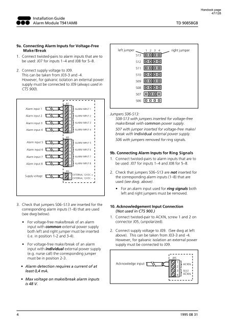
9a. Connecting Alarm Inputs for Voltage-Free<br />
Make/Break<br />
left jumper<br />
1<br />
2 3 4<br />
right jumper<br />
1. Connect twisted-pairs to alarm inputs that are to<br />
be used: J07 for inputs 1–4 and J08 for 5–8.<br />
S13<br />
S12<br />
2. Connect supply voltage to J09.<br />
This can be taken from J03-3 and -4.<br />
However, for galvanic isolation an external power<br />
supply must be connected to J09 (always used in<br />
CTS <strong>900</strong>).<br />
S11<br />
S10<br />
S09<br />
S08<br />
S07<br />
Alarm input 1<br />
Alarm input 2<br />
Alarm input 3<br />
Alarm input 4<br />
Alarm input 5<br />
Alarm input 6<br />
Alarm input 7<br />
Alarm input 8<br />
J07<br />
1<br />
2<br />
3<br />
4<br />
5<br />
6<br />
7<br />
8<br />
J08<br />
1<br />
2<br />
3<br />
4<br />
5<br />
6<br />
7<br />
8<br />
ALARM INPUT 1<br />
ALARM INPUT 2<br />
ALARM INPUT 3<br />
ALARM INPUT 4<br />
ALARM INPUT 5<br />
ALARM INPUT 6<br />
ALARM INPUT 7<br />
ALARM INPUT 8<br />
S06<br />
Jumpers S06-S13:<br />
S08-S13 with jumpers inserted for voltage-free<br />
make/break with common power supply.<br />
S07 with jumper inserted for voltage-free make/<br />
break with individual external power supply.<br />
S06 with jumpers removed for ring signals.<br />
9b. Connecting Alarm Inputs for Ring Signals<br />
1. Connect twisted-pairs to alarm inputs that are to<br />
be used: J07 for inputs 1–4 and J08 for 5–8.<br />
Supply voltage<br />
J09<br />
1 EXTERNAL 12VDC +<br />
2 EXTERNAL 12VDC –<br />
2. Check that jumpers S06–S13 are not inserted for<br />
the corresponding alarm inputs (1–8) that are<br />
used (see dwg. above).<br />
• For an alarm input used for ring signals both<br />
left and right jumpers must be removed.<br />
3. Check that jumpers S06–S13 are inserted for the<br />
corresponding alarm inputs (1–8) that are used<br />
(see dwg below).<br />
• For voltage-free make/break of an alarm<br />
input with common external power supply<br />
both left and right jumper must be inserted<br />
(i.e. in position 1-2 and 3-4).<br />
• For voltage-free make/break of an alarm<br />
input with individual external power supply<br />
(e.g. nurse call) the corresponding jumper<br />
must be in position 2-3.<br />
• Alarm detection requires a current of at<br />
least 0,4 mA.<br />
• Max voltage on make/break alarm inputs<br />
is 48 V.<br />
10. Acknowledgement Input Connection<br />
(Not used in CTS <strong>900</strong>.)<br />
1. Connect twisted-pair to ACKN, screw 1 and 2 on<br />
connector J05, (unpolarized).<br />
2. Connect supply voltage to J09. (See dwg at left<br />
above). This can be taken from J03-3 and -4.<br />
However, for galvanic isolation an external power<br />
supply must be connected to J09.<br />
Acknowledge input<br />
J05<br />
1<br />
2<br />
3<br />
4<br />
ACKN.<br />
TEST<br />
ACKN.<br />
4 1995 08 31


