Create successful ePaper yourself
Turn your PDF publications into a flip-book with our unique Google optimized e-Paper software.
USERS MANUAL<br />
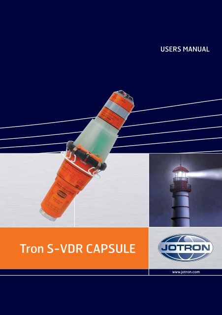
<strong>Tron</strong> S-<strong>VDR</strong> <strong>CAPSULE</strong><br />
www.jotron.com
www.jotron.com<br />
EC Declaration of Conformity, available at www.jotron.com<br />
2<br />
82310_UM_S<strong>VDR</strong>_H
www.jotron.com<br />
Amendment Records<br />
AMEND- INCORP. DATE PAGE(S) VERSION REASON<br />
MENT NO. BY FOR CHANGE<br />
1 ES 14.02.06 44 pages A Kontroll med dokumenter.doc<br />
2 ES 21.03.06 37 B Ch. 6.1 - Self-test<br />
3 ES 13.11.06 28 C IP info<br />
4 ES 18.04.07 Total: 44 D New company name<br />
5 ES 01.10.07 28,29,33,37,38 E Changed text and fuses<br />
6 ES 22.02.08 2,3,4,5,36,41 F Inserted text<br />
7 ES 18.12.08 21 G Additional 4GB flash drive<br />
8 TH 11.06.09 All pages H Layout changes<br />
9 HM 23.01.13 7 H Changed warranty period<br />
10<br />
11<br />
12<br />
13<br />
14<br />
15<br />
16<br />
17<br />
82310_UM_S<strong>VDR</strong>_H<br />
3
www.jotron.com<br />
IMPORTANT<br />
TO PERMANENTLY DISABLE EPIRB<br />
The battery module must be removed and treated according to<br />
chapter 5.6.2 in this manual.<br />
WARNING<br />
USE ONLY THIS EPIRB DURING SITUATIONS<br />
OF GRAVE AND IMMINENT DANGER<br />
FALSE ALERTS<br />
De-alerting sar forces in event of inadvertent activation, or assistance<br />
no longer required<br />
False alarms divert rescue forces from real distress situations.<br />
Intentional false alerts may result in penalties.<br />
Responding to false alarms costs millions annually.<br />
WE NEED YOUR HELP:<br />
1. Remember: activating your beacon is the equivalent of transmitting<br />
a mayday.<br />
2. Follow manufacturer procedures when testing your beacon.<br />
3. If your beacon is activated<br />
• In a non-distress situation, or<br />
• In a distress situation, which resolves, and you no longer<br />
require assistance;<br />
Contact the nearest sar authorities via the most expedetious<br />
means available with the following information:<br />
4<br />
82310_UM_S<strong>VDR</strong>_H
www.jotron.com<br />
Beacon ID number (15 character UIN):<br />
Position (at time of activation):<br />
Date of Activation:<br />
Time of Activation (Time zone):<br />
Duration of Activation:<br />
Beacon make and model:<br />
Vessel Name/ID:<br />
Circumstances/cause (if known):<br />
PRIMARY U.S. POINT OF CONTACT IS THE U.S. COAST<br />
GUARD: PASS BY MOST EXPEDITIOUS, DIRECT MEANS TO<br />
FOR THE PACIFIC:<br />
Pacific area command center (510) 437 3700<br />
FOR THE ATLANTIC/GULF OF MEXICO/ATLANTIC:<br />
Atlantic area command center (757) 398-6390<br />
OR FROM ANY LOCATION:<br />
(800) 323 SAFE<br />
(800) 323 7233<br />
82310_UM_S<strong>VDR</strong>_H<br />
5
www.jotron.com<br />
The information in this book has been carefully checked and is believed to<br />
be accurate. However, no responsibility is assumed for inaccuracies.<br />
CAUTION!<br />
This equipment contains CMOS integrated circuits. Observe handling precautions<br />
to avoid static discharges which may damage these devices.<br />
<strong>Jotron</strong> AS reserves the right to make changes without further notice to any<br />
products or modules described herein to improve reliability, function or design.<br />
<strong>Jotron</strong> AS does not assume any liability arising out of the application<br />
or use of the described product.<br />
WARNING / IMPORTANT<br />
<strong>Jotron</strong> AS is a prime manufacturer of safety equipment designed for rescue<br />
of human lives and their property. For safety equipment to be effective in<br />
line with the design parameters it is important that they are handled, stowed<br />
and maintained in compliance with the manufacturers instructions. <strong>Jotron</strong><br />
AS Cannot be held responsible for any damage caused due to incorrect use<br />
of the equipment or breach of laid down procedures or for failure of any<br />
specific component or other parts of the equipment.<br />
<strong>Jotron</strong> AS does not take any responsibility for improper disassembling/<br />
assembling of the equipment. We strongly recommend all service to be<br />
done by authorized <strong>Jotron</strong> agents. In addition to normal service, <strong>Jotron</strong> AS<br />
agents have the necessary equipment and education to test the operational<br />
functions of the beacon.<br />
6<br />
82310_UM_S<strong>VDR</strong>_H
www.jotron.com<br />
WARRANTY<br />
All goods sold by <strong>Jotron</strong> AS are warranted to be free from defect in workmanship<br />
and material for the period of two (2) years from the date of delivery<br />
(unless stated otherwise and confirmed in writings).<br />
PROVIDED:<br />
(a) <strong>Jotron</strong> AS is given full particulars in writing of any claim prior to<br />
the expiration of such a period and within fourteen days of the dis<br />
covery of the alleged defect.<br />
(b)<br />
(c)<br />
(d)<br />
(e)<br />
(f)<br />
The goods have stored, installed, maintained and used properly<br />
having regard in particular to <strong>Jotron</strong> AS specifications.<br />
Liability shall be limited at <strong>Jotron</strong> AS options to replacement or re<br />
pair or to a sum not exceeding the net invoice value of the defec<br />
tive goods.<br />
Upon request the alleged faulty goods are returned to <strong>Jotron</strong> AS<br />
at the Buyer’s expense.<br />
Unless expressly stipulated in the acceptance of the order <strong>Jotron</strong><br />
AS gives no warranty or guarantee of the fitness or suitability of<br />
the goods for any purpose whether disclosed or otherwise.<br />
All other warranties or conditions expressed or implied are hereby<br />
excluded and <strong>Jotron</strong> AS shall in no circumstances be liable for con<br />
sequential damages.<br />
82310_UM_S<strong>VDR</strong>_H<br />
7
www.jotron.com<br />
Abbreviations and definitions<br />
BAUD<br />
Transmission rate unit of measurement for binary coded data (bit per second).<br />
BIT<br />
Short form of Binary Digit. The smallest element of data in a binary-coded<br />
value.<br />
BITE<br />
Built in test equipment<br />
BPS<br />
Bits Per Second.<br />
CHARACTER STRING<br />
Continuous characters (other than spaces) in a message.<br />
CHECKSUM<br />
The value sent with a binary-coded message to be checked at the receiving<br />
end to verify the integrity of the message.<br />
COSPAS<br />
COsmicheskaya Sistyema Poiska Avariynich Sudov (Space System for the<br />
Search of Vessels in Distress)<br />
CLOCK<br />
A precisely spaced, stable train of pulses generated within an electronic system<br />
to synchronize the timing of digital operations within the system.<br />
DEFAULT<br />
The operator initiates a condition that the navigator assumes automatically if<br />
no other condition.<br />
EPIRB<br />
Emergency Position Indicating Radio Beacon<br />
8<br />
82310_UM_S<strong>VDR</strong>_H
www.jotron.com<br />
FRM<br />
Final Recording Medium<br />
GLOBAL POSITIONING SYSTEM (GPS)<br />
The NAVSTAR Global Positioning System, which consists of orbiting satellites, a<br />
network of ground control stations, and user positioning and navigation equipment.<br />
The system has 24 satellites plus 3 active spare satellites in six orbital<br />
planes about 20,200 kilometers above the earth.<br />
GPS<br />
Global Position System<br />
GPS SYSTEM TIME<br />
Time corrected to Universal Time Coordinated (UTC) and used as the time<br />
standard by the user segment of the GPS system.<br />
IEC<br />
International Electro-technical Commission<br />
IMO<br />
International Maritime Organization<br />
INTERFACE<br />
Electronic circuits that permit the passage of data between different types<br />
of devices; For example, the speed and heading interface circuit permits data<br />
from a speed log and compass to pass to the navigator processor.<br />
ITU<br />
International Telecommunication Union<br />
LED<br />
Light Emitting Diode<br />
LUT<br />
Local User Terminal (Ground Station)<br />
MCC<br />
Mission Control Centre<br />
82310_UM_S<strong>VDR</strong>_H<br />
9
www.jotron.com<br />
PROCESSOR<br />
The processor circuit card in the console that controls system operations and<br />
computes the positioning/navigation solutions.<br />
RCC<br />
Rescue Coordination Centre<br />
SARSAT<br />
Search and Rescue Satellite-Aided Tracking System<br />
SBM<br />
Shore Based Maintenance – as required by SOLAS regulation IV/15.9.2 of<br />
SOLAS 1974 as amended with, in accordance with MSC/Circ. 1039 guidelines<br />
for Shore-Based Maintenance (SBM) of Satellite EPIRBs within 5 years if:<br />
Passenger ships (> 12 passengers) and cargo ships (> 300GT) engaged in International<br />
voyages, shall perform SBM as follows:<br />
• Latest by the date of the EPIRB label with this text, or the battery<br />
Label, whichever is first.<br />
• When this EPIRB becomes due for SBM in accordance with national<br />
requirements.<br />
SOFTWARE<br />
Values programmed and preloaded into memory. The values represent a permanent<br />
set of instructions for running the automatic functions (computations)<br />
of the navigator.<br />
S-<strong>VDR</strong><br />
Simplified Voyage Data Recorder<br />
VHF<br />
Very High Frequency -A set of frequencies in the MHz region<br />
VSWR<br />
Voltage standing wave ratio<br />
10<br />
82310_UM_S<strong>VDR</strong>_H
www.jotron.com<br />
82310_UM_S<strong>VDR</strong>_H<br />
11
www.jotron.com<br />
Table of contents<br />
1 General Description 14<br />
1.1 Epirb Module 14<br />
1.1.1 System Description 14<br />
1.1.2 Signal Detection 15<br />
1.1.3 Distress Location Determination 15<br />
1.1.4 Added Value In The Epirb 17<br />
1.1.5 Epirb Registration 17<br />
1.2 S-<strong>VDR</strong> Server Module 18<br />
2 Technical Specification 20<br />
3 Functional Description 22<br />
3.1 General 22<br />
3.1.1 Capsule Housing 23<br />
3.1.2 S-<strong>VDR</strong> Server Module 23<br />
3.1.3 Epirb Module 23<br />
3.1.4 Battery Module 24<br />
3.1.5 Automatic Release Bracket, FBR-3 24<br />
3.1.6 S-<strong>VDR</strong> Data And Power Connections 25<br />
3.1.6.1 S-<strong>VDR</strong> Data And Power<br />
Connector, Capsule 25<br />
3.1.6.2 S-<strong>VDR</strong> Data And Power Connector,<br />
Bracket 26<br />
3.1.7 Wiring Table S-<strong>VDR</strong> Data And Power<br />
Connection 26<br />
4 Installation 28<br />
4.1 Mounting Bracket FBR-3 28<br />
4.2 Mounting The FBR-3 29<br />
4.3 Mounting Of The Capsule Into The FBR-3 29<br />
4.4 Replacement And Mounting Of The Hydrostatic<br />
Release Mechanism 29<br />
4.5 Junction Box 30<br />
12<br />
82310_UM_S<strong>VDR</strong>_H
www.jotron.com<br />
5 Operating Instructions 34<br />
5.1 FBR-3 Float Free Bracket 34<br />
5.2 Manual Operation Of Epirb Module 34<br />
5.3 Automatic Operation Of Epirb Module 35<br />
5.4 Testing The Epirb Module 35<br />
5.5 Operation Of The S-<strong>VDR</strong> Module 36<br />
5.5.1 Operating Software 36<br />
5.6 Change Of Battery 36<br />
5.6.1 Msc Circ. 1039 36<br />
5.6.2 Battery Disposal 37<br />
5.6.2.1 Incineration 37<br />
5.6.2.2 Land Filling 37<br />
5.6.2.3 Recycling 37<br />
6 Maintenance And Troubleshooting 38<br />
6.1 Epirb Module / Battery Module 38<br />
6.2 Testing Epirb Module 38<br />
6.2.1 Self-Test With Sea Water Contacts<br />
Activated 38<br />
6.2.2 Self-Test With Sea Water Contacts<br />
Deactivated 38<br />
6.3 Maintenance Of Epirb 39<br />
6.3.1 Epirb Module Error Messages 40<br />
6.4 Test Of GPS Receiver Without Transmitters<br />
Activated 41<br />
6.5 S-<strong>VDR</strong> Module 41<br />
7 Service Agents 42<br />
82310_UM_S<strong>VDR</strong>_H<br />
13
www.jotron.com<br />
1 GENERAL DESCRIPTION<br />
The Main parts of the Capsule (<strong>Tron</strong> S-<strong>VDR</strong> <strong>CAPSULE</strong>) are the EPIRB (EPIRB<br />
module) and the S-<strong>VDR</strong> Server module. The Capsule is developed to meet the<br />
regulations and rules for use on ships, vessels and life rafts in the maritime service.<br />
The Capsule meets the following specifications for S-<strong>VDR</strong> and 406MHz<br />
EPIRB for use in search and rescue operations at sea:<br />
• IEC 61996 ed.2<br />
• IEC 61097-2 ed.3.0 (2008)<br />
• IEC 60945 ed.4.0 (2002)<br />
• C/S T.001 and C/S T007 (Nov. 2007)<br />
• IMO MSC.163 (78)<br />
• IMO A.810 (19)<br />
• MED 96/98/EC<br />
1.1 EPIRB MODULE<br />
The Capsule is buoyant, and is designed to automatically release and to automatically<br />
activate the EPIRB in case of an emergency where the Capsule and its<br />
bracket is submerged into the sea. The EPIRB can also be manually operated.<br />
One mounting bracket is available to mount it as an automatic and manual<br />
EPIRB. The purpose of the EPIRB is to give a primary alarm to the search and<br />
rescue authorities. The EPIRB gives an immediate alarm when activated, transmitting<br />
the ID of the ship in distress. The EPIRB will at the same time transmit the<br />
position of the ship. Care must be taken not to activate the EPIRB unless in an<br />
emergency situation, in such cases the user will be held responsible. For periodic<br />
testing a test function is implemented. During the test cycle the EPIRB does<br />
a self-test off the transmitters and the battery status. No emergency signal is<br />
transmitted during the self-test. The battery of the EPIRB will last for at least<br />
168 hours from activation.<br />
1.1.1 SYSTEM DESCRIPTION<br />
The COSPAS/SARSAT system was introduced in 1982 as a worldwide search and<br />
rescue system with the help of satellites covering the earth’s surface. Since the<br />
introduction of the system more than 11200 persons have been rescued by the<br />
COSPAS/SARSAT system. Currently the system consists of 8 different satellites<br />
in a polar orbit Constellation. These satellites cover the entire earth’s surface<br />
and receive the emergency signal from the 406MHz transmitter within the<br />
EPIRB. In addition several geostationary satellites are equipped with a 406MHz<br />
transponder. These satellites are not able to locate the Capsule but will give an<br />
early warning to the rescue forces, minimizing the time from an emergency oc-<br />
14<br />
82310_UM_S<strong>VDR</strong>_H
www.jotron.com<br />
curs till the rescue forces are at the site. Each emergency EPIRB in the system<br />
is programmed with its own unique code, therefore it is vital that the ships data<br />
that is given to the dealer you obtained your <strong>Tron</strong> S-<strong>VDR</strong> <strong>CAPSULE</strong>, is correct.<br />
If the EPIRB is programmed with serial protocol, it is important that the EPIRB is<br />
registered in the database for each country. This database is normally located<br />
in the same country that the ship is registered.<br />
1.1.2 SIGNAL DETECTION<br />
When the EPIRB is activated (manually or automatically) it transmits on the frequencies<br />
121.5MHz and 406.028MHz.A homing signal is emitted on 121.5MHz<br />
and a burst is transmitted on 406.028MHz every 50 second after activation.<br />
This burst contains all necessary information about the ships in distress. After<br />
the EPIRB is activated, the next passing satellite will detect the transmitted<br />
signal and relay it to an antenna at a ground station, called a LUT (Local User<br />
Terminal). For the 121.5MHz signal the satellite must be within line of sight of<br />
both the EPIRB and a ground station.<br />
The ground station or LUT has a 2500 km satellite reception radius centered<br />
at the LUT. In areas without LUT coverage (mostly less populated areas<br />
in the southern hemisphere), signals from the 121.5MHz transmitter will not be<br />
detected by the satellites, only by passing aircraft’s. From the year 2006,no<br />
new satellites will be launched including 121.5MHz receiver, and from the year<br />
2009,satellitedetection of the 121.5MHz EPIRB is terminated. This is not the<br />
case with the 406MHz transmitter, because the satellites have a memory unit,<br />
which stores the signals for relay to the next available LUT giving it a truly global<br />
coverage. Once the signal is received by the LUT, it is processed for location<br />
and sent to a Mission Control Center (MCC).The MCC sorts the alert data according<br />
to geographic search and rescue regions and distributes the information<br />
to the appropriate Rescue Co-ordination Center (RCC), or if outside the national<br />
search and rescue area, to the appropriate MCC that covers the area that<br />
the distress signal was detected. The RCC in turn takes the necessary action to<br />
initiate search and rescue activities.<br />
1.1.3 DISTRESS LOCATION DETERMINATION<br />
The location of the distress signal is determined by taking measurements of the<br />
doppler shift of the EPIRB frequency when the satellite first approach and then<br />
pass the EPIRB. The actual frequency is heard at the time of closest approach<br />
(TCA). Knowing the position of the satellite and using the received doppler signal<br />
information, it is possible to determine the location of the Capsule from the<br />
82310_UM_S<strong>VDR</strong>_H<br />
15
www.jotron.com<br />
satellite at the TCA. At the LUT, actually two positions are calculated. One is the<br />
actual position (A) and the other is the mirror image (B) position [FIG.1.1.3]. A<br />
second satellite pass confirms the correct location (A).With the 406MHzsystem<br />
the real solution can be determined on the first pass with a reliability of<br />
nearly 90% and down to an accuracy of less than 5 km (3.1 miles).<br />
Figure 1.1.3 COSPAS/SARSAT Signal<br />
detection system<br />
16<br />
82310_UM_S<strong>VDR</strong>_H
www.jotron.com<br />
1.1.4 ADDED VALUE IN THE EPIRB<br />
The EPIRB module has been designed to operate with the COSPAS-SARSAT<br />
system and will enhance further the lifesaving capabilities of conventional<br />
beacons. An integrated 12 channel GPS module accepts continuous positional<br />
information from the standard GPS system using 27 satellites providing an<br />
accuracy of approximately 100m.Upon activation of the Capsule in an emergency<br />
situation the positional information is incorporated into the distress<br />
message transmitted to LUT.<br />
The main advantage with integrated GPS in the EPIRB is the rapid response<br />
and positional accuracy providing vital information during a rescue operation<br />
practically eliminating valuable time spent searching for the distressed.<br />
Whenever a distress message transmitted by the EPIRB is detected by a polar<br />
orbit satellite (LEOSAR) the delayed alert remains the same as for non-GPS<br />
integrated EPIRB`s (max.90 min.), but the position accuracy is improved considerably<br />
from a radius of 5 km. to amazing 100m.<br />
Whenever a distress message transmitted by the EPIRB is detected by geostationary<br />
satellite (GEOSAR) the alert is immediate (max.5 min.), still providing<br />
the accurate position of 100m. Please note that the positional accuracy delay<br />
is depending on the actual protocol used and programmed into the EPIRB and<br />
the location of the emergency. The information is based on the capacity of<br />
the LEOSAR/GEOSAR COSPAS-SARSAT system.<br />
1.1.5 EPIRB registration<br />
Normally the MCC will contact the vessel or the contact person registered in a<br />
shipping register and/or an EPIRB register (Ships owner, family member etc.)<br />
before alerting the RCC. This is to determine if the alarm from the EPIRB for<br />
some reason is a false alarm, and an expensive rescue operation can be avoided.<br />
Because of this it is important that the ships data is correct in the shipping<br />
register or in the EPIRB database. The Capsule purchased in some countries<br />
will have a registration form attached to it, it is important that this registration<br />
form is completed by the owner and returned to the place the Capsule was<br />
purchased or to the address specified on the registration form.<br />
Other countries use the already available shipping register to obtain the<br />
necessary information for a vessel in distress, in these countries the ship is al-<br />
82310_UM_S<strong>VDR</strong>_H<br />
17
www.jotron.com<br />
ready registered and no registration form is necessary, however it is vital that<br />
the coding of the EPIRB is kept up to date with data on the ship (nationality,<br />
call.sign, etc.), to minimize the time from an alarm to the start of the search<br />
and rescue operation.<br />
Reprogramming the EPIRB can be done at authorized <strong>Jotron</strong> AS agents in<br />
more than 250 different places throughout the world. If you are a resident of<br />
the United States, you must register this beacon with the National Oceanic<br />
and Atmospheric Administration (NOAA) using the registration card included<br />
with the unit. Fill out the form and send it to: SARSAT Beacon Registry, NOAA-<br />
SARSAT, E/SP3, FB4, Room 3320, 5200 Auth Road, Suitland, MD 20746-<br />
4304 Vessel owners shall advise NOAA in writing upon change of vessel or<br />
EPIRB ownership. Transfer of EPIRB to another vessel, or any other change in<br />
registration information, NOAA will provide registrants with proof of registration<br />
and change of registration postcards.<br />
1.2 S-<strong>VDR</strong> SERVER MODULE<br />
The S-<strong>VDR</strong> Server module consists of S-<strong>VDR</strong> Server module house including<br />
Flashdisc. The S-<strong>VDR</strong> Server module is DC powered from the ship via the bracket<br />
connector. The S-<strong>VDR</strong> data is fed from the ships S-<strong>VDR</strong> system to the<br />
S-<strong>VDR</strong> Server module through the same connector. When the Capsule leaves<br />
the automatic release bracket, all electrically power and data connections<br />
between the ship S-<strong>VDR</strong> system and the S-<strong>VDR</strong> Server module inside the<br />
capsule is broken.<br />
18<br />
82310_UM_S<strong>VDR</strong>_H
www.jotron.com<br />
82310_UM_S<strong>VDR</strong>_H<br />
19
www.jotron.com<br />
2 TECHNICAL SPECIFICATIONS<br />
STANDARDS<br />
ENVIRONMENTAL<br />
Temperature range<br />
Degree of protection<br />
GENERAL<br />
External Supply voltage<br />
for module<br />
Current consumption<br />
S-<strong>VDR</strong><br />
Locator lights<br />
Test light<br />
Frequency range<br />
Programming<br />
Operating life EPIRB<br />
Dimension<br />
Weight<br />
Material housing<br />
Antennas 406.028MHz,<br />
121.5MHz<br />
Antenna GPS<br />
IEC 61097-2 ed.2 annex D and EN 60945 ed.4<br />
2002-08<br />
-20°C to +55°C (operating) -40°C to +70°C<br />
(storage)<br />
10 m depth at 5min<br />
12 – 30 VDC<br />
0.25 A at 24VDC<br />
Flashing Xenon light<br />
Test LED<br />
406,028 / 121,5MHz<br />
IR port, 2400 bit/s.<br />
168 hours at -20°C<br />
L = 570 mm Ø = 188 mm.<br />
Approx. 3.5 kg<br />
Polycarbonate with 10% glass fiber.<br />
Built in, vertical polarization, omnidir.<br />
Built in GPS patch antenna.<br />
406MHz TRANSMITTER<br />
Frequency<br />
406.028MHz +2kHz / -5kHz<br />
Output Power<br />
5W ± 2dB<br />
Protocols<br />
MMSI Standard Location (long)<br />
Serial EPIRB Standard (long)<br />
Modulation<br />
Phase modulation 1.1 ±0.1rad.<br />
Data Encoding Bi Phase L.<br />
Stability Short term: ≤ 2*10-9. Medium term: ≤ 2*10-9.<br />
Residual noise: ≤ 3*10-9.<br />
Bit rate<br />
400 b/s<br />
20<br />
82310_UM_S<strong>VDR</strong>_H
www.jotron.com<br />
121,5MHz TRANSMITTER<br />
Frequency<br />
121.500MHz ± 10ppm.<br />
Output Power<br />
>75mW<br />
Modulation<br />
A9 AM. The modulation starts with a letter V for <strong>VDR</strong><br />
in Morse code, then a sweep tone from max 1600Hz<br />
to min 300Hz is transmitted. Sweep range >700Hz,<br />
Downward / Upward Sweep rate 2-3 Hz.<br />
S-<strong>VDR</strong> MODULE<br />
Flash disk<br />
Interface<br />
Cable length<br />
GPS RECEIVER<br />
Type<br />
Channels.<br />
Accuracy<br />
Frequency<br />
2GB, 1.7GB free or 4 GB, 3.7 GB free.<br />
Ethernet 10BaseT (10Mbit)<br />
< 100 m<br />
Navman Jupiter, 12 channel GPS receiver<br />
12 channels<br />
Better than 4 sec. of an arc.<br />
1575.42 MHz<br />
MOUNTING BRACKET<br />
Dimensions:<br />
Height: 695 mm, Width: 166 mm, Depth: 112mm<br />
Weight:<br />
4.6 Kg<br />
Hydrostatic release Hammar H20<br />
Material Stainless Steel AISI 316 (SIS 2343)<br />
BATTERY MODULE<br />
8 PCs SAFT LSH20 Lithium-Thionyl chloride<br />
(Li-SOCL2). Connected in series and parallel.<br />
Fuse in each cell.<br />
82310_UM_S<strong>VDR</strong>_H<br />
21
www.jotron.com<br />
3 FUNCTIONAL DESCRIPTION<br />
3.1 GENERAL<br />
The <strong>Tron</strong> S-<strong>VDR</strong> Capsule consists of ten parts.<br />
1<br />
2<br />
3<br />
4<br />
5<br />
6<br />
1. Main EPIRB switch<br />
2. Antenna board<br />
3. Upper housing<br />
4. Equator ring with gasket<br />
5. EPIRB module<br />
6. Recovery ring with mounting<br />
clips<br />
7. S-<strong>VDR</strong> Server module<br />
8. Lower housing<br />
9. Battery module<br />
10. S-<strong>VDR</strong> Connector<br />
7<br />
8<br />
9<br />
10<br />
Figure 3.1, Cut-through S-<strong>VDR</strong> Capsule<br />
22<br />
82310_UM_S<strong>VDR</strong>_H
www.jotron.com<br />
3.1.1 <strong>CAPSULE</strong> HOUSING<br />
The capsule module consists of upper and lower house mounted together with<br />
an equator ring with gasket and locking pin.<br />
3.1.2 S-<strong>VDR</strong> SERVER MODULE<br />
The S-<strong>VDR</strong> Server module consists of S-<strong>VDR</strong> Server module house including<br />
Flash disc and a double-sided PCB board with power regulator and PC circuits.<br />
The S-<strong>VDR</strong> Server module is DC powered from the ship via the bracket connector.<br />
The S-<strong>VDR</strong> data is fed from the ships S-<strong>VDR</strong> system to the S-<strong>VDR</strong> Server<br />
module through the same connector. When the capsule leaves the automatic<br />
release bracket, all electrically power and data connections between the ship<br />
S-<strong>VDR</strong> system and the S-<strong>VDR</strong> Server module inside the capsule is broken.<br />
3.1.3 EPIRB MODULE<br />
The EPIRB module consists of four printed circuit boards, which are mounted in<br />
the upper housing:<br />
1. The main board w/GPS patch antenna, Xenon flash and an indicator LED<br />
2. Antenna board. (121.5 / 406 MHz)<br />
3. GPS interface board<br />
4. GPS receiver<br />
For automatic activation of the EPIRB module, put the capsule in the upright<br />
position into the water, and the transmission starts when the seawater completes<br />
the circuit between the two external electrodes (sea water contacts).<br />
When the capsule is mounted in the automatic release bracket mechanism,<br />
there is a safety switch in the EPIRB module, a reed contact activated by a<br />
magnet at the FBR-3 bracket, which disables the seawater contacts. See figure<br />
3.1.5.<br />
If submerged in water, the hydrostatic release mechanism will release the<br />
capsule at a depth of 2-4 meters. The transmission will start when the circuit<br />
between the seawater contacts is closed and the capsule is out of the bracket.<br />
The EPIRB module may be manually activated with the main switch, and is then<br />
independent of seawater contacts. The EPIRB module will also operate while<br />
placed in the bracket when manually activated.<br />
The capsule may easily be released from the mounting bracket manually.<br />
82310_UM_S<strong>VDR</strong>_H<br />
23
www.jotron.com<br />
3.1.4 BATTERY MODULE<br />
The Battery module is feeding the EPIRB module with 7.2VDC power to keep the<br />
EPIRB transmitters active for 168 hours when activated, and for test sequences.<br />
The battery module consists of eight SAFT LSH20 Lithium-Thionyl chloride<br />
(Li-SOCL2) batteries connected in series and parallel and is attached inside<br />
the lower house.<br />
3.1.5 AUTOMATIC RELEASE BRACKET, FBR-3<br />
The FBR-3 bracket is the docking station for the capsule. A connector and a<br />
cable connected to the ships 24VDC power and S-<strong>VDR</strong> data keeps the S-<strong>VDR</strong><br />
Server module alive and working when the capsule is in the bracket.<br />
Hydrostatic release<br />
Magnet<br />
Figure 3.1.5, FBR-3 bracket<br />
Springloaded arm<br />
S-<strong>VDR</strong> connector<br />
24<br />
82310_UM_S<strong>VDR</strong>_H
www.jotron.com<br />
3.1.6 S-<strong>VDR</strong> Data and Power connections<br />
3.1.6.1 S-<strong>VDR</strong> Data and Power connector, capsule<br />
Figure 3.1.6.1, S-<strong>VDR</strong> female connector in capsule.<br />
82310_UM_S<strong>VDR</strong>_H<br />
25
www.jotron.com<br />
3.1.6.2 S-<strong>VDR</strong> DATA AND POWER CONNECTOR, BRACKET<br />
Figure 3.1.6.2, S-<strong>VDR</strong> male connector in bracket.<br />
3.1.7 WIRING TABLE S-<strong>VDR</strong> DATA AND POWER CONNECTION<br />
Pin nr Wire color bracket Wire color Function<br />
and connection box inside capsule<br />
1 Blue White Ethernet Tx +<br />
2 Green Red Ethernet Tx -<br />
3 Brown Green Ethernet Rx +<br />
4 Yellow Brown Ethernet Rx -<br />
5 Pink Yellow + Supply<br />
6 Grey Black GND<br />
26<br />
82310_UM_S<strong>VDR</strong>_H
www.jotron.com<br />
82310_UM_S<strong>VDR</strong>_H<br />
27
www.jotron.com<br />
4 INSTALLATION<br />
4.1 MOUNTING BRACKET FBR-3<br />
The bracket is an automatic release bracket. Not all details are shown at this<br />
picture.<br />
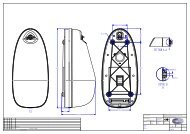
Figure 4.1, Part of FBR-3 bracket with measures<br />
28<br />
82310_UM_S<strong>VDR</strong>_H
www.jotron.com<br />
4.2 MOUNTING THE FBR-3<br />
Bolt the unit to the vessel using the mounting holes. The Float Free Bracket<br />
FBR-3 must be connected to the fixed installation S-<strong>VDR</strong> installation through<br />
the junction box according to the connection diagram in paragraph 3.1.7.<br />
When the Capsule is mounted in the FBR-3 release mechanism, it operates as<br />
a float free automatic unit.<br />
Therefore it is important that the bracket is mounted in a place where there are<br />
no obstructions that can endanger the automatic release of the beacon.<br />
The location where the bracket is mounted should be as high as possible on the<br />
vessel, protected from environmental conditions such as direct sea spray, chemicals,<br />
oil, exhaust and vibrations. The location must also be easily accessible<br />
for testing and maintenance.<br />
4.3 MOUNTING OF THE <strong>CAPSULE</strong> INTO THE FBR-3<br />
Strain the spring loaded lower arm with the connector at the lower part of the<br />
bracket. Place the higher part of the Capsule into the top grip of the bracket<br />
with the main switch facing out. Then push the Capsule into the bracket and<br />
slowly release the lower arm, checking that the connector pins at the bracket<br />
hits the connector holes at the Capsule. Place the locking bolt into the corresponding<br />
holes in the lower arm, and mount the clamp at the bolt.<br />
4.4 REPLACEMENT AND MOUNTING OF THE HYDROSTATIC RELEASE<br />
MECHANISM<br />
The Hydrostatic Release Mechanism must be mounted before the Capsule is<br />
placed into the FBR-3 bracket. To replace the Hydrostatic Release Mechanism,<br />
remove the Capsule from the bracket:<br />
1. Remove the clamp on the locking bolt on the spring-loaded lower arm.<br />
2. Remove the locking bolt.<br />
3. Whilst holding the Capsule, strain the spring-loaded lower arm and gently<br />
remove the Capsule from the bracket.<br />
4. Now the H20 unit is accessible. Unscrew the plastic bolt (3) and remove the<br />
unit.<br />
5. Replace the old unit with a new one and tag in expiration date for 2 more<br />
years.<br />
6. Screw the new plastic bolt on. Make sure the distance piece (4,5,6) is in place<br />
on the plastic bolt. Tighten the bolt using hand-force only until rubber<br />
seal (5) starts to compress. Replace the Capsule into the bracket, reversing<br />
paragraph 1, 2 and 3.<br />
82310_UM_S<strong>VDR</strong>_H<br />
29
www.jotron.com<br />
4.5 JUNCTION BOX<br />
The junction box is connected to the connector on the FBR-3 bracket with a<br />
special cable.<br />
All connections to the ships systems are done at the Junction box. See figure<br />
4.5.a.<br />
The two fuses are for protection of + DC supply and Ground.<br />
The fuses act as short circuit protection and will automatically reset some minutes<br />
after the short circuit is removed.<br />
Ingress protection of Junction box included bushing nipples: IP66<br />
30<br />
82310_UM_S<strong>VDR</strong>_H
www.jotron.com<br />
Figure 4.5.a, Junction box with lid removed<br />
82310_UM_S<strong>VDR</strong>_H<br />
31
www.jotron.com<br />
Figure 4.5.b, Junction box with measures<br />
32<br />
82310_UM_S<strong>VDR</strong>_H
www.jotron.com<br />
82310_UM_S<strong>VDR</strong>_H<br />
31
www.jotron.com<br />
5 OPERATING INSTRUCTIONS<br />
5.1 FBR-3 FLOAT FREE BRACKET<br />
When the capsule is mounted in the FBR-3 bracket release mechanism, it operates<br />
as a float free automatic unit.<br />
5.2 MANUAL OPERATION OF EPIRB MODULE<br />
Figure 5.2, EPIRB Main switch<br />
The manual operation can be done when the capsule is mounted in the bracket<br />
or when the capsule is removed from the bracket.<br />
Break the seal on the main switch and pull the locking pin. Push in the leftmost<br />
part of switch mechanism and the switch will automatically go to the ON (Emergency)<br />
position.<br />
The red indicator lamp and the Xenon flash on the main board will start operating,<br />
indicating that the EPIRB module is active.<br />
NOTE!<br />
The EPIRB module performs a complete self-test before any emergency signals<br />
are transmitted. The Transmitters will start after approx. 70 seconds. At the<br />
same time GPS receiver is started. This is done to prevent the GPS receiver to<br />
start in TEST position. Turning the switch back to the READY position stops the<br />
transmission. If the Capsule is out of the bracket, make sure the battery compartment<br />
is dry to prevent activation of the seawater contacts.<br />
34<br />
82310_UM_S<strong>VDR</strong>_H
www.jotron.com<br />
5.3 AUTOMATIC OPERATION OF EPIRB MODULE<br />
When the capsule is removed from the release mechanism and placed into water<br />
it will automatically activate due to the seawater contacts. Transmission will<br />
stop when the capsule is lifted out of the water, and if necessary dried off.<br />
When placed in the automatic release mechanism the seawater contacts are<br />
disabled. When the mechanism is reaching a depth of 2-4 meters, the capsule<br />
will be released and transmission will start automatically.<br />
NOTE!<br />
There is a time delay of approx. 10 seconds of activation/deactivation with the<br />
seawater contact.<br />
5.4 TESTING THE EPIRB MODULE<br />
IMPORTANT:<br />
The self-test should be performed only within the first 5 minutes of any<br />
hour.<br />
To perform the self-test, the Capsule has to be removed from the bracket.<br />
WARNING<br />
Releasing the Capsule from the bracket will interrupt all<br />
connections between the ships S-<strong>VDR</strong> system and the FRM<br />
inside the Capsule, and all recordings will be interrupted. The<br />
regulations require the Capsule not to be removed for more<br />
than 10 minutes.<br />
1. Press the spring-loaded switch on top of the Capsule to the TEST position,<br />
see paragraph 5.2. Keep hands and other objects away from the upper part of<br />
the Capsule. (Away from the antenna).<br />
2. A successful test will consist of a series of blinks on the LED test-indicator,<br />
followed by a continuous light and a strobe flash after app.15 seconds.<br />
3. If the procedure fails to end up with a continuous light, this indicates a fault in<br />
the EPIRB module. (See paragraph 6.2.1).<br />
82310_UM_S<strong>VDR</strong>_H<br />
35
www.jotron.com<br />
4. Release the switch and put the Capsule back into the bracket.<br />
What the self-test actually does is first to wait app.15 seconds to allow the reference<br />
oscillator inside the EPIRB module to warm up. Then a short burst is<br />
transmitted by the 121.5MHz transmitter, while the output level of the transmitter<br />
is checked. Finally, a test signal is transmitted by the 406 transmitter. During<br />
this test signal the battery voltage, output power and frequency is checked.<br />
While testing the 406 MHz transmitter a test message is transmitted. This test<br />
message is coded with a special synchronization code and will not be detected<br />
by the COSPAS/SARSAT satellites. The purpose of this test message is to control<br />
the actual coding of the EPIRB module. This can be done with the <strong>Jotron</strong> AS<br />
test unit <strong>Tron</strong> UNIDEC or another EPIRB tester.<br />
5.5 OPERATION OF THE S-<strong>VDR</strong> MODULE<br />
5.5.1 OPERATING SOFTWARE<br />
The software operating system of the S-<strong>VDR</strong> module is Linux. The system includes<br />
SAMBA, which enables other software platforms to access Linux file system,<br />
and a FTP (File Transfer Platform) server.<br />
For more detailed information, see the Technical manual.<br />
5.6 CHANGE OF BATTERY<br />
5.6.1 MSC CIRC. 1039<br />
If the S-<strong>VDR</strong> Capsule is the main EPIRB on board the ship, the rules of MSC CIRC<br />
1039 apply, and the battery must be changed at an authorized workshop.<br />
If the S-<strong>VDR</strong> Capsule is the second EPIRB on board the ship, authorized personnel<br />
can change the battery on board.<br />
To change the battery, the lower Capsule Assembly is replaced with a new one.<br />
1. Remove the clips and the recovery ring around the equator ring.<br />
2. Remove split pin and pull the U-shaped bolt from the equator ring.<br />
3. Remove the equator belt by pressing it out from the housing.<br />
4. Separate the lower and upper part of the capsule assembly.<br />
5. Unplug the battery connector, the S-<strong>VDR</strong> connector and the seawater<br />
connector.<br />
36<br />
82310_UM_S<strong>VDR</strong>_H
www.jotron.com<br />
6. Check that the new battery is marked with date of expiration.<br />
7. Place the new gasket on the battery housing.<br />
8. Connect the battery connector, the S-<strong>VDR</strong> connector and the seawater<br />
connector.<br />
9. Replace the upper part, taking care that the gasket is correctly fitted and<br />
taking note of the orientation marks on the two housings.<br />
10. Replace the equator ring, U-shaped bolt and split pin.<br />
11. Replace the clips and the recovery ring around the equator ring.<br />
12. Perform a Self-test.<br />
5.6.2 BATTERY DISPOSAL<br />
Dispose in accordance with applicable regulations, which vary from country to<br />
country.(In most countries, the thrashing of used batteries is forbidden and the<br />
end-users are invited to dispose them properly, eventually through non-profit<br />
organizations, mandated by local governments or organized on a voluntary<br />
basis by professionals).Lithium batteries should have their terminals insulated<br />
prior to disposal.<br />
5.6.2.1 INCINERATION<br />
Incineration should never be performed by battery users but eventually by trained<br />
professionals in authorized facilities with proper gas and fumes treatment.<br />
5.6.2.2 Land filling<br />
Leachability regulations (mg/l)<br />
Component Leachability EC limit EPA Other*<br />
Iron 100 5<br />
Nickel 100 500 2 0,5<br />
* applicable to France<br />
5.6.2.3 Recycling<br />
Send to authorized recycling facilities, eventually through licensed waste carrier.<br />
82310_UM_S<strong>VDR</strong>_H<br />
37
www.jotron.com<br />
6 MAINTENANCE AND TROUBLESHOOTING<br />
6.1 EPIRB module / battery module<br />
The EPIRB should be tested and batteries replaced according to MSC<br />
circ.1039. See chapter 5.6.1.<br />
6.2 Testing EPIRB module<br />
IMPORTANT:<br />
The self-test should be performed only within the first 5 minutes of any<br />
hour.<br />
6.2.1 Self-test with sea water contacts activated<br />
To perform the self-test with seawater contacts activated, the capsule has to<br />
be removed from the release mechanism. Authorized personnel should annually<br />
test the seawater contacts.<br />
WARNING<br />
Releasing the Capsule from the bracket will interrupt all<br />
connections between the ships S-<strong>VDR</strong> system and the FRM<br />
inside the Capsule, and all recordings will be interrupted.<br />
The regulations require the Capsule not to be removed for<br />
more than 10 minutes.<br />
Remove the capsule from the release mechanism and go to paragraph 6.2.2.<br />
6.2.2 Self-test with sea water contacts deactivated<br />
Turn the switch to the «TEST» position. The red indicator will start flashing<br />
for approx. 15 sec. This is to allow the internal TCXO (Temperature Controlled<br />
Xtal Oscillator) to be stable. Then the output power of both transmitters are<br />
checked, the battery voltage and the PLL of the 406 Transmitter. A complete<br />
message on the 406 Frequency is transmitted, with inverted frame sync.<br />
If all tests are passed there will be one flash in the Xenon bulb, and the red<br />
indicator light will turn on and stay on until the switch is released.<br />
A successful test will then consist of a series of rapid flashes in the test indicator,<br />
followed by one Xenon flash and continuous light in the test indicator.<br />
38<br />
82310_UM_S<strong>VDR</strong>_H
www.jotron.com<br />
Any other behavior indicates a fault in the EPIRB module.<br />
6.3 Maintenance of EPIRB<br />
WARNING<br />
Releasing the Capsule from the bracket will interrupt all<br />
connections between the ships S-<strong>VDR</strong> system and the FRM<br />
inside the Capsule, and all recordings will be interrupted.<br />
The regulations require the Capsule not to be removed for<br />
more than 10 minutes.<br />
Every Month:<br />
Perform EPIRB self-test. (See chapter 6.2.1).<br />
What the self-test actually does is to send out a short test signal on 121,5 and<br />
406,028Mhz,testing the output of the transmitter. While transmitting the test<br />
signal, the battery voltage, output power and phase lock is tested. During the<br />
test of the 406Mhz transmitter a test message is transmitted, this test message<br />
is coded with a special synchronization code and will not be recognized<br />
as real alert by the COSPAS/SARSAT satellites. Carry out visual inspection for<br />
defects on both the Capsule and Bracket.<br />
The Capsule should be easily removed and replaced in the Bracket. Make sure<br />
that the Capsule and Bracket is not painted or otherwise covered with chemicals,<br />
oil, etc. Check the expiry date of the<br />
EPIRB Battery and the Hydrostatic Release Mechanism. Check the presence<br />
of a firmly attached lanyard in good condition and that it is neatly stowed and<br />
is not tied to the vessel or the mounting bracket. If the <strong>Tron</strong> S-<strong>VDR</strong> <strong>CAPSULE</strong><br />
is the main EPIRB on board, these rules must be followed: Every 12th Month:<br />
Perform extended annual test according to IMO’s MSC/Circ.1040 (Annual<br />
testing of 406 MHz satellite EPIRBs) as required by SOLAS IV/15.9.This test<br />
can be carried out by one of <strong>Jotron</strong> AS authorized representatives or any<br />
other service provider in possession of a <strong>Tron</strong> UNIDEC, <strong>Tron</strong> DEC or any other<br />
Cospas/Sarsat EPIRB tester/decoder.<br />
The test ensures that the EPIRB is within its specifications and complies with<br />
IMO and the COSPAS/SARSAT system. Documented proof of test or Test Cer-<br />
82310_UM_S<strong>VDR</strong>_H<br />
39
www.jotron.com<br />
tificate containing test results and EPIRB data issued by service provider must<br />
be kept onboard for future inspections the next 12 months.<br />
Every 2nd Year:<br />
Hydrostatic Release Mechanism including Plastic Bolt on the Float Free Brackets<br />
must be replaced.(Check expiry date on label).<br />
Every 5th Year:<br />
The EPIRB Battery must be replaced every 5th year, unless otherwise instructed<br />
by the vessel flag state or local authorities.(Check expiry date on<br />
label).<br />
6.3.1 EPIRB module error messages<br />
If the self-test detects a fault in the EPIRB module one or more of the following<br />
indications are shown:<br />
1. Flashing LED for 15 sec. followed by one (1) flash, no Xenon flash:<br />
Error: Low power on 406 MHz transmitter<br />
2. Flashing LED for 15 sec. followed by two (2) flashes, no Xenon flash:<br />
Error: Low battery voltage<br />
3. Flashing LED for 15 sec. followed by three (3) flashes, no Xenon flash:<br />
Error: Low power on 121.5 MHz transmitter<br />
4. Flashing LED for 15 sec. followed by four- (4) flash, no Xenon flash:<br />
Error: PLL on 406 Transmitter out of lock<br />
5. Five (5) flashes, no Xenon flash:<br />
Error: EPIRB module not programmed or programming not complete<br />
40<br />
82310_UM_S<strong>VDR</strong>_H
www.jotron.com<br />
6.4 Test of GPS receiver without transmitters activated<br />
This information is restricted and is included in the Technical manual only.<br />
6.5 S-<strong>VDR</strong> module<br />
In accordance with SOLAS Chapter V Regulation 18.8; -the S-<strong>VDR</strong> shall be<br />
subject to an annual performance checks. A ship required under International<br />
rules to carry a functioning simplified voyage data recorder (S-<strong>VDR</strong>), and<br />
under Paris Memorandum Port State Control requirements a ship may be<br />
detained if the S-<strong>VDR</strong> is not functioning properly.<br />
The person carrying out the annual checks should be approved by the ship’s<br />
Flag Administration and show evidence that he has been authorized by the<br />
S-<strong>VDR</strong> manufacturer to service the particular make and model of equipment.<br />
To act in accordance with the requirements for bit-error-rate monitoring the<br />
status of the <strong>Tron</strong> S-<strong>VDR</strong> flash disk memory is to be checked during the annual<br />
survey to be specified by the S-<strong>VDR</strong> manufacturers procedures.<br />
82310_UM_S<strong>VDR</strong>_H<br />
41
www.jotron.com<br />
7 SERVICE AGENTS<br />
Please look at www.jotron.com for Marine Service Agents.<br />
<strong>Jotron</strong> Group subsidiary companies:<br />
<strong>Jotron</strong> UK Ltd.<br />
Crosland Park, Off Crowhall Road<br />
Cramlington<br />
Northumberland NE23 1LA<br />
United Kingdom<br />
Tel +44 1670 712000<br />
Fax +44 1670 590265<br />
E-mail: sales@jotron.com<br />
<strong>Jotron</strong> Asia Pte. Ltd.<br />
Changi Logistics Center<br />
19 Loyang Way #04-26<br />
Singapore 508724<br />
Tel +65 65426350<br />
Fax +65 65429415<br />
E-mail: sales@jotron.com<br />
<strong>Jotron</strong> USA, Inc.<br />
10645 Richmond Avenue, Suite 140<br />
Houston, TX 77042<br />
USA<br />
Tel +1 713 268 1061<br />
Fax +1 713 268 1062<br />
E-mail: sales@jotron.com<br />
42<br />
82310_UM_S<strong>VDR</strong>_H
www.jotron.com


