User Manual - John Preston
User Manual - John Preston User Manual - John Preston
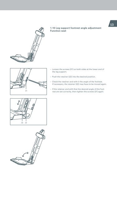
1.10 Leg support footrest angle adjustment Function seat 13 – Loosen the screws [21] on both sides at the lower end of the leg support. – Push the retainer [22] into the desired position. – Check the retainer and with it the angle of the footrest. If necessary, the retainer [22] may have to be moved again. 21 – If the retainer and with that the desired angle of the footrest are set correctly, then tighten the screws [21] again. 22 22
14 1.11 Leg support footrest length adjustment Standard and function seats – Loosen the three screws [23] underneath the footrest. A B C – The length can be adjusted by inserting the screws in one of the three sets of holes A, B or C. – Screw the footrest [24] into the desired position. 23 23 23 24
- Page 1 and 2: Adventure A10 Informationen für Th
- Page 3 and 4: Contents 1 Mechanical adjustments
- Page 5 and 6: 1 Mechanical adjustments to the adv
- Page 7 and 8: 1.3 Armrest sideways adjustment 9 -
- Page 9 and 10: 1.5 Backrest angle of inclination a
- Page 11 and 12: 10 1.7 Seat length adjustment Funct
- Page 13: 12 1.9 Leg support length adjustmen
- Page 17 and 18: 16 1.13 Adjusting the chassis sprin
- Page 19 and 20: 18 31 1.14 Setting the direction in
- Page 21 and 22: 20 1.16 Setting the seat position S
- Page 23 and 24: 22 1.17.2 Mudguards for the powered
- Page 25 and 26: 2 Settings on the control unit 24 2
- Page 27 and 28: 26 Turning speed - Determines the m
- Page 29 and 30: 28 Speed reduction This parameter c
- Page 31 and 32: 30 2.6 Changing the parameters Afte
- Page 33 and 34: 32 2.8 Parameter table 2.8.1 advent
- Page 35 and 36: 34 2.8.3 adventure version 12 km/h
- Page 37 and 38: 36 Drive symbol flashes Exclamation
- Page 39 and 40: 38 Drive symbol flashes Exclamation
- Page 41 and 42: 40 Interface symbol flashes Exclama
- Page 43 and 44: 42 Complete seat unit* flashes Inte
- Page 45 and 46: 44 Brake symbol flashes Battery cap
1.10 Leg support footrest angle adjustment<br />
Function seat<br />
13<br />
– Loosen the screws [21] on both sides at the lower end of<br />
the leg support.<br />
– Push the retainer [22] into the desired position.<br />
– Check the retainer and with it the angle of the footrest.<br />
If necessary, the retainer [22] may have to be moved again.<br />
21<br />
– If the retainer and with that the desired angle of the footrest<br />
are set correctly, then tighten the screws [21] again.<br />
<br />
<br />
22 22


