Operating Manual (PDF) - John Morris Scientific
Operating Manual (PDF) - John Morris Scientific
Operating Manual (PDF) - John Morris Scientific

Create successful ePaper yourself
Turn your PDF publications into a flip-book with our unique Google optimized e-Paper software.
ESC<br />
130<br />
60<br />
180<br />
30<br />
10 220<br />
°C<br />
ENERGENCY STOP<br />
OFF<br />
ON<br />
<strong>Operating</strong> <strong>Manual</strong><br />
SemiChill Recirculating Coolers<br />
Professional Series<br />
T<br />
NOT-AUS<br />
SC 2500a<br />
air cooled<br />
SC 2500<br />
SC 2500w<br />
water cooled<br />
Software version 3.00<br />
Printed in Germany<br />
Changes without prior notification reserved<br />
1.951.4571 BE4 06/08<br />
Innovative Temperature Technology<br />
JULABO Labortechnik GmbH<br />
77960 Seelbach / Germany<br />
+49 (0) 7823 / 51-0<br />
+49 (0) 7823 / 24 91<br />
info@julabo.de<br />
www.julabo.de<br />
19514571.doc 19.06.08
Content<br />
Page<br />
<strong>Operating</strong> manual 2 ... 12<br />
<strong>Operating</strong> instructions 13 ... 71<br />
Congratulations!<br />
You have made an excellent choice.<br />
JULABO thanks you for the trust you have placed in us.<br />
This operating manual has been designed to help you gain an understanding of the principles of<br />
operating and possibilities of our recirculating coolers. For optimum utilization of all functions, we<br />
recommend that you thoroughly study this manual prior to beginning operation.<br />
Quality Management System<br />
We a r e<br />
ISO 9001<br />
2000<br />
c e r<br />
t<br />
i<br />
f<br />
i e d<br />
The JULABO Quality Management System:<br />
Development, production and distribution of temperature application instruments<br />
for research and industries conform to the requirements according to<br />
DIN EN ISO 9001:2000.<br />
Certificate Registration No. 01 100044846<br />
Unpacking and checking<br />
Unpack the recirculating cooler and accessories and check for damages incurred during transit. These<br />
should be reported to the responsible carrier, railway, or postal authority, and a request for a damage<br />
report should be made. These instructions must be followed fully for us to guarantee our full support of<br />
your claim for protecting against loss from concealed damage. The form required for filing such a claim<br />
will be provided by the carrier.<br />
2
Recirculating Cooler<br />
TABLE OF CONTENTS<br />
<strong>Operating</strong> manual.................................................................................................................. 5<br />
Description .......................................................................................................................... 5<br />
Operator responsibility – Safety recommendations ............................................................ 6<br />
EC Declaration of Conformity.............................................................................................. 8<br />
Warranty conditions ............................................................................................................ 9<br />
Technical specifications .................................................................................................... 10<br />
<strong>Operating</strong> instructions ......................................................................................................... 13<br />
1. <strong>Operating</strong> controls and functional elements ................................................................. 13<br />
2. Safety notes for the user .............................................................................................. 16<br />
3. Preparations ................................................................................................................. 16<br />
3.1. Installation................................................................................................................ 16<br />
3.2. Connecting the external system............................................................................... 17<br />
3.2.1. External control............................................................................................... 18<br />
3.3. Bath fluids ................................................................................................................ 18<br />
3.3.1. Tubing............................................................................................................. 20<br />
3.4. Filling........................................................................................................................ 20<br />
3.5. Draining.................................................................................................................... 21<br />
4. <strong>Operating</strong> procedures................................................................................................... 22<br />
4.1. Power connection .................................................................................................... 22<br />
4.2. Switching on / Start - Stop ....................................................................................... 22<br />
5. Setting the temperatures .................................................................................... 23<br />
6. Safety installations, warning functions................................................................ 24<br />
6.1. Excess temperature protection ................................................................................ 24<br />
6.1.1. Early warning system, low level protection..................................................... 25<br />
6.2. Over and Sub temperature warning functions.......................................................... 26<br />
6.2.1. Change-over of the warning function to shutdown function............................ 27<br />
7. Menu functions ................................................................................................... 28<br />
7.1. MENU PUMP - Setting the pump pressure.............................................................. 29<br />
7.2. MENU CONTROL – Control parameters ................................................................. 30<br />
7.2.1. CONTROL – internal / external control........................................................... 30<br />
7.2.2. SELFTUNING................................................................................................. 31<br />
7.2.3. DYN INT - Dynamic internal ........................................................................... 32<br />
7.2.4. Control parameters – XP, TN, TV internal...................................................... 32<br />
3
7.2.5. COSPEED - external .......................................................................................34<br />
7.2.6. Control parameters – XPU, XP, TN, TV external ............................................35<br />
7.3. MENU CONFIG - configuration.................................................................................36<br />
7.3.1. SETPOINT – Keypad control or remote control ..............................................37<br />
7.3.2. A-START – Autostart.......................................................................................38<br />
7.3.3. OFF-MODE – Pump motor on / off..................................................................39<br />
7.3.4. RESET – Factory settings ...............................................................................39<br />
7.3.5. ACTVAR - actuating variable...........................................................................40<br />
7.3.6. TIME / DATE – setting time and date ..............................................................41<br />
7.4. MENU SERIAL - BAUDRATE, HANDSHAKE, PARITY ...........................................42<br />
7.5. MENU LIMITS...........................................................................................................43<br />
7.6. MENU PROGRAM – Integrated programmer ...........................................................45<br />
7.7. MENU ADJUST – ATC Absolute Temperature Calibration ......................................49<br />
7.8. MENU ANALOG – Analog inputs/outputs.................................................................53<br />
8. Troubleshooting guide / Error messages.......................................................................59<br />
9. Safety recommendations...............................................................................................61<br />
10. Electrical connections....................................................................................................62<br />
11. Remote control ..............................................................................................................64<br />
11.1. Setup for remote control ...........................................................................................64<br />
11.2. Communication with a PC or a superordinated data system ....................................64<br />
11.3. List of commands......................................................................................................65<br />
11.4. Status messages ......................................................................................................69<br />
11.5. Error messages.........................................................................................................69<br />
12. JULABO Service – Online remote diagnosis.................................................................70<br />
13. Maintaining the cooling performance.............................................................................71<br />
14. Cleaning / repairing the unit...........................................................................................71<br />
4
Recirculating Cooler<br />
<strong>Operating</strong> manual<br />
Description<br />
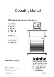
JULABO recirculating coolers have been designed for temperature application to specific fluids in a<br />
bath tank. The units provide pump nozzles for temperature application to an external system (loop<br />
circuit).<br />
The recirculating coolers are operated via the splash-proof keypad. The<br />
implemented microprocessor technology allows to set and to store different values<br />
that can be indicated on the VFD COMFORT-DISPLAY. Three menu keys facilitate<br />
adjusting setpoints, warning and safety functions and menu functions.<br />
The integrated programmer allows storing and running temperature and timedependent<br />
processes.<br />
1x10<br />
ICC<br />
TCF<br />
ATC 3<br />
RS232<br />
Pt100<br />
SMART<br />
PUMP<br />
“ICC - Intelligent Cascade Control“ represents the supreme solution temperature<br />
control. ICC overs perfect temperature control with self-optimizing PID control<br />
parameters.<br />
The TCF - Temperature Control Features allow the user to have access to all<br />
important temperature control parameters. This means: Full control on the control<br />
mode and the chance to manually adjust or adapt control to the specific application.<br />
Absolute Temperature Calibration (ATC3) provides a high temperature stability in<br />
the bath. With the 3-point calibration an offset is adjusted at three temperatures to<br />
ensure an accurate temperature pattern at the selected spot in the bath over the<br />
full temperature range.<br />
Electrical connections:<br />
The serial interface, switchable from RS232 to RS485, allows modern process<br />
technology without additional interface.<br />
Connection for Pt100 external sensor for external temperature measurement and<br />
control.<br />
The electronic module (option) provides 3 further analog connections (alarm input,<br />
standby input, recorder output, programmer input).<br />
The excess temperature protection conforming to IEC 61010-2-010 is a safety<br />
installation independent from the control circuit. This protection can be indicated<br />
and set on the VFD COMFORT-DISPLAY.<br />
The early warning system for low level signals that bath fluid needs to be refilled<br />
before the low level protection conforming to IEC 61010-2-010 causes a complete<br />
shutdown of the main functional elements.<br />
The pump capacity (electronically adjustable via the motor speed) enables to adapt<br />
to varying conditions for internal and external temperature applications.<br />
JULABO recirculating coolers are not conceived for direct temperature application to<br />
food and luxury articles or pharmaceutical and medico-technical products. Direct<br />
temperature application means: Unprotected contact of the object with the bath<br />
medium (bath fluid).<br />
5
<strong>Operating</strong> manual<br />
Operator responsibility – Safety recommendations<br />
The products of JULABO Labortechnik GmbH warrant a safe operation if installation, operation and<br />
maintenance is carried out according to common safety regulations. This section informs you about<br />
potential dangers that may arise from operating the recirculating cooler and also mentions the most<br />
important safety precautions.<br />
Persons:<br />
The operator is responsible for the qualification of the personnel operating the units.<br />
The operator should be constantly informed about the dangers involved with their job activities as well<br />
as preventive actions.<br />
Make sure all persons expected to carry out operation, installation and maintenance of the unit read<br />
and understand the safety information and operating instructions.<br />
When using hazardous materials, the recirculating cooler may only be operated by persons that are<br />
absolutely familiar with these materials and the recirculating cooler. These persons must be fully aware<br />
of possible risks.<br />
If you have any questions concerning the operation of your unit or the information in this manual,<br />
please contact us!<br />
Contact :<br />
JULABO Labortechnik GmbH<br />
77960 Seelbach / Germany<br />
+49 (0) 7823 / 51-0<br />
+49 (0) 7823 / 24 91<br />
info@julabo.de<br />
www.julabo.de<br />
Handling:<br />
You received a product conceived for industrial use. Nevertheless, avoid strikes to the housing,<br />
vibrations, damages to the keypad foil (keys, display) or contamination.<br />
Make sure the product is regularly checked for proper condition. Regularly check (at least every<br />
2 years) the proper condition of the mandatory, warning, prohibition and safety labels.<br />
Take care that the mains supply features a low impedance to avoid any negative affects on the<br />
instrument being operated in the same mains.<br />
This unit is designed for operation in a controlled electromagnetic environment. This means that<br />
transmitting devices (e.g. cellular phones) should not be used in the immediate vicinity.<br />
Magnetic radiation may influence other units with components susceptible to magnetic fields<br />
(e.g. a monitor). We recommend to keep a minimum distance of 1 m.<br />
Permissible ambient temperature: max. 40 °C, min. 5 °C.<br />
Permissible relative air humidity: 50 % (40 °C).<br />
Do not store in an aggressive atmosphere. Protect from contaminations. Do not expose to sunlight.<br />
Operation:<br />
Only qualified personnel is authorized to perform configuration, installation, maintenance and repairs of<br />
the recirculating cooler.<br />
Routine operation can also be carried out by untrained personnel who should however be instructed by<br />
trained personnel. The summarized user guidance (short manual) and the specification table with<br />
information on individual parameters are sufficient for this.<br />
6
Recirculating Cooler<br />
Use:<br />
The bath can be filled with flammable materials. Fire hazard!<br />
There might be chemical dangers depending on the bath medium used.<br />
Observe all warnings for the used materials (bath fluids) and the respective instructions (safety data<br />
sheets).<br />
Insufficient ventilation may result in the formation of explosive mixtures. Only use the unit in well<br />
ventilated areas.<br />
Only use recommended materials (bath fluids). Only use non-acid and non corroding bath fluids.<br />
When using hazardous materials, the user must attach the enclosed safety labels to the front of the<br />
unit so they are well visible:<br />
Warning label W00:<br />
Colours: yellow, black<br />
Mandatory label M018<br />
Colours: blue, white<br />
Semi S1-0701<br />
Table A1-2 #9<br />
Danger area.<br />
Attention! Observe instructions.<br />
(operating manual, safety data sheet)<br />
Carefully read the user information prior to beginning<br />
operation<br />
Scope: EU<br />
Carefully read the user information prior to beginning<br />
operation<br />
Scope: NAFTA<br />
Particular care and attention is necessary because of the wide operating range.<br />
There are thermal dangers: Burn, scald, hot steam, hot parts and surfaces that can be touched.<br />
Warning label W26:<br />
Colours: yellow, black<br />
Hot surface warning.<br />
(The label is put on by JULABO)<br />
Observe the instructions in the manuals for instruments of a different make that you connect to the<br />
recirculating cooler, particularly the respective safety recommendations. Also observe the pin<br />
assignment of plugs and technical specifications of the products.<br />
Disposal:<br />
The recirculating cooler contains a so-called back-up battery that supplies voltage to memory chips<br />
when the unit is switched off. Do not dispose of the battery in domestic waste!<br />
Depending on battery regulations in your country, you might be obliged to give back used or defect<br />
batteries to gathering places.<br />
The product may be used with oil as bath fluid. These oils fully or partially consist of mineral oil or<br />
synthetic oil. For disposal, observe the instructions in the safety data sheets.<br />
This unit contains the refrigerants R404A – at this time considered not to have any negative effects on<br />
the ozone layer. However, during the long operating period of the unit, disposal prescriptions may<br />
change. So only qualified personnel should take care of disposal.<br />
Valid in EU countries<br />
Directive 2002/96/EC of the European Parliament and of the Council of 27 January<br />
2003 on waste electrical and electronic equipment (WEEE).<br />
This directive requires electrical and electronic equipment marked with a crossedout<br />
trash can to be disposed of separately in an environmentally friendly manner.<br />
Contact an authorized waste management company in your country.<br />
Disposal with household waste (unsorted waste) or similar collections of municipal<br />
waste is not permitted!<br />
7
<strong>Operating</strong> manual<br />
EC Declaration of Conformity<br />
Recirculating cooler:<br />
SC 2500a,<br />
SC 2500w<br />
The products mentioned comply with the requirements outlined by the following European<br />
guidelines:<br />
Guideline 73/23/EEC of the Council of 19 February 1973 with respect to legal harmonization of the<br />
member countries concerning electric devices for use within certain voltage<br />
limits<br />
Guideline 89/336/EEC of the Council of 3 May 1989 with respect to legal harmonization of the member<br />
countries concerning electromagnetic compatibility<br />
Guideline 98/37/EC of the European Parliament and the Council of 22 June 1998 for harmonization of<br />
legal and administrative regulations of the member countries with respect to<br />
machinery<br />
Guideline 97/23/EG of the European Parliament and the Council of 29. May 1997 with respect to legal<br />
harmonization of the member countries with respect to pressure equipment.<br />
The units conform to the following standards:<br />
EN 1050: 1996-11 EN 292-1: 1991-09 EN 292-2: 1991-09<br />
EN 61010-1: 2001 EN 61010-2-10: 1994-07 EN 60204-1: 1997-12<br />
EN 563: 1994-06 EN 61326: 1997-04<br />
EN 378-1:2000-09 EN 378-2:2000-09 EN 378-3:2000-09<br />
EN 378-4:2000-09<br />
JULABO Labortechnik GmbH<br />
Eisenbahnstr. 45<br />
77960 Seelbach / Germany<br />
8
Recirculating Cooler<br />
Warranty conditions<br />
JULABO Labortechnik GmbH warrants its products against defects in material or in workmanship,<br />
when used under appropriate conditions and in accordance with appropriate operating instructions<br />
for a period of ONE YEAR.<br />
Extension of the warranty period – free of charge<br />
With the ‘1PLUS warranty’ the user receives a free of charge extension to the warranty of up to 24<br />
months, limited to a maximum of 10 000 working hours.<br />
To apply for this extended warranty the user must register the unit on the JULABO web site<br />
www.julabo.de, indicating the serial no. The extended warranty will apply from the date of JULABO<br />
Labortechnik GmbH’s original invoice.<br />
JULABO Labortechnik GmbH reserves the right to decide the validity of any warranty claim. In case of<br />
faults arising either due to faulty materials or workmanship, parts will be repaired or replaced free of<br />
charge, or a new replacement unit will be supplied.<br />
Any other compensation claims are excluded from this guarantee.<br />
9
<strong>Operating</strong> manual<br />
Technical specifications<br />
Professional Series SC 2500a SC 2500w<br />
Working temperature ranges:<br />
Standard unit °C +5 ... +35 +5 ... +35<br />
Option Low Temp °C -20 ... +35 -20 ... +35<br />
Option Low /HighTemp I °C -20 ... +80 -20 ... +80<br />
Temperature stability °C 0.1 0.1<br />
Absolute Temperature Calibration ±3 ±3<br />
Heater wattage (at 230 V) Option H1 kW 1.0 1.0<br />
Cooling capacity °C +20 0 -10 +20 0 -10<br />
Medium ethanol kW 2.5 1.5 0.9 2.5 1.5 0.9<br />
Refrigerant R404A R404A<br />
Pump capacity P0 (Standard) / P3 * (Option)<br />
see table 1 page 11<br />
Flow rate P0 / P3 L/min at 0 bar 48 / 33 48 / 33<br />
Pressure max. P0 / P3 bar at 0 liter 1.78 / 3.5 1.78 / 3.5<br />
Overall dimensions (WxDxH) cm 49x62/105 49x62/105<br />
Filling volume liters 21 ... 33 21 ... 33<br />
Weight kg 135 122,5<br />
Ambient temperature °C 5 ... 40 5 ... 40<br />
Mains power connection ±10 % V/ Hz 230 / 50 230 / 50<br />
Current consumption without heater A ------- -------<br />
Current consumption with 1kW heater A 14.8 15.1<br />
Mains power connection V/ Hz 208-230/60 208-230/60<br />
Current consumption (at 230 V) without heater A ------- -------<br />
Current consumption (at 230 V) 1kW heater A 14.8 15.1<br />
All measurements have been carried out at: rated voltage and frequency ambient temperature: 20 °C<br />
Technical changes without prior notification reserved.<br />
* Pump P3- reduces cooling capacity by 0.3 kW<br />
10
Recirculating Cooler<br />
Professional series<br />
Temperature selection<br />
digital<br />
via keypad<br />
indication on VFD COMFORT-DISPLAY<br />
remote control via personal computer<br />
indication on monitor<br />
Temperature indication °C VFD COMFORT-DISPLAY<br />
Resolution °C 0.1<br />
Temperature control<br />
ICC - Intelligent Cascade Control<br />
Electrical connections:<br />
Computer interface RS232<br />
External Pt100 sensor<br />
Optional<br />
Programmer input<br />
-100 °C to 400 °C = 0 - 10 V or 0 - 20 mA or 4 - 20 mA<br />
Input for the signal of a flow meter or external manipulated variable<br />
Temperature recorder outputs 0 - 10 V (0 V = -100 °C, 10 V = 400 °C)<br />
0 - 20 mA (0 mA = -100 °C, 20 mA = 400 °C)<br />
4 - 20 mA (4 mA = -100 °C, 20 mA = 400 °C)<br />
Standby input<br />
for external emergency switch-off<br />
Alarm output<br />
for external alarm signal<br />
Table 1<br />
Pump capacity<br />
Bath fluid: Water, Silicone -oil<br />
XX.XX<br />
PUMP<br />
1<br />
XX.XX<br />
PUMP<br />
2<br />
XX.XX<br />
PUMP<br />
3<br />
Circulating pump:<br />
Flow rate max.<br />
Pressure max.<br />
Lpm at 0 bar<br />
bar at 0 liter<br />
P0 P3 P0 P3 P0<br />
31 30 42 33 48<br />
0.75 1.8 1.2 3.5 1.78<br />
Bath fluid: Galden ®<br />
eg. Fluorinert ® 3283<br />
Pressure max. bar at 0 liter<br />
3.5 1,78<br />
Notice:<br />
If Galden ® or Fluorinert ® is used the the charge of the motor increases. Wrong adjustment<br />
causes overheating and eventually destruction of the motor.<br />
With the circulation pump P0 a maximum pump pressure stage >PUMP 2< may be<br />
adjusted.<br />
With the circulation pump P3 a maximum pump pressure stage >PUMP 1< may be<br />
adjusted..<br />
The pump type can be recognized in the order no. on the name plate.<br />
95 xx xxx _ xx PX xx<br />
11
<strong>Operating</strong> manual<br />
Only for water-cooled models:<br />
Cooling water pressure (IN / OUT ) max. 6 bar<br />
Difference pressure (IN - OUT )<br />
3.5 to 6 bar<br />
Cooling water temperature
ESC<br />
130<br />
60<br />
180<br />
30<br />
10 220<br />
°C<br />
ENERGENCY STOP<br />
OFF<br />
ON<br />
Recirculating Cooler<br />
<strong>Operating</strong> instructions<br />
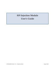
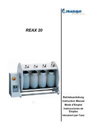
1. <strong>Operating</strong> controls and functional elements<br />
Front view<br />
5 4 3 2 1<br />
Rear view<br />
12 16<br />
T<br />
NOT-AUS<br />
6<br />
7<br />
8<br />
19<br />
22<br />
23<br />
9<br />
SC 2500<br />
21<br />
24<br />
25<br />
10<br />
26<br />
1 Mains power switch<br />
2 Emergency stop switch<br />
3<br />
130<br />
60<br />
180<br />
30<br />
10 220<br />
°C<br />
4 Keypad<br />
Adjustable excess temperature protection according to IEC 61010-2-010<br />
Start / stop key<br />
Key for selecting the working temperature - Setpoint 1, 2, 3<br />
Key for selecting the warning and safety values<br />
MENU button - for selecting the menu functions<br />
Cursor keys<br />
(left or right)<br />
13
<strong>Operating</strong> controls and functional elements<br />
Edit keys<br />
Enter key<br />
(increase or decrease)<br />
1) Store value / parameter<br />
2) Next lower menu level<br />
5<br />
Escape key<br />
1. Cancel entries<br />
2. Return to a higher menu level<br />
VFD COMFORT-DISPLAY<br />
Header: Control indicators see sections 2.1 and 2.2<br />
Line 1: Actual value internal or external<br />
The display is depending on the selected control mode in the<br />
menu > Control < (internal or external).<br />
Line 2: Working temp. setpoint, constantly S xxx.xx<br />
Line 3: Actual value (E = external or I = internal)<br />
Alternating with the display in line 1<br />
XXXXX<br />
S xxxxx<br />
FL GOOD<br />
XXXXX<br />
S xxxxx<br />
R 005<br />
Use the key to indicate further values in line 3. However, the functions of<br />
these keys are different with the programmer started.<br />
PI Capacity in % - with manipulated variable set to >controlSERIALEPROGFLOWRATEGOOD< = Pump switched on<br />
R Resistifity measurement and actual value display in the range from<br />
0.5 ... 5 MOhm/cm<br />
Press to return to actual value (E = external or I = internal)<br />
5.1 Control indicators in the header:<br />
Heating / Cooling / Alarm /<br />
Remote control<br />
5.2 Control indicators in the header:<br />
Temperature indication Internal or External actual value<br />
Temperature indication in °C (°F not possible on this unit)<br />
5.3<br />
Display for the adjusted pump pressure stage.<br />
Adjustable via the<br />
button, in the menu >PUMP
Recirculating Cooler<br />
Rear view<br />
12<br />
RS232<br />
Interface RS232: remote control via personal computer<br />
Option: Electronic module<br />
13<br />
Alarm output (for external alarm signal)<br />
14<br />
15<br />
ALARM<br />
STAND-BY<br />
REG+E-PROG<br />
Standby input (for external emergency switch-off)<br />
Programmer input and temperature recorder output<br />
16<br />
Socket for external measurement and control sensor<br />
or external setpoint programming<br />
ext Pt100<br />
19 2 Connectors for solenoid valve. 230 V / max. 0.1 A<br />
No control voltage in the -OFF- condition<br />
20 2 Safety cutouts: Mains fuses 16 A<br />
0<br />
1<br />
Motor protection circuit breaker for compressor motor<br />
21 Mains power cable with plug<br />
22<br />
23<br />
Pump connectors: 3/4” NPT Feed Return<br />
24 Overflow connector with colar nut<br />
Closable when using e.g. 3M Fluorinert ® as temperature liquid.<br />
25 Drain port with cup nut<br />
Recommendation:<br />
Before filling please install a drain cock at the discharge nozzle.<br />
Connection: ½ " (not included in delivery)<br />
26<br />
OUT IN<br />
Only for water cooled models: Cooling water OUTLET and INLET<br />
15
Safety notes for the user<br />
2. Safety notes for the user<br />
In addition to the safety warnings listed above, warnings are posted throughout the<br />
manual. These warnings are designated by an exclamation mark inside an equilateral<br />
triangle. „Warning of a dangerous situation (Attention ! Please follow the documentation).“<br />
The danger is described according to an alarm keyword.<br />
Read and follow these important instructions.<br />
Warning:<br />
Describes a possibly highly dangerous situation. If this is not avoided, serious injury and<br />
danger to life could result.<br />
Caution:<br />
Describes a possibly dangerous situation. If this is not avoided, slight or minor injuries<br />
could result. A warning of possible damage can also be contained in the text.<br />
Notice:<br />
Describes a possibly harmful situation. If this is not avoided, the product or anything in its<br />
surroundings can be damaged.<br />
3. Preparations<br />
3.1. Installation<br />
• Place the unit in an upright position.<br />
For better stability, apply the holding brakes on the front casters.<br />
• The place of installation should be large enough and provide sufficient<br />
air ventilation to ensure the room does not warm up excessively<br />
because of the heat the instrument radiates to the environment. (Max.<br />
permissible ambient temperature: 40 °C).<br />
With regard to a disturbance in the cooling loop (leakage), the<br />
guideline EN 378 prescribes a certain room space to be available for<br />
each kg of refrigerant.<br />
The necessary amount of refrigerant is specified on the type plate.<br />
> For 0.48 kg of refrigerant R404A, a room space of 1 m 3 is required.<br />
• Keep at least 20 cm of open space on the front and rear venting grids.<br />
• Do not set up the unit in the immediate vicinity of heat sources and do<br />
not expose to sun light<br />
• Before operating the unit after transport, wait about one hour after<br />
setting it up. This will allow any oil that has accumulated laterally<br />
during transport to flow back down thus ensuring maximum cooling<br />
performance of the compressor.<br />
Recommendation:<br />
Before filling please install a drain cock at the discharge nozzle. (25)<br />
Connection: ½ " (not included in delivery)<br />
16
Recirculating Cooler<br />
Only for water cooled models:<br />
Ensure circulation of cooling water by connecting the tubing to cooling<br />
water inlet and outlet on the rear of the recirculating cooler.<br />
Cooling water connectors<br />
G3/4” external thread<br />
Cooling water temperature
Preparations<br />
3.2.1. External control<br />
Pt100<br />
The recirculating cooler is intended for internal and external temperature<br />
control. Switching is carried out in the submenu >Control< (see page 30)<br />
IMPORTANT: Measures for external control<br />
For external control and temperature measurement an external<br />
Pt100 sensor must be connected to the socket (17) on the rear of the<br />
recirculating cooler.<br />
Order No. Description Material cable<br />
8 981 003 200 x 6 mm dia., stainless steel 1.5 m<br />
8 981 005 200 x 6 mm dia., glass 1.5 m<br />
8 981 006 20 x 2 mm dia., stainless steel 1.5 m<br />
8 981 010 300 x 6 mm dia., stainless steel 1.5 m<br />
8 981 013 600 x 6 mm dia., stainless steel/Teflon 3 m<br />
8 981 014 1200 x 6 mm dia., stainless steel/Teflon 3 m<br />
8981103 Extension cable for Pt100 sensor 3.5 m<br />
8 981 020 M+R in-line Pt100 sensor<br />
The M+R in-line Pt100 sensor is a flow sensor and can be installed in<br />
the loop circuit.<br />
Pt100<br />
M+R<br />
3.3. Bath fluids<br />
Caution:<br />
Carefully read the safety data sheet of the bath fluid used, particularly with regard to<br />
the fire point!<br />
If a bath fluid with a fire point of ≤ 65 °C is used, only supervised operation is possible.<br />
Water:<br />
The quality of water depends on local conditions.<br />
Ferrous water can cause corrosion - even on stainless steel.<br />
Chloric water can cause pitting corrosion.<br />
Water/glycol mixture:<br />
Water evaporates and thus the mixture may become flammable. In the heating phase,<br />
a fire may be caused due to the hot surface temperature of the heater.<br />
Fill up water in time and check the mixing ratio in regular intervals (e.g. using an<br />
appropriate device).<br />
Recommended bath fluids:<br />
Bath fluids Temperature range Flash point fire point<br />
water 5 °C ... +80 °C<br />
mixture water/glycol -30 °C ... +50 °C<br />
JULABO Thermal G -30 °C ... +80 °C ---<br />
JULABO Thermal H5S -50 °C ... +105 °C >110 °C >130 °C<br />
18
Bath fluids Temperature range Flash point fire point<br />
JULABO Thermal H10S -20 °C ... +180 °C >175 °C >210 °C<br />
Recirculating Cooler<br />
3M Fluorinerts ®<br />
H-Galden ®<br />
read the safety data sheet<br />
read the safety data sheet<br />
ATTENTION: The maximum permissible viscosity is 30 mm 2 /s .<br />
Order No. 10 liters Bath fluids Order No. 5 liters<br />
8 940 124 Thermal G 8 940 125<br />
8 940 106 Thermal H5S 8 940 107<br />
8 940 114 Thermal H10S 8 940 115<br />
Notice:<br />
Please contact JULABO before using other than recommended bath fluids.<br />
JULABO takes no responsibility for damages caused by the selection of an unsuitable<br />
bath fluid.<br />
Unsuitable bath fluids are liquids which e.g.<br />
• are very highly viscous<br />
(much higher than 30 mm 2 /s at the respective working temperature)<br />
• have corrosive characteristics or<br />
• tend to cracking.<br />
Caution:<br />
The temperature controlling i.e. of fluids in a reactor constitutes normal circulator<br />
practice.<br />
We do not know which substances are contained within these vessels.<br />
Many substances are:<br />
• inflammable, easily ignited or explosive<br />
• hazardous to health<br />
• environmentally unsafe<br />
i.e.: dangerous<br />
The user alone is responsible for the handling of these substances!<br />
The following questions shall help to recognize possible dangers and to reduce the<br />
risks to a minimum.<br />
• Are all tubes and electrical cables connected and installed?<br />
Note:<br />
sharp edges, hot surfaces in operation, moving machine parts, etc.<br />
• Do dangerous steams or gases arise when heating?<br />
Is an exhaust needed when working?<br />
• What to do when a dangerous substance was spilled on or in the unit?<br />
Before starting to work, obtain information concerning the substance and<br />
determine the method of decontamination.<br />
19
Preparations<br />
3.3.1. Tubing<br />
Recommended tubing:<br />
Textile-reinforced tubing<br />
Maximum pressure<br />
> 4.5 bar<br />
Warning: Tubing:<br />
At high working temperatures the tubing used for temperature application and cooling<br />
water supply represents a danger source.<br />
A damaged tubing line may cause hot bath fluid to be pumped out within a short time.<br />
This may result in:<br />
• Burning of skin<br />
• Difficulties in breathing due to hot atmosphere<br />
Safety recommendations<br />
• Employ suitable connecting tubing.<br />
• Make sure that the tubing is securely attached.<br />
• Avoid sharp bends in the tubing, and maintain a sufficient distance from<br />
surrounding walls.<br />
• Regularly check the tubing for material defects (e.g. for cracks).<br />
• Preventive maintenance: Replace the tubing from time to time.<br />
3.4. Filling<br />
Liquid level<br />
• Connect the tubing from the external system to the pump<br />
connectors and check for leaks.<br />
• Check to make sure that the drain tap (25) is closed.<br />
• Remove the cap from the filling opening (9).<br />
• Fill the bath tank using a funnel while monitoring the filling level<br />
(6).<br />
Filling of the external system.<br />
• Turn the mains switch (1) on<br />
• Press the key for filling the cooling loop for the external<br />
system.<br />
Make sure that air can evacuate from the system..<br />
• Check the filling level (6) and keep on filling the bath liquid using<br />
the funnel.<br />
• After having finished the filling process, the liquid level should be<br />
below “MAX”.<br />
• Close the filling opening.<br />
Notice:<br />
Pay attention to the thermal expansion of bath oil during heating to avoid<br />
overflowing of the liquid.<br />
20
Recirculating Cooler<br />
3.5. Draining<br />
• Turn the mains switch (1) off.<br />
• Place a suitable vessel for accepting the used bath liquid<br />
underneath the drain.<br />
• Unscrew the cup nut (A) from the drain port (25) and<br />
empty the unit completely.<br />
A<br />
• Close the drain port.<br />
Notice:<br />
Exercise caution when emptying hot bath fluids!<br />
Check the temperature of the bath fluid prior to draining (by switching the unit on for<br />
a short moment, for example). Store and dispose the used bath fluid according to<br />
the laws for environmental protection.<br />
21
<strong>Operating</strong> procedures<br />
4. <strong>Operating</strong> procedures<br />
4.1. Power connection<br />
Caution:<br />
Only connect the unit to a power socket with earthing contact (PE – protective earth)!<br />
We disclaim all liability for damage caused by incorrect line voltages!<br />
Check to make sure that the line voltage matches the supply voltage<br />
specified on the identification plate. Deviations of ±10 % are permissible.<br />
4.2. Switching on / Start - Stop<br />
Switching on:<br />
• Turn on the mains power switch (1).<br />
During the self-test all segments of the VFD-Info-Display light up.<br />
Then the software version number (example: V 4x.1x) and the order<br />
number of the recirculating cooler appears.<br />
(Example: [ 95 20 025 03 P0H1 ] ).<br />
The display „OFF“ or „R OFF“ indicates the unit is ready to operate.<br />
-OFF-<br />
S 150.0<br />
I 24.6<br />
XXXXX<br />
95xxxxx<br />
-xxPxHx<br />
The recirculating cooler enters the operating mode activated before<br />
switching the recirculating cooler off:<br />
keypad control mode (manual operation)<br />
or<br />
remote control mode (operation via personal computer).<br />
Start: Press the start/stop key .<br />
The actual bath temperature is displayed on the VFD COMFORT-<br />
DISPLAY.<br />
Stop: Press the start/stop key .<br />
The VFD COMFORT-DISPLAY indicates the message „OFF“.<br />
Autostart: see chapter 7.3.2.<br />
A-START – Autostart<br />
The Autostart function enables the start of the recirculating cooler<br />
directly by pressing the mains switch or using a timer.<br />
22
Recirculating Cooler<br />
5. Setting the temperatures<br />
Factory settings:<br />
SETP 1 25 °C<br />
SETP 2 37 °C<br />
SETP 3 70 °C<br />
Press the key to call up the menu for temperature selection.<br />
3 different working temperatures are adjustable. Their values are freely<br />
selectable within the operating temperature range.<br />
This setting may be carried out with the recirculating cooler being in the<br />
Start or Stop condition!<br />
Example: Setting working temperature "SETPoint 3"<br />
XXXXX<br />
SETP 3<br />
70.0<br />
XXXXX<br />
SETP 3<br />
85.0<br />
1. Press the key until the desired menu window is indicated on the<br />
VFD COMFORT-DISPLAY<br />
Example: SETP 3 / 70.0 °C (last digit blinks)<br />
2. Change the value to 85 °C.<br />
Use the cursor keys to move left or right on the display until the<br />
numeral you wish to change blinks.<br />
Use the increase/decrease arrows<br />
numeral (-, 0, 1, 2, 3, ... 9).<br />
see example left: SETP 3 / 85.0.<br />
to change the selected<br />
3. Press enter to store the value.<br />
In the >Start< condition this value is immediately used for controlling the<br />
working temperature.<br />
The indication on the VFD COMFORT-DISPLAY is updated.<br />
The heater control indicator blinks.<br />
<br />
Notice: See SETMAX and SETMIN in chapter 7.5.<br />
Example: Selecting the working temperature<br />
MENU LIMITS<br />
SETP 1<br />
SETP 2<br />
SETP 3<br />
1. Press the key until the desired menu item is indicated on the VFD<br />
COMFORT-DISPLAY.<br />
2. Press enter .<br />
The recirculating cooler uses the new working temperature value for<br />
temperature control.<br />
23
Safety installations, warning functions<br />
6. Safety installations, warning functions<br />
Settings for the excess temperature protection > SAFETMP< according to<br />
IEC 61010-2-010 and for the high > OVERTMP< and low> SUBTMP<<br />
temperature warning functions are made in a menu that is called up with the<br />
‣ SAFETMP<br />
‣ OVERTMP<br />
‣ SUBTMP<br />
‣ LIMITSR<br />
key .<br />
Menu item > LIMITSR OVERTMP< and >SUBTMP< choose between a<br />
warning message being signalled or a complete shutdown of the main<br />
functional elements such as heater and circulating pump being effected.<br />
6.1. Excess temperature protection<br />
This safety installation is independent of the control circuit. When the<br />
temperature of the bath fluid has reached the safety temperature, a<br />
complete shutdown of the heater and pump is effected.<br />
XXXXX<br />
ALARM<br />
CODE 1<br />
The alarm is indicated by optical and audible signals (continuous tone)<br />
and on the VFD COMFORT-DISPLAY appears the error message<br />
"ALARM-CODE 1".<br />
Setting range: 20 °C ... 220 °C<br />
XXX.X<br />
SAFETMP<br />
100<br />
80<br />
40<br />
0<br />
160<br />
240<br />
320<br />
°C°C<br />
1. Press the button until the menu item > SAFETMP < is<br />
displayed.<br />
2. Set the new cut-out value using a screwdriver via the VFD<br />
COMFORT-DISPLAY (Example: 100 °C)<br />
3. Press to update the display immediately, or the unit<br />
automatically returns to the effective display after<br />
about 30 seconds .<br />
Recommendation:<br />
Set the excess temperature protection at 5 to 10 °C above the working<br />
temperature setpoint.<br />
Warning:<br />
The excess temperature protection >SafeTemp< should be set at least 25 °C below<br />
the fire point of the bath fluid used.<br />
In the event of wrong setting there is a fire hazard!<br />
We disclaim all liability for damage caused by wrong settings!<br />
24
Recirculating Cooler<br />
6.1.1. Early warning system, low level protection<br />
(patented)<br />
This low level protection is independent of the control circuit and is<br />
divided in two sections.<br />
1. Switch in stage 1 recognizes a critical fluid level .<br />
An audible warning (interval tone) sounds and a message<br />
appears on the VFD COMFORT-DISPLAY.<br />
XXXXX<br />
WARNING<br />
CODE 40<br />
Refill bath fluid!<br />
2. Switch in stage 2 recognizes a low fluid level .<br />
If stage 2 of the low level protection device (according to<br />
IEC 61010-2-010) is triggered, a complete shutdown of<br />
the heater and circulating pump is effected.<br />
A continuous alarm tone sounds and a message<br />
>ALARM< >CODE 01< appears on the VFD COMFORT-<br />
DISPLAY.<br />
XXXXX<br />
ALARM<br />
CODE 1<br />
Turn off the unit with the mains switch, refill bath fluid and<br />
turn the unit on again!<br />
Important: Check the safety installations from time to time.<br />
See page 61<br />
Warning:<br />
For refill always use the same bath fluid type that is already in the bath.<br />
Bath oils must not contain any water contaminants and should be pre-heated to the<br />
actual bath temperature! Explosion hazard at higher temperatures!<br />
25
Safety installations, warning functions<br />
6.2. Over and Sub temperature warning functions<br />
Over temperature<br />
Sub temperature<br />
XXXXX<br />
SUBTMP<br />
-94.9<br />
If for a sensitive temperature application task adherence to a working<br />
temperature value > SETP < is to be supervised, then set over and sub<br />
temperature warning values.<br />
In the example below, the > SETP < of 85 °C is surrounded by the values<br />
> OVERTEMP < 87 °C and > SUBTEMP < 83 °C. The electronics<br />
immediately registers when the actual temperature attains a temperature out<br />
of the limits and it follows a reaction according to what is set in the menu<br />
item >LIMITSR OVERTMP < or<br />
>SUBTMP< is displayed.<br />
2. Set value:<br />
Use the cursor keys to move left or right on the display until the<br />
numeral you wish to change blinks.<br />
Use the increase/decrease arrows<br />
numeral (-, 0, 1, 2, 3, ... 9).<br />
to change the selected<br />
3. Press enter to store the value.<br />
The warning functions are only triggered when the actual bath<br />
temperature, after start from the „OFF“ or „rOFF“ mode, lies within the<br />
set limits for 3 seconds.<br />
Recommendation:<br />
Set the high temperature warning value > OVERTMP < at 5 °C to 10 °C<br />
above the working temperature setpoint.<br />
Set the low temperature warning value > SUBTMP < at 5 °C to 10 °C below<br />
the working temperature setpoint.<br />
26
Recirculating Cooler<br />
6.2.1. Change-over of the warning function to shutdown function<br />
For the two menu items > OVERTMP< and >SUBTMP< choose between a<br />
warning message being signalled or a complete shutdown of the main<br />
functional elements such as heater and circulating pump being effected (see<br />
page 26).<br />
• Setting >WARNING<<br />
An audible warning (interval tone) sounds and a meassage appears on<br />
the VFD COMFORT-DISPLAY.<br />
Factory setting:<br />
>WARNING<<br />
<br />
XXXXX<br />
WARNING<br />
CODE 03<br />
OVERTMP<br />
or<br />
XXXXX<br />
WARNING<br />
CODE 04<br />
SUBTMP<br />
• Setting >ALARM<<br />
A complete shutdown of heater and circulating pump is effected.<br />
An audible alarm (continuous tone) sounds and a message appears on<br />
the VFD COMFORT-DISPLAY.<br />
XXXXX<br />
ALARM<br />
CODE 03<br />
OVERTMP<br />
oer<br />
XXXXX<br />
ALARM<br />
CODE 04<br />
SUBTMP<br />
1. Press the button until the menu item >LIMITSR< is displayed.<br />
2. Select the parameter with the keys .<br />
(>WARNING< or >ALARM
Menu functions<br />
7. Menu functions<br />
The term „menu functions“ refers to adjustments such as<br />
‣ PUMP Electronically adjustable pump capacity page 29<br />
‣ CONTROL Intelligent Cascade Control, control parameters page 30<br />
CONTROL - internal or external control<br />
ELFTUNING<br />
DYNAMIC - internal<br />
COSPEED - external<br />
Control parameters - XP, TN, TV internal<br />
Control parameters - XP, TN, TV, XPU external<br />
‣ CONFIG Configurationen of the unit page 36<br />
SET (Setpoint) – keypad control or remote control<br />
A-START – Autostart<br />
OFF MODE – Motor on / off<br />
RESET – Factory settings<br />
ACTVAR – actuating variable<br />
TIME / DATE – Setting time and date<br />
‣ SERIAL Adjustable interface parameters page 42<br />
BAUDRAT, H-SHAKE, PARITY<br />
(Baud rate, Handshake, Parity)<br />
‣ LIMITS Limits to temperature or capacity page 43<br />
SET MAX / MIN - Maximum and minimum setpoint<br />
HEAT MAX - Adjusted maximum heating<br />
COOL MAX - Adjusted maximum cooling<br />
INTERN MAX / MIN – Limitation of the working temperature range<br />
BAND HIGH / LOW – Band limit<br />
‣ PROGRAM Integrated programmer page 45<br />
‣ ADJUST ATC - Absolute Temperature Calibration, page 49<br />
Sensor calibration, 3-point calibration<br />
‣ ANALOG<br />
Indication only when<br />
the Analog Interface<br />
Modul is mounted.<br />
Analog inputs/outputs page 53<br />
F-ALARM – Function at Alarm<br />
A-ALARM – Type of Alarm<br />
EX-STBY - STAND-BY input<br />
CHANNEL – Output 1, 2, 3<br />
EPROG – External programmer input<br />
28
Recirculating Cooler<br />
• Menu level 1:<br />
Example:<br />
Menu level 1<br />
Continue: Press<br />
to quit the menu.<br />
Press the button to scroll in menu level 1.<br />
If the desired (‣) menu item is indicated on the VFD COMFORT-<br />
DISPLAY, press enter to change to menu level 2.<br />
• Menu level 2:<br />
Press the button to scroll in the selected menu item, line 3 of the<br />
display blinks.<br />
If a value is set or a parameter selected, press enter to confirm.<br />
Each input can be cancelled with the<br />
the next higher menu level.<br />
. The cursor then returns to<br />
Legend:<br />
Continue: Press<br />
/ or<br />
The display remains visible for approx. 30 seconds<br />
within this period,<br />
or press the button to scroll in the menu level<br />
or press to return to the next higher menu level.<br />
. Start to set a value<br />
7.1. MENU PUMP - Setting the pump pressure<br />
The pressure of the circulating pump is adjustable in stages. After setting,<br />
the VFD COMFORT-DISPLAY indicates the corresponding value.<br />
Adjustable pump capacity stage 1 ... 3<br />
Examples:<br />
Illuminated display: for pump pressure<br />
Display for the adjusted pump pressure stage.<br />
XXX.X<br />
PUMP<br />
2<br />
1. Press the button until the menu item > MENU / PUMP < is<br />
displayed.<br />
2. Press enter to indicate the parameter.<br />
3. Select the parameter with the keys (1 ... 3).<br />
4. Press enter to store the selected parameter.<br />
Continue: Press or .<br />
Notice:<br />
Pump capacity: See Table 1 page 11<br />
29
Menu functions<br />
7.2. MENU CONTROL – Control parameters<br />
CONTROL: Press enter to switch to menu level 2<br />
>CONTROL< (INT / EXT )<br />
>SELFTUN<<br />
>DYNINT<<br />
(ALWAYS / OFF / ONCE)<br />
(APER / NORM)<br />
>XP INT< (0.1 ... 99.9)<br />
>TN INT< (3 ... 9999)<br />
or<br />
>TV INT< (0 ... 999)<br />
>CONTROL<<br />
>SELFTUN<<br />
( INT / EXT)<br />
(ALWAYS / OFF / ONCE)<br />
>COSPEED< (0 ... 5)<br />
>XP EXT< (0.1 ... 99.9)<br />
>TN EXT< (3 ... 9999)<br />
> TV EXT (0 ... 999)<br />
>XPU EXT< (0.1 ... 99.9)<br />
7.2.1. CONTROL – internal / external control<br />
The recirculating cooler is conceived for internal and external<br />
temperature control. Switching is carried out in this submenu.<br />
Depending on what is set, only the respective set of parameters is<br />
indicated.<br />
Factory setting:<br />
INT<br />
Possible parameters:<br />
INT internal temperature control<br />
EXT external temperature control with external Pt100 sensor<br />
The control type can only be adjusted in the -OFF- condition<br />
1. Press the button until the submenu >CONTROL< is displayed.<br />
2. Select the parameter with the keys (INT / EXT).<br />
3. Press enter to store the selected parameter.<br />
Continue: Press<br />
or<br />
30
Recirculating Cooler<br />
Pt100<br />
IMPORTANT:<br />
Additional measures for external temperature control.<br />
Connect a Pt100 sensor to the socket on the rear of the recirculating cooler.<br />
Suggested adjustments for external temperature control:<br />
BAND HIGH / LOW and INTERN MAX / MIN<br />
see chapter > LIMITS < on page 43.<br />
Sensor calibration of the external Pt100 sensor is carried out in the >MENU /<br />
ADJUSTATC SEN / EXT< (see page 49).<br />
Notice:<br />
Place the external sensor into the bath medium and securely fix the sensor.<br />
7.2.2. SELFTUNING<br />
XXXXX<br />
SELFTUN<br />
ALWAYS<br />
Factory setting:<br />
ONCE<br />
Selftuning:<br />
When performing a selftuning for the controlled system (temperature<br />
application system), the control parameters Xp, Tn and Tv are<br />
automatically determined and stored.<br />
Possible parameters:<br />
OFF - no selftuning<br />
The control parameters ascertained during the last identification are<br />
used for control purposes.<br />
ONCE - single selftuning (factory setting)<br />
The instrument performs a single selftuning of the controlled system<br />
after each start with the start/stop key or after receiving a start<br />
command via the interface.<br />
ALWAYS - continual selftuning<br />
The instrument performs a selftuning of the controlled system<br />
whenever a new setpoint is to be reached.<br />
Use this setting only when the temperature application system<br />
changes permanently.<br />
1. Press the button until the submenu > SELFTUN < is displayed.<br />
2. Select the parameter with the keys .<br />
(ALWAYS / OFF / ONCE)<br />
3. Press enter to store the selected parameter.<br />
Continue: Press<br />
or<br />
31
Menu functions<br />
7.2.3. DYN INT - Dynamic internal<br />
This parameter affects the temperature pattern only in<br />
case of internal control.<br />
Factory setting: APER (aperiodic)<br />
NORM<br />
°C<br />
temp. stability<br />
APER<br />
Setpoint<br />
NORM<br />
°C<br />
temp. stability<br />
APER<br />
temperature ramp<br />
t<br />
t<br />
Possible parameters:<br />
NORM<br />
Allows for reaching the setpoint faster, but<br />
overshooting of up to 5 % is possible.<br />
APER Target temperature is attained without<br />
overshooting.<br />
With both adjustments an adequate temperature<br />
stability is reached after approximately the same time.<br />
1. Press the button until the submenu > DYN INT < is displayed.<br />
2. Select the parameter with the keys .<br />
(NORM / APER)<br />
3. Press enter to store the selected parameter.<br />
Continue: Press<br />
or<br />
7.2.4. Control parameters – XP, TN, TV internal<br />
The control parameters preset in factory are in most cases adequate for<br />
achieving an optimum temperature pattern for the samples requiring<br />
temperature application.<br />
Each parameter may be manually set via the keypad if necessary, to<br />
allow optimum control performance.<br />
Proportional range >Xp<<br />
The proportional range is the range below the selected temperature value<br />
in which the control circuit reduces the heating power from 100 % to 0 %.<br />
Setting range:0.1 ... 99.9<br />
Setting range:1 ...9999<br />
Resetting time >Tn< (Integral component)<br />
Compensation of the remaining control deviation due to proportional<br />
regulation. An insufficient resetting time may cause instabilities to occur.<br />
Excessive resetting time will unnecessarily prolong compensation of the<br />
control difference.<br />
32
Recirculating Cooler<br />
Setting range: 0 ... 999<br />
Lead time >Tv< (Differential component)<br />
The differential component reduces the control settling time. An<br />
insufficient lead time will prolong the time required to compensate for<br />
disturbance effects and cause high overshooting during run-up. An<br />
excessive lead time could cause instabilities (oscillations) to occur.<br />
1. Press the button until the desired submenu is displayed -<br />
XP INT, TN INT, TV INT.<br />
2. Set value:<br />
Use the cursor keys to move left or right on the display until<br />
the numeral you wish to change blinks.<br />
Use the increase/decrease arrows<br />
numeral (-, 0, 1, 2, 3, ... 9).<br />
to change the selected<br />
3. Press enter to store the value.<br />
Continue: Press / or<br />
Optimization instructions for the PID control parameters:<br />
°C<br />
optimum setting<br />
The heat-up curve reveals inappropriate control<br />
settings.<br />
t<br />
Inappropriate settings may produce the following heat-up curves:<br />
Xp too low<br />
Tv/Tn too low<br />
°C<br />
°C<br />
°C<br />
t<br />
Xp too high or Tv too high<br />
°C<br />
t<br />
Tv/Tn too high or Xp too high<br />
t<br />
t<br />
33
Menu functions<br />
7.2.5. COSPEED - external<br />
This parameter affects the temperature pattern only in case of external<br />
control.<br />
Possible parameters: 0.0 ... 5.0<br />
1. Press the button until the submenu > COSPEED < is<br />
displayed.<br />
2. Set value:<br />
Use the cursor keys to move left or right on the display until<br />
the numeral you wish to change blinks.<br />
Use the increase/decrease arrows<br />
numeral (-, 0, 1, 2, 3, ... 9).<br />
to change the selected<br />
3. Press enter to store the value.<br />
Continue: Press / or<br />
°C<br />
During selftuning, the control parameters Xp, Tn and Tv of a controlled<br />
system are automatically determined and stored. Depending on the<br />
controlled system, time for tuning can be unequally longer. This<br />
controller layout allows protection of sensitive objects requiring<br />
temperature application.<br />
5<br />
3<br />
Int. temperature<br />
Ext. temperature<br />
0<br />
Setpoint<br />
As soon as a co-speed factor is set, it is<br />
considered for calculating the control<br />
parameters. As shown in the diagram,<br />
tuning times become shorter the higher the<br />
co-speed factor is, but overshooting can<br />
happen in the internal system.<br />
t<br />
34
Recirculating Cooler<br />
7.2.6. Control parameters – XPU, XP, TN, TV external<br />
The control parameters preset in factory are in most cases adequate for<br />
achieving an optimum temperature pattern for the samples requiring<br />
temperature application.<br />
Each parameter may be manually set via the keypad if necessary, to<br />
allow optimum control performance.<br />
Setting range: 0.1 ... 99.9<br />
Setting range: 1 ...9999<br />
Setting range: 0 ... 999<br />
Setting range: 0.1 ... 99.9<br />
1. Press the button until the desired submenu is displayed -<br />
XP EXT, TN EXT, TV EXT, XPU EXT.<br />
2. Set value:<br />
• Use the cursor keys to move left or right on the display<br />
until the numeral you wish to change blinks.<br />
• Use the increase/decrease arrows to change the<br />
selected numeral (-, 0, 1, 2, 3, ... 9).<br />
3. Press enter to store the value.<br />
Continue: Press / or<br />
Proportional range >Xpu<<br />
The proportional range Xpu of the cascaded controller is only needed for<br />
external control.<br />
35
Menu functions<br />
7.3. MENU CONFIG - configuration<br />
CONFIG: Press enter to switch to menu level 2<br />
>SETP< (KEY / SERIAL / PT100 / EPROG*)<br />
Keypad control or remote control<br />
>A-START<<br />
Autostart on / off<br />
>OFFMODE<<br />
Motor on / off<br />
>RESET<<br />
(OFF / ON)<br />
(PMP OFF / PMP ON)<br />
( NO / YES ) Factory settings<br />
>ACTVAR< (CONTROL / SERIAL / EPROG* )<br />
ACTuating VARiable<br />
>TIME<<br />
(hh : mm ) Setting time<br />
>DATE<<br />
(TT/MM.JJ ) Setting date<br />
EPROG* Indication only when electronic module is mounted.<br />
36
Recirculating Cooler<br />
7.3.1. SETPOINT – Keypad control or remote control<br />
The recirculating cooler provides four possibilities for setpoint setting.<br />
1. Press the button until the submenu > SETP < is displayed.<br />
2. Select the parameter with the keys<br />
(KEY / SERIAL / PT100 / EPROG)<br />
3. Press enter to store the selected parameter.<br />
Continue: Press / or<br />
KEY – Setpoint setting with the keys and<br />
or the integrated programmer.<br />
S XX.XX<br />
I XX.XX KEY<br />
-OFF-<br />
S XX.XX SERIAL<br />
I XX.XX<br />
PT100 - Setpoint setting via the analog socket „ext. Pt100“ using an<br />
-OFFexternal<br />
temperature sensor or an appropriate voltage/current<br />
ST XX.XX<br />
I XX.XX<br />
PT100 source.<br />
-OFF-<br />
SP XX.XX<br />
I XX.XX EPROG<br />
Factory setting: KEY<br />
The selected mode is<br />
indicated on the VFD<br />
COMFORT-DISPLAY<br />
-OFF-<br />
SERIAL - Setpoint setting via the serial RS232 interface through a PC<br />
or superordinated data system.<br />
Important:<br />
Connect the recirculating cooler to a PC using an interface<br />
cable.<br />
Check the interface parameters of both interfaces (on<br />
recirculating cooler and PC) and make sure they match.<br />
(see chapter 11.1. Setup for remote control page 64)<br />
EPROG - Can only be adjusted when an electronic module with analog<br />
connections is used (option).<br />
Setpoint setting via the analog interface REG+E-PROG connection<br />
with an external voltage or current source or a programmer.<br />
Important:<br />
Connect the external voltage or current source or a programmer to<br />
the circulator via the socket REG+E-PROG (see page 56).<br />
In the menu >MENU ANALOG< set the parameter >EPROG< and<br />
the input variables (see page 57).<br />
The E-Prog input can only be used either under menu item > SETP<br />
< or under menu item > ACTVAR <<br />
(see page 40).<br />
37
Menu functions<br />
7.3.2. A-START – Autostart<br />
XXXXX<br />
A-START<br />
OFF<br />
Factory setting: OFF<br />
The AUTOSTART function (automatic start mode) is allowing the start of<br />
the instrument directly by pressing the mains power switch or using a<br />
timer.<br />
1. Press the button until the submenu > A-START < is displayed.<br />
2. Select the parameter with the keys (OFF / ON).<br />
3. Press enter to store the selected parameter.<br />
Continue: Press / or<br />
Possible parameters:<br />
ON - AUTOSTART on<br />
OFF - AUTOSTART off<br />
Note:<br />
The temperature system has been configured and supplied by JULABO<br />
according to N.A.M.U.R. recommendations. This means for the start<br />
mode, that the unit must enter a safe operating state after a power failure<br />
(non-automatic start mode). This safe operating state is indicated by<br />
OFF, resp. R OFF on the VFD COMFORT-DISPLAY. A complete<br />
shutdown of the main functional elements such as heater and circulating<br />
pump is effected simultaneously.<br />
The values set on the recirculating cooler remain stored, and the unit is<br />
returned to operation by pressing the start/stop key (in manual control<br />
mode).<br />
In remote control mode, the values need to be resent by the PC via the<br />
interface.<br />
Should such a safety standard not be required, the AUTOSTART<br />
function (automatic start mode) may be activated, thus allowing the start<br />
of the instrument directly by pressing the mains power switch or using a<br />
timer.<br />
The AUTOSTART function can only be used, if setpoint setting is carried<br />
out via > KEY EPROG < or >PT100
Recirculating Cooler<br />
7.3.3. OFF-MODE – Pump motor on / off<br />
XXXXX<br />
OFFMODE<br />
PMP OFF<br />
Factory setting:<br />
PMP OFF<br />
Normally the circulating pump is switched via the start/stop signal.<br />
However, if circulation should be maintained also for the -OFF- condition,<br />
the parameter >PMP ON< needs to be set.<br />
Possible parameters:<br />
PMP ON Pump motor on<br />
PMP OFF Pump motor off<br />
1. Press the button until the submenu > OFFMOD < is displayed.<br />
2. Select the parameter with the keys .<br />
(PMP ON / PMP OFF)<br />
3. Press enter to store the selected parameter.<br />
Continue: Press / or<br />
In case of an alarm state, a shutdown of the pump motor is still<br />
effected.<br />
7.3.4. RESET – Factory settings<br />
Use this to reset all values to factory setting (except date and time).<br />
A RESET can only be carried out in the -OFF- condition.<br />
Factory setting:<br />
NO<br />
Possible parameters:<br />
NO / YES<br />
1. Press the button until the submenu > RESET < is displayed.<br />
2. Select the parameter with the keys (NO / YES).<br />
3. Press enter to store the selected parameter.<br />
As long as the message -RUN- appears all parameters a reset to<br />
factory settings.<br />
39
Menu functions<br />
7.3.5. ACTVAR - actuating variable<br />
XXXXX<br />
ACTVAR<br />
CONTROL<br />
Factory setting:<br />
CONTROL<br />
The variable (ACTuating VARiable) corresponds to the extent to which<br />
the heater or cooling machine of the recirculating cooler is controlled.<br />
Heat or cold is applied to the bath according to this variable. If this<br />
happens with the control electronics of the recirculating cooler, called<br />
> CONTROL < in this particular case, the bath temperature is exactly<br />
heated and maintained constant at the adjusted setpoint.<br />
Programming of variables for the parameters > SERIAL < or ><br />
EPROG < is only accepted, if the unit is in Start mode.<br />
1. Press the button until the submenu > ACTVAR < is displayed.<br />
2. Select the parameter with the keys<br />
(CONTROL / SERIAL / EPROG )<br />
3. Press enter to store the selected parameter<br />
Continue: Press / or<br />
XXXXX<br />
ACTVAR<br />
SERIAL<br />
XXXXX<br />
ACTVAR<br />
EPROG<br />
Possible parameters:<br />
CONTROL – The internal control electronics of the recirculating cooler<br />
controls the heater and cooling machine. Self-tuning is possible.<br />
SERIAL – The heater or cooling machine receives the control signal via<br />
the serial interface. Self-tuning is not possible.<br />
EPROG - The heater or cooling machine receives the control signal via<br />
the E-Prog input. Self-tuning is not possible.<br />
Important:<br />
Under >MENU ANALOG< set the input variable to<br />
>EPROG x / ACTVAR< (see page 57).<br />
XXXXX<br />
EPROG U<br />
ACTVAR<br />
Example: EPROG U / ACTVAR<br />
Note:<br />
The E-Prog input can only be used either under menu item<br />
> SETP < (page 37) or under menu item > ACTVAR
Recirculating Cooler<br />
Warning:<br />
The working temperature range of the recirculating cooler is determined during<br />
configuration. If set to >CONTROL SERIAL < and > EPROG TIME < or > DATE < is<br />
displayed.<br />
2. Setting time / date:<br />
Use the cursor keys to move left or right on the display until<br />
the numeral you wish to change blinks.<br />
Use the increase/decrease arrows<br />
numeral (-, 0, 1, 2, 3, ... 9).<br />
3. Press enter to store the value.<br />
to change the selected<br />
Continue: Press / or<br />
Clock: Only hours and minutes are set.<br />
Settings are checked for plausibility.<br />
41
Menu functions<br />
7.4. MENU SERIAL - BAUDRATE, HANDSHAKE, PARITY<br />
XXXXX<br />
MENU<br />
SERIAL<br />
SERIAL: Press enter to switch to menu level 2<br />
>BAUDRAT<<br />
Factory settings:<br />
4800 Bauds<br />
even<br />
hardware handshake<br />
>PARITY<<br />
>H-SHAKE<<br />
For communication between recirculating cooler and a PC or a<br />
superordinated process system the interface parameters of bath units<br />
must be identical.<br />
1. Press the button until the desired menu item is displayed.<br />
2. Select the parameter with the keys .<br />
3. Press enter to store the selected parameter.<br />
Continue: Press / or<br />
Adjustable interface parameters<br />
BAUDRATE 4800 bauds<br />
9600 bauds<br />
PARITY<br />
no<br />
odd<br />
even<br />
HANDSHAKE<br />
SOFT =<br />
HARD =<br />
software handshake<br />
hardware handshake<br />
Data bits = 7; Stop bits = 1<br />
42
Recirculating Cooler<br />
7.5. MENU LIMITS<br />
XXXXX<br />
MENU<br />
LIMITS<br />
LIMITS: Press enter to switch to menu level 2<br />
>SET MAX<<br />
>SET MIN<<br />
>HEATMAX<<br />
>COOLMAX<<br />
>INT MAX<<br />
>INT MIN<<br />
>BAND H<<br />
In case of external control<br />
these menu items are<br />
additionally indicated.<br />
>BAND L<<br />
1. Press the button until the desired submenu is displayed<br />
2. Set value:<br />
Use the cursor keys to move left or right on the display until<br />
the numeral you wish to change blinks.<br />
Use the increase/decrease arrows<br />
numeral (-, 0, 1, 2, 3, ... 9).<br />
to change the selected<br />
3. Press enter to store the value.<br />
Continue: Press / or<br />
Factory settings<br />
XXXXX<br />
SET MAX<br />
300.00<br />
XXXXX<br />
SET MIN<br />
-94.99<br />
SETPOINT MAX / MIN - Maximum and minimum setpoint<br />
Restriction for the adjustable temperature range.<br />
The limitation of the operating temperature range effects the temperature<br />
setting under the menu called up with the key.<br />
It is possible to adjust only working temperatures that lie within the limit<br />
range set here.<br />
Existing settings for SETP 1, 2, 3 and also for >OVERTEMP< and<br />
>SUBTEMP< (see page 26) are automatically defered within the limit<br />
range.<br />
Setting range:: -94.99 °C ... +300.0 °C<br />
43
Menu functions<br />
Factory settings<br />
Adjusted maximum heating / cooling.<br />
Heating and cooling powers of the recirculating cooler are adjustable.<br />
100 % corresponds to the values in the technical specifications of the<br />
equipment.<br />
Setting range:<br />
HEAT MAX – 0 to 100 % in steps of 1 %<br />
COOLING MAX – 0 to 100 % in steps of 1 %<br />
INTERNAL MAX / MIN<br />
Limit setting<br />
Factory settings<br />
XXXXX<br />
INT MAX<br />
300.00<br />
XXXXX<br />
INT MIN<br />
-94.99<br />
> SAFETMP <<br />
Setting range: -94.9 °C ... +300.0 °C<br />
The limits INT MAX and INT MIN are only valid for external control. INT<br />
MAX and INT MIN are used to limit the expected internal bath<br />
temperatures to any upper and lower values. The temperature controller<br />
cannot exceed these limits even if it would be required for reaching the<br />
temperature in the external system. Consequently the external setpoint<br />
may thus not be reached.<br />
Sense of a limit setting:<br />
Protects the bath fluid from overheating.<br />
Prevents an undesired alarm shutdown by the excess temperature<br />
protection - >ALARM CODE 14INTMAX:< to a value at least 5 °C below the >SAFETEMP:<<br />
value.<br />
Protects the pump motor from high viscosity of the bath fluid at low<br />
temperatures.<br />
For recirculating coolers: Freezing protection when using water as<br />
bath fluid.<br />
BAND HIGH / LOW - Band limit<br />
Factory settings:<br />
For the heat-up and cool-down phases different settings to conform to<br />
the requirements of the particular application are possible.<br />
Setting range: 0 ... 200 °C<br />
Using BAND HIGH and BAND LOW, the difference between the<br />
temperatures in the internal bath and the external system can be limited<br />
to any maximum value for the heat-up or the cool-down phase.<br />
During the heat-up phase the difference value always adds to the actual<br />
external temperature. During the cool-down phase, the difference value<br />
is subtracted.<br />
44
°C<br />
200<br />
150<br />
100<br />
75<br />
50<br />
25<br />
Internal bath<br />
external system<br />
BAND HIGH<br />
BAND LOW<br />
Recirculating Cooler<br />
Sense of a band limit:<br />
Ensures gentle heating for the<br />
objects requiring temperature<br />
application.<br />
Protects glass reactors, for<br />
example, from thermal shock.<br />
The INTMAX: and INTMIN: values are<br />
superordinated to this band limit.<br />
10 20 30 40 50 60 10 20 30 40 50 60 10 [min]<br />
t<br />
7.6. MENU PROGRAM – Integrated programmer<br />
XXXXX<br />
MENU<br />
PROGRAM<br />
PROGRAM: Press enter to switch to menu level 2<br />
>PS STEP< Program start at section ....<br />
1 Profil<br />
10 Sections (STEP)<br />
99 Repetitions<br />
> PS RUNS < Number of profile repetitions 1 ... 99<br />
> PS GO < Start type (NOW/TIME)<br />
> P TIME < Start time (hh:mm)<br />
>P DATE< Start date (TT/MM.JJ)<br />
>PS END< Status at the end of the profile (STBY/SETP)<br />
(Standby or last setpoint)<br />
> PE STEP< Edit profile (1 ... 10)<br />
>Px SEP < Target temperature of section ...<br />
>Px TIM< Time period of section ...<br />
>Px DEL<<br />
Delete a section (STEP) (YES/NO)<br />
> PE DEL< Delete a profile (YES/NO)<br />
The integrated programmer allows any desired temperature program<br />
sequences to be realized. Such a temperature sequence is called profile. A<br />
profile consists of individual sections defined by duration (t:) and target<br />
temperature. Target temperature is the setpoint (T:), that is achieved at the<br />
end of a section. The programmer uses time and temperature difference<br />
values within a section to calculate a temperature ramp.<br />
45
Menu functions<br />
PE STEP (No.) 1 2 4 6 8<br />
Px SEP (°C) 100 180 180 75 75<br />
Px TIM (hh.mm) 00:20 00.10 00:20 00:50 00:20<br />
°C<br />
200 Step 1 2 4 6 8<br />
150<br />
100<br />
75<br />
50<br />
25<br />
Example:<br />
10 20 30 40 50 60 10 20 30 40 50 60 10 [min]<br />
t<br />
1. Press the button until the desired submenu is displayed.<br />
2. Set value:<br />
Use the cursor keys to move left or right on the display until the<br />
numeral you wish to change blinks.<br />
Use the increase/decrease arrows to change the selected<br />
numeral (-, 0, 1, 2, 3, ... 9).<br />
or<br />
select the parameter with the keys .<br />
3. Press enter to store the value / parameter<br />
Continue: Press / or<br />
XXXXX<br />
PS STEP<br />
1<br />
XXXXX<br />
PS RUNS<br />
10<br />
XXXXX<br />
PS<br />
GO<br />
TIME<br />
Starting a profile<br />
If a profile is stored, the programmer can be started with one of the 3<br />
menu items.<br />
>PS STEP< (1 ... 10)<br />
Select the section with which the profile should be started. (STEP)<br />
Example: STEP 1<br />
>PS RUNS< (1 ... 99)<br />
Select the number of profile repetitions. Example: RUNS 10<br />
The profile is repeated 10 times.<br />
>PS GO<<br />
The profile can be started immediately with the parameter (NOW),<br />
or at the set time with the parameter (TIME).<br />
Example below: 19 December 2003 14:25 hrs<br />
46
Recirculating Cooler<br />
A<br />
B<br />
C1<br />
C2<br />
D1<br />
D2<br />
XXXXX<br />
S XX.X<br />
STEP X<br />
S XX.X<br />
XXhXXxx<br />
S XX.X<br />
XXhxx<br />
S XX.X<br />
I xxx.x<br />
S XX.X<br />
E xxx.x<br />
S XX.X<br />
RUN<br />
S XX.X<br />
PAUSE<br />
The started programmer<br />
The started programmer indicates the actually calculated setpoint S XX.X in<br />
line 2. This value increases within the time period >Px TIM< until the target<br />
temperature >Px SEP< of the section is reached.<br />
If time in a section is set to „0“, the next section starts only as soon as the<br />
target temperature is reached.<br />
Use the edit keys to scroll in line 3. The display changes in intervals<br />
of approx. 4 seconds between the valid section (STEP X) and<br />
A Remaining time of the valid section or<br />
B Remaining total time: Profile x number of repetitions or<br />
C Actual bath temperature<br />
I xxx.x – internal actual value or<br />
E xxx.x – external actual value<br />
D RUN – the programmer is started or<br />
PAUSE – the profile was interrupted with the key . Time is<br />
stopped and the temperature is maintained constant at the last<br />
calculated setpoint value.<br />
Continue: Press<br />
Interrupting / Termination of a profile<br />
A profile can be terminated by pressing .<br />
Power failure with the programmer started:<br />
– The reaction of the circulator is the same as when switched off and on<br />
again with the mains switch. The VFD COMFORT-DISPLAY indicates<br />
"OFF".<br />
– If the AUTOSTART function is activated, the programmer starts again at<br />
a point approx. 20 seconds before the interruption took place. However,<br />
an uncontrolled change of the bath temperature happened.<br />
XXXXX<br />
TIME<br />
14h25ss<br />
XXXXX<br />
DATE<br />
19/1203<br />
MMJJ<br />
XXXXX<br />
PS END<br />
SETP<br />
Setting time/date for the start<br />
>TIME<<br />
Enter the start time. Example: 14:25 hrs<br />
>DATE<<br />
Enter the start date. Example: 19 December 2003<br />
Check the setting of the internal real time clock (see page 41).<br />
Status at the end of the profile<br />
>PS END< (STBY / SETP)<br />
Set the status for the end of the profile.<br />
With the parameter STandBY the circulator enters the –OFF– state.<br />
With the parameter SETPoint the circulator maintains the temperature at<br />
the value of the last section.<br />
47
Menu functions<br />
Compiling profiles, indicating sections<br />
Example: Section 2<br />
XXXXX<br />
PE STEP<br />
2<br />
XXXXX<br />
P2 SEP<br />
180.0<br />
1 Press the button until the submenu >PE STEP x< is displayed.<br />
1.1 Use the increase/decrease arrows to set the number of the<br />
desired section (1, 2, 3, ... 10).<br />
1.2 Press to enter menu level 3.<br />
Menu level 3:<br />
2 Submenu >Px SEP< (SETPOINT)<br />
Set a temperature value: Example: 180 °C<br />
2.1 Use the cursor keys to move left or right on the display until<br />
the numeral you wish to change blinks.<br />
2.2 Use the increase/decrease arrows to change the selected<br />
numeral (-, 0, 1, 2, 3, ... 9).<br />
2.3 Press enter to store new the value.<br />
XXXXX<br />
P2 TIM<br />
00h10<br />
2.4 Continue: Press<br />
3 Submenu >Px TIM< (TIME)<br />
Set a time. Example: 10 minutes.<br />
3.1 Use the cursor keys to move left or right on the display until<br />
the numeral you wish to change blinks.<br />
3.2 Use the increase/decrease arrows to change the selected<br />
numeral (-, 0, 1, 2, 3, ... 9).<br />
3.3 Press enter to store new the value.<br />
XXXXX<br />
P2 DEL<br />
NO<br />
3.4 Continue: Press<br />
4 Submenu >Px DEL< (DELETE)<br />
Standard setting (NO)<br />
Set the parameter to YES to delete the values in this section.<br />
4.1 If necessary, use the arrows to set the parameter to YES<br />
and press .<br />
5 Press to return to submenu >Px SEP< in menu level 3.<br />
Or<br />
6 Press to return to submenu >PE STEP x< in menu level 2.<br />
XXXXX<br />
P1 xxx<br />
---.-<br />
Sections without value or time indication (including the value 0) are<br />
skipped. But they can be integrated in the profile at a later time.<br />
Example: Section 1<br />
XXXXX<br />
PE DEL<br />
YES<br />
Deleting a profile<br />
>PE DEL< (YES/NO)<br />
Set the parameter to YES to delete all sections >PE STEP / 1 to 10
Recirculating Cooler<br />
7.7. MENU ADJUST – ATC Absolute Temperature Calibration<br />
ATC serves to compensate a temperature difference that might occur<br />
between recirculating cooler and a defined measuring point in the bath<br />
tank because of physical properties.<br />
XXXXX<br />
MENU<br />
ADJUST<br />
ADJUST: Press enter to switch to menu level 2<br />
>ATC SEN <<br />
(INT) or (EXT)<br />
> ATCSTAT < > ATCSTAT <<br />
(ON or OFF)<br />
(ON or OFF)<br />
>C ART >C ART<br />
>1- point 2- point 3- point < - calibration<br />
> TTEMP 1< > TTEMP 1<<br />
> CTEMP 1< > CTEMP 1<<br />
> TTEMP 2< > TTEMP 2<<br />
> CTEMP 2< > CTEMP 2<<br />
> TTEMP 3< > TTEMP 3<<br />
> CTEMP 3< > CTEMP 3<<br />
1. Press the button until the desired submenu is displayed.<br />
2. Set value /parameter:<br />
Use the cursor keys to move left or right on the display until<br />
the numeral you wish to change blinks.<br />
Use the increase/decrease arrows to change the selected<br />
numeral (-, 0, 1, 2, 3, ... 9).<br />
or<br />
select the parameter with the keys .<br />
3. Press enter to store the value / parameter<br />
Continue: Press / or<br />
49
Menu functions<br />
XXX.X<br />
ACT SEN<br />
INT<br />
XXX.X<br />
ACT SEN<br />
EXT<br />
ATC SENSOR - INTERNAL / EXTERNAL<br />
In the first submenu the ATC function is set for the >INT< internal or<br />
>EXT< external temperature sensor.<br />
Calibration can be carried out for the internal temperature sensor and for<br />
the external temperature sensor connected to the socket „ext. Pt100“.<br />
The recirculating cooler is able to store both parameter sets. However,<br />
only the one set under this menu item is indicated.<br />
XXX.X<br />
ATCSTAT<br />
OFF<br />
XXX.X<br />
ATCSTAT<br />
ON<br />
ATC STATUS - ON / OFF<br />
In the second submenu the ATC function for the temperature sensor<br />
selected above is activated >ON< or deactivated >OFFOFF< The controller of the recirculating cooler uses the original<br />
curve of the temperature sensor.<br />
Important: During the calibration process > OFF < needs to<br />
be set.<br />
>ON< The controller of the recirculating cooler uses the new<br />
calibration curve.<br />
In the ATC STATUS > ON1-point2-point < or >3-point < calibration can be carried out.<br />
First geometrically define the location for calibration (measuring point<br />
CT), then determine the temperature values of the calibration points.<br />
The calibration type also determines the number of pairs of values<br />
indicated on the VFD COMFORT-DISPLAY.<br />
XXX.X<br />
TTEMP 1<br />
x 80.00<br />
XXX.X<br />
TTEMP 2<br />
x120.00<br />
XXX.X<br />
TTEMP 3<br />
x160.00<br />
XXX.X<br />
CTEMP 1<br />
x 79.73<br />
XXX.X<br />
CTEMP 2<br />
x119.51<br />
XXX.X<br />
CTEMP 3<br />
x159.34<br />
2 values per calibration point<br />
TTEMP X: Temperature on circulator (actual value TT) 1 or 2 or<br />
3<br />
Defined temperature value of the calibration point.<br />
This value is simultaneously stored with > CTEMP < and can<br />
be indicated for control purposes.<br />
CTEMP X: Calibration temperature (actual value CT) 1 or 2 or 3<br />
The „Calibration value“ is determined with a temperature<br />
measuring device and stored under menu item > CTEMP
Recirculating Cooler<br />
Example:<br />
1-point calibration<br />
°C<br />
T 1 T<br />
Principle:<br />
For ATC calibration, in steady state the bath temperature at the location<br />
of the temperature sensor (CT) is determined at the respective adjusted<br />
working temperature. This value is then set on the recirculating cooler in<br />
the menu >ATCalibration< under menu item > CTEMP X MENU / CONTROL< is<br />
displayed and press enter .<br />
1.1. Under the menu >CONTROL< set the parameter to > INT < and<br />
press enter (see page 30).<br />
Continue: Press .<br />
2. Press the start/stop key .<br />
51
Menu functions<br />
XXX.X<br />
SETP 1<br />
80.00<br />
XXXXX<br />
MENU<br />
ADJUST<br />
XXX.X<br />
ACT SEN<br />
INT<br />
XXX.X<br />
ATCSTAT<br />
OFF<br />
XXX.X<br />
C ART<br />
3 POINT<br />
XXX.X<br />
CTEMP 1<br />
I 79.73<br />
XXX.X<br />
TTEMP 1<br />
I 80.00<br />
„I“ for internal<br />
control<br />
Setting working temperature SETP:<br />
3. Press and set the first temperature value under<br />
> SETPoint 1 < for example (example 1 st value = 80 °C).<br />
3.1. Wait until this temperature is maintained constant in the bath for<br />
about 5 minutes.<br />
Calibration procedure:<br />
4. Press the button until the menu item > MENU / ADJUST < is<br />
displayed and press enter .<br />
4.1. Set menu item >ATC SEN< to >INT< ,<br />
4.2. Set menu item >ATCSTAT< to >OFFC ART< to >3 POINT CTEMP 1<<br />
5.1. Set value: (79.73 °C)<br />
Use the cursor keys to move left or right on the display<br />
until the numeral you wish to change blinks.<br />
Use the increase/decrease arrows to change the<br />
selected numeral (-, 0, 1, 2, 3, ... 9).<br />
5.2. Press enter and the recirculating cooler also stores the<br />
value of TT as value for >TTMP 1< (80.00 °C) .<br />
The first of the 3 points is now calibrated.<br />
Continue: Press .<br />
6. Repeat the calibration procedure for 120 °C and 160 °C.<br />
(point 3. to 5.).<br />
Examples:<br />
TT = 80.00 °C TT = 120.00 °C TT = 160.00 °C<br />
CT = 79.73 °C CT = 119.51 °C CT = 159.34 °C<br />
52
Recirculating Cooler<br />
7.8. MENU ANALOG – Analog inputs/outputs<br />
REG+EPROG STAND-BY ALARM<br />
XXXXX<br />
MENU<br />
ANALOG<br />
In order to use the analog inputs and outputs, the recirculating cooler<br />
must be equipped with the Analog Interface Modul available as option.<br />
This submenu enables setting of the input and output values for the<br />
programmer input and the temperature recorder outputs of socket<br />
REG+E-PROG.<br />
The >STAND-BY< input and the >ALARM< output are configurable.<br />
ANALOG: Press enter to switch to menu level 2<br />
F-ALARM<br />
Function at alarm<br />
A-ALARM<br />
Type of alarm<br />
EX-STBY<br />
STAND-BY input<br />
>F-ALARM< (STANDBY / ALARM / AL-STBY)<br />
>A-ALARM< ( NORMAL / INVERS )<br />
>EX-STBY < (INACTIV / ACTIV)<br />
ACTINT [°C]<br />
internal actual<br />
temperature value<br />
(bath temperature)<br />
ACTEXT [°C]<br />
external actual<br />
temperature value<br />
(external sensor)<br />
S-POINT [°C]<br />
active setpoint<br />
temperature<br />
POWER [%]<br />
SETP [°C]<br />
Setpoint<br />
FLOWRAT [L/M]<br />
ACTVAR [%]<br />
Actuating variable<br />
or<br />
or<br />
>CHANNEL < (1 / 2 / 3)<br />
>CH1 < (ACTINT/ ACTEXT/ POWER/ S-POINT)<br />
>CH1 0V< (-99.90 )<br />
>CH1 10V< (300.00 )<br />
>CH2 < (POWER/ S-POINT/ ACTINT/ ACTEXT)<br />
>CH2 0V< (0.00 )<br />
>CH2 10V< (100.00 )<br />
>CH3 < (S-POINT/ ACTINT/ ACTEXT/ POWER)<br />
>CH3 < (0-20MA / 4-20MA)<br />
>CH3 0MA< (-99.90 )<br />
>CH3 20MA< (300.00 )<br />
>EPROG < (VOLTAGE (U) / CURRENT (I))<br />
> EPROG U< (SETP / FLOWRAT / ACTVAR)<br />
> UW °C< (-99.90 )<br />
> OW °C< (300.00 )<br />
53
Menu functions<br />
or >EPROG < ( VOLTAGE (U) / CURRENT (I))<br />
> EPROG I< (SETP / FLOWRAT / ACTVAR)<br />
> UW °C< (-99.90 )<br />
> OW °C< (300.00 )<br />
1. Press the button until the desired submenu is displayed.<br />
2. Set value/parameter:<br />
Use the cursor keys to move left or right on the display until the<br />
numeral you wish to change blinks.<br />
Use the increase/decrease arrows to change the selected<br />
numeral (-, 0, 1, 2, 3, ... 9).<br />
or<br />
select the parameter with the keys .<br />
3. Press enter to store the value / parameter<br />
Continue: Press / or<br />
Alarm output<br />
(for external alarm signal)<br />
Possible parameters:<br />
>F-ALARM< (STANDBY or ALARM or AL-STBY)<br />
>A-ALARM< ( NORMAL or INVERS )<br />
ALARM<br />
XXXXX<br />
F-ALARM<br />
STANDBY<br />
This socket is a potential-free change-over contact. With the adjustments<br />
in the menu item > Funktion-ALARM < all operating conditions can be<br />
signaled without having to change the pin assignments.<br />
Signification of the terms under menu item >Function< :<br />
The recirculating cooler is in condition<br />
>STANDBY< or >ALARM<<br />
-OFF-<br />
S xx.xx<br />
E -----<br />
XXXXX<br />
ALARM<br />
CODE xx<br />
or >AL-STBY< - both conditions are signaled.<br />
54
XXXXX<br />
A-ALARM<br />
NORMAL<br />
Type of alarm<br />
Recirculating Cooler<br />
For > A-ALARM / NORMAL < pins 2 and 3 are connected in any case<br />
according to the selected > Function-ALARM A-ALARM / INVERS < pins 2 and 1 are connected in any case<br />
according to the selected >FunctionEX-STBY <<br />
INACTIV - standby input is ignored<br />
ACTIV - standby input is active<br />
Activate the standby input:<br />
1. Under menu item > EXT-STBY ACTIV
Menu functions<br />
CHANNEL 3<br />
EPROG<br />
CHANNEL 2<br />
CHANNEL 1<br />
1.<br />
2.<br />
3. <br />
<br />
REG+E-PROG<br />
XXXXX<br />
CHANNEL<br />
3 1<br />
XXXXX<br />
CH1<br />
ACTINT<br />
XXXXX<br />
CH1 0V<br />
10.00<br />
XXXXX<br />
CH1 10V<br />
210.00<br />
REG+E-PROG :<br />
Outputs of the connector REG+E-PROG<br />
1. Select CHANNEL 1, 2 or 3<br />
2. First define the desired output value for CHANNELs 1 to 3:<br />
ACTINT internal actual temperature value (bath temperature))<br />
ACTEXT external actual temperature value (external sensor)<br />
POWER periodic or intermittent heating or cooling<br />
S-POINT active setpoint temperature<br />
(SETPoint 1, 2, 3,/ integr. programmer /external programmer)<br />
3. Then select the display size for CHANNELs 1 to 3:<br />
Voltage outputs CHANNELs 1 and 2<br />
Assign the voltage values of 0 V to the lowest and 10 V to the highest<br />
necessary temperature (°C) or power rating (%) required as an output<br />
value.<br />
Current output CHANNEL 3<br />
The current output (channel 3) offers 2 ranges for selection:<br />
0 mA to 20 mA or<br />
4 mA to 20 mA<br />
Assign the current values 0 mA or 4 mA to the lowest and 20 mA to<br />
the highest temperature (°C) or power rating (%) required as an<br />
output value.<br />
XXXXX<br />
CH3<br />
ACTINT<br />
XXXXX<br />
CH3<br />
ACTINT<br />
XXXXX<br />
CH3<br />
0-20MA<br />
XXXXX<br />
CH3<br />
4-20MA<br />
XXXXX<br />
CH3 0MA<br />
xx.xx<br />
XXXXX<br />
CH3 4MA<br />
xx.xx<br />
XXXXX<br />
CH3 20A<br />
xx.xx<br />
or<br />
XXXXX<br />
CH3 20A<br />
xx.xx (20A 20 MA)<br />
0 V<br />
10 °C 210 °C<br />
Δ Τ = 200 K<br />
197 °C 202 °C<br />
Δ Τ = 5 K<br />
0 mA 20 mA<br />
4 mA<br />
Example 1:<br />
lowest temperature value: 10 °C<br />
highest temperature value 210 °C<br />
Fig. shows 200 °C scaled to paper width<br />
rise: 50 mV/°C<br />
Example 2:<br />
lowest temperature value: 197 °C<br />
highest temperature value: 202 °C<br />
Fig. shows 5 °C scaled to paper width<br />
rise: 2000 mV/°C<br />
56
Recirculating Cooler<br />
Fehler! Es ist nicht<br />
möglich, durch die<br />
Bearbeitung von<br />
Feldfunktionen Objekte<br />
zu erstellen. 1. Fehler!<br />
Es ist nicht möglich,<br />
durch die Bearbeitung<br />
von Feldfunktionen<br />
Objekte zu erstellen.<br />
2. Fehler! Es ist<br />
nicht möglich, durch die<br />
Bearbeitung von<br />
Feldfunktionen Objekte<br />
zu erstellen.<br />
-OFF-<br />
S XX.XX<br />
F X.XL<br />
>FLOWRAT<<br />
Indication on display<br />
XXXXX<br />
MENU<br />
ANALOG<br />
Example:<br />
2.<br />
3.<br />
4.<br />
5.<br />
XXXXX<br />
EPROG<br />
VOLTAGE<br />
XXXXX<br />
EPROG U<br />
SETP<br />
XXXXX<br />
UW °C<br />
20.00<br />
XXXXX<br />
OW °C<br />
300.00<br />
E-PROG - input<br />
Setting needs to be carried out, if<br />
1. setpoint programming is to be made via an external voltage or<br />
current source or programmer. For this, in the menu > MENU /<br />
CONFIG < first set the menu item > SETP < to >EPROG MENU / CONFIG < set the menu item<br />
>ACTVAR< to >EPROG SETP <<br />
or under menu item > ACTVAR SETP < or > ACTVAR MENU / CONFIG MENU / ANALOG
Menu functions<br />
XXXXX<br />
SP 50.00<br />
I xx.xx<br />
Example: SP 50.00 °C<br />
SP = Setpoint Programmer<br />
Example:<br />
• Set the external voltage or current source output for the equivalent of<br />
50 °C temperature setpoint.<br />
• Press .<br />
The temperature value adjusted and set on the external voltage or<br />
current source is displayed in line 2 of the VFD COMFORT-DISPLAY<br />
for control purposes.<br />
This EPROG input enables the use of different voltage and<br />
current values as program parameters.<br />
°C<br />
UW – Setting the LOW value:: (See below )<br />
300<br />
250<br />
200<br />
150<br />
B<br />
A<br />
1. Adjust and set the lowest desired value on the voltage or<br />
current source resp. (Example A: 1 V).<br />
Wait appr. 30 seconds.<br />
2. Assign a lower temperature threshold value to this adjusted<br />
voltage/current value by pressing the appropriate buttons on<br />
the keypad of the instrument (Example A: 20 °C ) and set by<br />
100<br />
80<br />
60<br />
40<br />
20<br />
1 2 3 4 5 6 7 8 9 10 V<br />
2 4 6 8 10 14 18 20 mA<br />
pressing enter .<br />
OW – Setting the HIGH value: (See below )<br />
1. Adjust and set the highest desired value on the voltage or<br />
current source resp. (Example A: 10 V).<br />
Wait appr. 30 seconds.<br />
2. Assign an upper temperature threshold value to this<br />
adjusted voltage/current value by pressing the appropriate<br />
buttons on the keypad of the instrument (Example A: 200<br />
°C) and set by pressing enter .<br />
XXXXX<br />
UW °C<br />
20.00<br />
XXXXX<br />
OW °C<br />
200.00<br />
Example B in the diagram serves to illustrate that the end<br />
point values are freely selectable (Ex: 8 mA and 16 mA)..<br />
Example out of diagram A:<br />
XXXXX<br />
SP152.00<br />
I xx.xx<br />
• Adjusting the voltage source for an output of 7.6 V!<br />
The instrument calculates this value from the rise angle of the two<br />
predecided end points (in example A: 7.6 V correspond to an external<br />
setpoint temperature of 152.0 °C ).<br />
After returning the VFD display to standard display by pressing ,<br />
this value is displayed in line 2 (Example: SP 152.00 °C).<br />
Notice:<br />
If this adjustment is not correctly performed at two different points, the setpoint setting<br />
will be incorrect.<br />
<br />
Important:<br />
The usable temperature range between > UW < and > OW < is limited to the<br />
configured working temperature range of the circulator resp. of the unit combination<br />
(working temperature range see technical specifications on page 10)<br />
58
Recirculating Cooler<br />
8. Troubleshooting guide / Error messages<br />
XXXXX<br />
ALARM<br />
CODE 01<br />
+<br />
XXXXX<br />
WARNING<br />
CODE 40<br />
Alarm with a complete shutdown of the unit<br />
Whenever the microprocessor electronics registers a failure, a complete<br />
shutdown of the heater and circulating pump is performed. The alarm light<br />
„ “ illuminates and a continuous signal tone sounds.<br />
The VFD COMFORT-DISPLAY indicates the cause for the alarm in form of a<br />
code.<br />
Warning without a complete shutdown of the unit<br />
The VFD COMFORT-DISPLAY indicates the cause for the warning in form of<br />
a code and an acoustic signal sounds in regular intervals.<br />
These messages appear every 10 seconds.<br />
Press enter<br />
to quit the audible signal.<br />
ALARM<br />
CODE 01<br />
WARNING<br />
CODE 03<br />
ALARM<br />
CODE 03<br />
WARNING<br />
CODE 04<br />
ALARM<br />
CODE 04<br />
ALARM<br />
CODE 05<br />
ALARM<br />
CODE 06<br />
ALARM<br />
CODE 07<br />
• The recirculating cooler is operated without bath fluid, or the liquid level is<br />
insufficient. Replenish the bath tank with the bath fluid.<br />
• Tube breakage has occured (insufficient filling level due to excessive bath<br />
fluid pumped out). Replace the tubing and replenish the bath tank with the<br />
bath fluid.<br />
• The float is defect (e. g., because damaged in transit). Repair by<br />
authorized JULABO service personnel.<br />
• Excess temperature sensors defect.<br />
• The excess temperature value lies below the working temperature<br />
setpoint. Set the excess temperature to a higher value.<br />
• Excess temperature warning<br />
or<br />
Excess temperature alarm<br />
Warning type: Set to>Warning< or >Alarm< (see page 27)<br />
• Low temperature warning<br />
or<br />
Low temperature alarm.<br />
Warning type: Set to>Warning< or >Alarm< (see page 27)<br />
• Cable of the working temperature sensor interrupted or short-circuited.<br />
• Defect of the working or excess temperature sensor.<br />
Working temperature and excess temperature sensors report a<br />
temperature difference of more than 25 °C.<br />
• Other errors (I 2 C-BUS errors)<br />
59
Troubleshooting guide / Error messages<br />
ALARM<br />
CODE 12<br />
ALARM<br />
CODE 14<br />
ALARM<br />
CODE 15<br />
• Error in A/D converter<br />
• Excess temperature sensors defect.<br />
• The excess temperature value lies below the working temperature<br />
setpoint. Set the excess temperature to a higher value.<br />
• External control selected, but external Pt100 sensor not connected or<br />
defect.<br />
ALARM<br />
CODE 33<br />
ALARM<br />
CODE 38<br />
WARNING<br />
CODE 40<br />
• Cable of the excess temperature sensor interrupted or short-circuited.<br />
• Ext. Pt100 sensor input without signal, but setpoint programming set to<br />
external Pt100.<br />
• The early warning system for low level signals a critical fluid level.<br />
Replenish the bath tank with the bath fluid.<br />
After eliminating the malfunction, press the mains power switch off and on<br />
again to cancel the alarm state.<br />
If the unit cannot be returned to operation, contact an authorized JULABO<br />
service station.<br />
Mains fuses<br />
The mains fuses on the rear of the unit are safety cutouts – 16A.<br />
60
Recirculating Cooler<br />
9. Safety recommendations<br />
Follow the safety recommendations to prevent damage to persons or property.<br />
Further, the valid safety instructions for working places must be followed.<br />
• Only connect the unit to a power socket with earthing contact (PE – protective<br />
earth)!<br />
• Place the instrument on an even surface on a pad made of non-inflammable<br />
material.<br />
• Do not stay in the area below the unit.<br />
• Make sure you read and understand all instructions and safety precautions listed<br />
in this manual before installing or operating your unit.<br />
• Observe the fire point of the bath medium used.<br />
The excess temperature protection should be set at least 25 °C below the fire<br />
point.<br />
• Never operate the unit without bath fluid in the bath.<br />
• Pay attention to the thermal expansion of bath oil during heating to avoid<br />
overflowing of the fluid.<br />
• Prevent water from penetrating into the hot bath oil.<br />
• Exercise caution when emptying hot bath fluids!<br />
Check the temperature of the bath fluid prior to draining (by switching the unit on<br />
for a short moment for example).<br />
• Observe the limited working temperature range when using plastic bath tanks.<br />
• Employ suitable connecting tubing.<br />
Make sure that the tubes are securely attached.<br />
• Never operate damaged or leaking equipment.<br />
• Always turn off the unit and disconnect the mains cable from the power source<br />
before performing any service or maintenance procedures, or before moving the<br />
unit.<br />
• Always empty the bath before moving the unit.<br />
• Never operate equipment with damaged mains power cables.<br />
• Some parts of the bath cover and the pump connections may become extremely<br />
warm during continuous operation. Therefore, exercise particular caution when<br />
touching these parts.<br />
Notice:<br />
Check the safety installations at least twice a year!<br />
• Excess temperature protection according to IEC 61010-2-010<br />
With a screwdriver turn back the adjustable excess temperature protection until<br />
the shutdown point (actual temperature).<br />
• Low level protection according to IEC 61010-2-010<br />
To check the function of the float, it can be manually lowered with a screwdriver<br />
for example.<br />
61
Electrical connections<br />
10. Electrical connections<br />
Notice:<br />
Use shielded cables only.<br />
The shield of the connecting cable is electrically connected to the plug housing.<br />
The unit ensures safe operation if connecting cables with a maximum length of 3 m are<br />
used. The use of longer cables does not affect proper performance of the unit, however<br />
external interferences may have a negative impact on safe operation.<br />
Pt100<br />
Shield<br />
SERIAL<br />
ext. Pt100<br />
2<br />
3<br />
Plug<br />
1<br />
4<br />
Look on<br />
soldering side.<br />
Socket for external Pt100 sensor<br />
Pin assignment:<br />
Pin Signal<br />
1 I+<br />
2 U+<br />
3 U-<br />
4 I-<br />
The shield of the connecting cable is electrically connected to the plug<br />
housing and the sensor tube.<br />
RS232 serial interface<br />
This port can be used to connect a computer with an RS232 cable for<br />
remote control of the circulator.<br />
Pin assignments RS232:<br />
Pin 2 RxD Receive Data<br />
Pin 3 TxD Transmit Data<br />
Pin 4 DTR Data terminal ready<br />
Pin 5 0 V Signal GND<br />
Pin 7 RTS Request to send<br />
Pin 8 CTS Clear to send<br />
Pin 1; 6; 9<br />
Reserved - do not use!<br />
Interface correspondence: RS232:<br />
Circulator (9-pole)<br />
PC (9-pole)<br />
Pin 2 RxD ⇔ Pin 3 TxD<br />
Pin 3 TxD ⇔ Pin 2 RxD<br />
Pin 4 DTR ⇔ Pin 6 DSR<br />
Pin 5 GND ⇔ Pin 5 GND<br />
Pin 7 RTS ⇔ Pin 8 CTS<br />
Pin 8 CTS ⇔ Pin 7 RTS<br />
RS232 interface cable 9-pin / 9-pin, 2.5 m - Order No.: 8 980 073<br />
62
Recirculating Cooler<br />
Alarm output<br />
(for external alarm signal)<br />
This potential-free change-over contact is activated in case of an alarm<br />
when pins 2 and 3 are connected.<br />
ALARM<br />
Switching capacity max. 30 W / 40 VA<br />
Switching voltage max. 125 V∼/−<br />
Switching current max. 1 A<br />
Functional description see page 54<br />
STAND-BY input<br />
(for external emergency switch-off)<br />
Pin assignment: Pin Signal<br />
1 not connected<br />
2 5 V / DC<br />
3 0 V<br />
Functional description see page 55<br />
STAND-BY<br />
REG+E-PROG<br />
Programmer input / temperature recorder output<br />
Pin<br />
Signal<br />
1 Voltage output Channel 1 0 ... 10 V<br />
2 Voltage output Channel 2 0 ... 10 V<br />
3 GND for outputs 0 V<br />
4 Programmer input EPROG 0 to 10 V / 0 to 20 mA<br />
5 Current output Channel 3 0 to 20 mA / 4 to 20 mA<br />
6 GND for Progammer 0 V<br />
Functional description see page 56<br />
Control connector<br />
Return flow safety device.<br />
If the liquid levels in the recirculating cooler and the external system are at<br />
different heights, overflowing must be prevented after the power has been turned<br />
off. For this reason, solenoid valves for loop circuit can be integrated in<br />
the loop circuit.<br />
The control output is not powered in the OFF condition.<br />
Output voltage: 230 V∼ / max. 0.1 A<br />
63
Remote control<br />
11. Remote control<br />
11.1. Setup for remote control<br />
SERIAL<br />
1. Check the interface parameters for both interfaces (on recirculating<br />
cooler and PC) and make sure they match.<br />
(Serial interface see page 42)<br />
2. In the menu > MENU / CONFIG < set the menu item > SETPoint < to<br />
> SERIAL < .<br />
(see 7.3.1. SETPOINT – Keypad control or remote control on page 37)<br />
3. Connect both units with an interface cable..<br />
<br />
Like all parameters which can be entered through the keypad, interface<br />
parameters are stored in memory even after the recirculating cooler is turned<br />
off.<br />
11.2. Communication with a PC or a superordinated data system<br />
If the recirculating cooler is put into remote control mode via the configuration<br />
level, the VFD COMFORT-DISPLAY will read „R -OFF-„ = REMOTE STOP.<br />
The recirculating cooler is now operated via the computer.<br />
In general, the computer (master) sends commands to the recirculating<br />
cooler (slave). The recirculating cooler sends data (including error<br />
messages) only when the computer sends a query.<br />
<br />
In remote control mode: After a power interruption the order to start and all<br />
values which have to be adjusted must be resent from the personal computer<br />
via the interface.<br />
AUTOSTART is not possible.<br />
A transfer sequence consists of:<br />
• command<br />
• space (⇔; Hex: 20)<br />
• parameter (the character separating decimals in a group is the period)<br />
• end of file (↵; Hex: 0D)<br />
• The response (data string) after an in command is always followed by a<br />
line feed (LF, Hex: 0A).<br />
The commands are divided into in or out commands.<br />
in commands: asking for parameters to be displayed<br />
out commands: setting parameters<br />
64
Recirculating Cooler<br />
<br />
<br />
Important times for a command transmission:<br />
To ensure a safe data transfer, the time gap between two commands should<br />
be at least 250 ms.<br />
The circulator automatically responds to an in command with a data string<br />
followed by a LF (Line Feed). The next command should only be sent after<br />
10 ms.<br />
The out commands are valid only in remote control mode.<br />
Examples:<br />
Command to set the working temperature >Setpoint1< to 55.5 °C<br />
out_sp_00 ⇔ 55.5↵<br />
Command to ask for the working temperature >Setpoint1<<br />
in_sp_00↵<br />
Response from the circulator:<br />
55.5↵ LF<br />
11.3. List of commands<br />
out commands: Setting temperature values or parameters.<br />
Command Parameter Response of recirculating cooler<br />
out_mode_01 0 Use working temperature > SETP 1<<br />
out_mode_01 1 Use working temperature > SETP 2<<br />
out_mode_01 2 Use working temperature > SETP 3<<br />
out_mode_02 0 Selftuning „OFF“.<br />
Temperature control by using the stored parameters.<br />
out_mode_02 1 Selftuning „ONCE“<br />
Single selftuning of controlled system after the next start.<br />
out_mode_02 2 Selftuning „ALWAYS“<br />
Continual selftuning of controlled system whenever a new<br />
setpoint is to be reached.<br />
out_mode_03 0 Set external programmer input to voltage.<br />
Voltage 0 V ... 10 V<br />
out_mode_03 1 Set external programmer input to current.<br />
Current 0 mA ... 20 mA<br />
out_mode_04 0 Temperature control of internal bath.<br />
out_mode_04 1 External control with Pt100 sensor.<br />
out_mode_05 0 Stop the unit = R –OFF-.<br />
65
Remote control<br />
Command Parameter Response of recirculating cooler<br />
out_mode_05 1 Start the unit.<br />
out_mode_08 0 Set the control dynamics - aperiodic<br />
out_mode_08 1 Set the control dynamics - standard<br />
out_sp_00 xxx.xx Set working temperature. „SETP 1“<br />
out_sp_01 xxx.xx Set working temperature. „SETP 2“<br />
out_sp_02 xxx.xx Set working temperature. „SETP 3“<br />
out_sp_03 xxx.xx Set high temperature warning limit „OVERTEMP“<br />
out_sp_04 xxx.xx Set low temperature warning limit „SUBTEMP“<br />
out_sp_06 xxx.xx Set manipulated variable for the heater via serial interface<br />
-99.99 ... +100 [%]<br />
out_sp_07 x Set the pump pressure stage. (1 ... 4)<br />
out_par_04 x.x CoSpeed 0 ... 5.0 Band limit during external control.<br />
Setting the maximum difference between the temperatures<br />
in the internal bath and external system.<br />
out_par_06 xxx Xp control parameter of the internal controller. 0.1 ... 99.9<br />
out_par_07 xxx Tn control parameter of the internal controller. 0 ... 9999<br />
out_par_08 xxx Tv control parameter of the internal controller. 0 ... 999<br />
out_par_09 xxx Xp control parameter of the cascade controller. 0.1 ... 99.9<br />
out_par_10 xxx Proportional portion of the cascade controller. 1 ... 99.9<br />
out_par_11 xxx Tn control parameter of the cascade controller. 0 ... 9999<br />
out_par_12 xxx Tv control parameter of the cascade controller. 0 ... 999<br />
out_par_13 xxx Maximum internal temperature of the cascade controller.<br />
out_par_14 xxx Minimum internal temperature of the cascade controller.<br />
out_par_15 xxx Band limit (upper) 0 ... 200 °C<br />
out_par_16 xxx Band limit (lower) 0 ... 200 °C<br />
66
Recirculating Cooler<br />
in commands: Asking for parameters or temperature values to be displayed.<br />
Command Parameter Response of recirculating cooler<br />
version none Number of software version (V X.xx)<br />
status none Status message, error message (see page 69)<br />
in_pv_00 none Actual bath temperature.<br />
in_pv_01 none Heating power being used (%).<br />
in_pv_02 none Temperature value registered by the external Pt100 sensor.<br />
in_pv_03 none Temperature value registered by the safety sensor.<br />
in_pv_04 none Setpoint temperature of the excess temperature protection<br />
in_sp_00 none Working temperature „SETP 1“<br />
in_sp_01 none Working temperature „SETP 2“<br />
in_sp_02 none Working temperature „SETP 3“<br />
in_sp_03 none High temperature warning limit „OVERTEMP“<br />
in_sp_04 none Low temperature warning limit „SUBTEMP“<br />
in_sp_05 none Setpoint temperature of the external programmer<br />
(REG+E-PROG) .<br />
in_sp_07 none Adjusted pump stage<br />
in_sp_08 none Value of a flowrate sensor connected to the E-Prog input<br />
in_par_00 none Temperature difference between working sensor and safety<br />
sensor<br />
in_par_01 none Te - Time constant of the external bath.<br />
in_par_02 none Si - Internal slope<br />
in_par_03 none Ti - Time constant of the internal bath.<br />
in_par_04 none CoSpeed - Band limit (max. difference between the<br />
temperatures in the internal bath and external system).<br />
in_par_05 none Factor pk/ph0:<br />
Ratio of max. cooling capacity versus max. heating capacity<br />
in_par_06 none Xp control parameter of the internal controller.<br />
in_par_07 none Tn control parameter of the internal controller.<br />
in_par_08 none Tv control parameter of the internal controller.<br />
in_par_09 none Xp control parameter of the cascade controller.<br />
in_par_10 none Proportional portion of the cascade controller.<br />
67
Remote control<br />
Command Parameter Response of recirculating cooler<br />
in_par_11 none Tn control parameter of the cascade controller.<br />
in_par_12 none Tv control parameter of the cascade controller.<br />
in_par_13 none Adjusted maximum internal temperature of the cascade<br />
controller.<br />
in_par_14 none Adjusted minimum internal temperature of the cascade<br />
controller.<br />
in_par_15 none Band limit (upper)<br />
in_par_16 none Band limit (lower)<br />
in_mode_01 none Selected setpoint:<br />
0 = SETP 1<br />
1 = SETP 2<br />
2 = SETP 3<br />
3 = Last setpoint setting was carried out<br />
through an external programmer<br />
in_mode_02 none Selftuning type:<br />
0 = Selftuning „OFF“<br />
1 = Selftuning „ONCE“<br />
2 = Selftuning „ALWAYS“<br />
in_mode_03 none Type of the external programmer input:<br />
0 = Voltage 0 V to 10 V<br />
1 = Current 0 mA to 20 mA<br />
in_mode_04 none Internal/external temperature control:<br />
0 = Temperature control with internal sensor.<br />
1 = Temperature control with external Pt100 sensor.<br />
in_mode_05 none Recirculating cooler in Stop/Start condition:<br />
0 = Stop<br />
1 = Start<br />
in_mode_08 none Adjusted control dynamics<br />
0 = aperiodic<br />
1 = standard<br />
in_hil_00 none Max. cooling power (%).<br />
in_hil_01 none Max. heating power (%).<br />
68
Recirculating Cooler<br />
11.4. Status messages<br />
Status messages<br />
Description<br />
00 MANUAL STOP Recirculating cooler in „OFF“ state.<br />
01 MANUAL START Recirculating cooler in keypad control mode.<br />
02 REMOTE STOP Recirculating cooler in „r OFF“ state.<br />
03 REMOTE START Recirculating cooler in remote control mode.<br />
11.5. Error messages<br />
Error messages<br />
Description<br />
-01 LOW LEVEL ALARM Low liquid level alarm or<br />
Excess temperature protector alarm<br />
-03 EXCESS TEMPERATURE<br />
High temperature warning.<br />
WARNING<br />
-04 LOW TEMPERATURE WARNING Low temperature warning.<br />
-05 WORKING SENSOR ALARM Working temperature sensor short-circuited or interrupted.<br />
-06 SENSOR DIFFERENCE ALARM Sensor difference alarm.<br />
Working temperature and safety sensors report a<br />
temperature difference of more than 25 °C.<br />
-07 I 2 C-BUS ERROR Internal error when reading or writing the I 2 C bus.<br />
-08 INVALID COMMAND Invalid command.<br />
-09 COMMAND NOT ALLOWED IN Invalid command in current operating mode.<br />
CURRENT OPERATING MODE<br />
-10 VALUE TOO SMALL Entered value too small.<br />
-11 VALUE TOO LARGE Entered value too large.<br />
-12 TEMPERATURE MEASUREMENT Error in A/D converter.<br />
ALARM<br />
-13 WARNING : VALUE EXCEEDS<br />
TEMPERATURE LIMITS<br />
-14 EXCESS TEMPERATURE<br />
PROTECTOR ALARM<br />
Value lies outside the adjusted range for the high and low<br />
temperature warning limits. But value is stored.<br />
Excess temperature protector alarm<br />
-15 EXTERNAL SENSOR ALARM External control selected, but external Pt100 sensor not<br />
connected.<br />
-33 SAFETY SENSOR ALARM Excess temperature sensor short-circuited or interrupted.<br />
-38 EXTERNAL SENSOR SETPOINT<br />
PROGRAMMING ALARM<br />
Ext. Pt100 sensor input without signal and setpoint<br />
programming set to external Pt100.<br />
-40 NIVEAU LEVEL WARNUNG Low liquid level warning in the internal reservoir.<br />
69
JULABO Service – Online remote diagnosis<br />
12. JULABO Service – Online remote diagnosis<br />
JULABO recirculating coolers are equipped with a so-called black<br />
box. This box is implemented in the controller and records all<br />
significant data for the last 30 minutes.<br />
In case of a failure, this data can be read out from the unit by<br />
using special software. The respective program is available for<br />
free download from www.julabo.de \ EasyBlackBox.<br />
• Installation is easy and carried out step by step.<br />
Please observe the instructions.<br />
• Data read-out is possible in the conditions<br />
„OFF“, „R OFF“ or „ALARM“.<br />
• Connect the recirculating cooler to the computer using an<br />
interface cable.<br />
• Start the EasyBlackBox program.<br />
The program asks for the used port (COM1, ......) and the<br />
baud rate of the unit.<br />
You do not have this information on hand? Simply try it out!<br />
The program keeps on sending this request until the actually<br />
used port and correct baud rate are entered.<br />
• Data is read out and shown on the monitor<br />
divided in the sections<br />
>Einstellungen/SettingsAlarmspeicher/Alarms storedBlackbox<<br />
see example<br />
• After pressing >Speichern/Save< a text file is<br />
compiled. The program proposes a filename -<br />
>C:\model description and barcode no.
Recirculating Cooler<br />
13. Maintaining the cooling performance<br />
Air cooled recirculating coolers:<br />
To maintain the full cooling performance, clean the<br />
condenser from time to time.<br />
• Switch off the unit, disconnect mains power cable.<br />
• Remove the venting grid.<br />
• Clean the ribbed condenser with a vacuum cleaner.<br />
• Replace the venting grid.<br />
• Switch on the unit.<br />
14. Cleaning / repairing the unit<br />
Caution:<br />
Always turn off the unit and disconnect the mains cable from the power source before<br />
cleaning the unit.<br />
Prevent humidity from entering into the recirculating cooler..<br />
Electrical connections and any other work must be performed by qualified personnel<br />
only.<br />
Cleaning:<br />
For cleaning the bath tank and the immersed parts of the recirculating cooler, use low<br />
surface tension water (e.g., soap suds).<br />
Clean the outside of the unit using a wet cloth and low surface tension water.<br />
The recirculating cooler is designed for continuous operation under normal conditions.<br />
Periodic maintenance is not required.<br />
The tank should be filled only with a bath fluid recommended by JULABO. To avoid<br />
contamination, it is essential to change the bath fluid from time to time.<br />
Repairs<br />
Before asking for a service technician or returning a JULABO instrument for<br />
repair, please contact an authorized JULABO service station.<br />
When returning the unit:<br />
• Clean the unit in order to avoid any harm to the service personnel.<br />
• Attach a short fault description.<br />
If you intend to return your JULABO unit to us, you will find a Service Return Form<br />
on our website www.julabo.de. Please use this as a delivery note and include it to<br />
the unit or send it in advance either by Fax or E-Mail.<br />
• During transport the unit has to stand upright. Mark the packing correspondingly.<br />
• When returning a unit, take care of careful and adequate packing.<br />
• JULABO is not responsible for damages that might occur from insufficient packing.<br />
JULABO reserves the right to carry out technical modifications with repairs for<br />
providing improved performance of a unit.<br />
71