APPLICATION NOTE
APPLICATION NOTE
APPLICATION NOTE

You also want an ePaper? Increase the reach of your titles
YUMPU automatically turns print PDFs into web optimized ePapers that Google loves.
AN-E-2211D<br />
<strong>APPLICATION</strong> <strong>NOTE</strong><br />
VACUUM FLUORESCENT DISPLAY MODULE<br />
CHARACTER DISPLAY MODULE<br />
M204SD01AA<br />
GENERAL DESCRIPTION<br />
Futaba Vacuum Fluorescent Display Module M204SD01AA, with<br />
Futaba VFD 204-SD-01G display, produces 20 digits on 4 rows.<br />
Each character is displayed in 5×7 dot matrix.<br />
Consisting of a VFD, microcomputer, driver IC, the module can be<br />
connected directly to the system bus easily, thus simplifying interfacing.<br />
The bright and aesthetically pleasing VFD makes the module desirable<br />
for an application in office equipments, such as computer terminals,<br />
measuring equipment, etc.
!<br />
Important Safety Notice<br />
Please read this note carefully before using the product.<br />
Warning<br />
• The module should be disconnected from the power supply before handling.<br />
• The power supply should be switched off before connecting or disconnecting the<br />
power or interface cables.<br />
• The module contains electronic components that generate high voltages which may<br />
cause an electrical shock when touched.<br />
• Do not touch the electronic components of the module with any metal objects.<br />
• The VFD used on the module is made of glass and should be handled with care. When<br />
handling the VFD, it is recommended that cotton gloves be used.<br />
• The module is equipped with a circuit protection fuse.<br />
• Under no circumstances should the module be modified or repaired.<br />
Any unauthorized modifications or repairs will invalidate the product warranty.<br />
• The module should be abolished as the factory waste.<br />
AN-E-2211D [Important Safety Notice]
CONTENTS<br />
Page<br />
1. FEATURES 1<br />
2. GENERAL SPECIFICATIONS<br />
2-1. DIMENSIONS, WEIGHT 2<br />
2-2. SPECIFICATIONS OF THE DISPLAY PANEL 2<br />
2-3. ENVIRONMENT CONDITIONS 2<br />
2-4. ABSOLUTE MAXIMUM RATINGS 2<br />
2-5. RECOMMENDED OPERATING CONDITIONS 3<br />
2-6. ELECTRICAL CHARACTERISTICS 3<br />
3. FUNCTION<br />
3-1. DATA AND CONTROL CODE WRITE-IN 4<br />
3-2. CONTROL CODE 4∼7<br />
3-3. SELF-TEST 7<br />
3-4. POWER ON RESET 7<br />
3-5. SELECTION OF INPUT MODE 7<br />
4. INTERFACE CONNECTION<br />
4-1. CONNECTOR PIN CONNECTION 8<br />
4-2. WRITE-IN TIMING 8∼9<br />
FIGURE-1 MECHANICAL DRAWING 10<br />
FIGURE-2 CIRCUIT BLOCK DIAGRAM 11<br />
FIGURE-3 DISPLAY CHARACTER CODE 12<br />
5. WARRANTY 13<br />
6. OPERATING RECOMMENDATIONS 13<br />
AN-E-2211D [CONTENTS]
1. FEATURES<br />
1-1. Using an one chip micro computer, the module can be connected to the system bus directly.<br />
1-2. Two hundred sixteen different characters consisting of alpha-numeric and other symbols can<br />
be displayed.<br />
1-3. Since a DC/DC converter is included, only a 5V power source is required to operate the<br />
module.<br />
1-4. High quality and reliability, also long life can be achieved with FUTABA VFD.<br />
1-5. Either parallel or serial mode can be selected as the data input form.<br />
1-6. The module is small, light and thin mechanical sizing allows for maximum reliability.<br />
1-7. The module’s surface mount components allow for maximum reliability.<br />
1-8. The module has up three definable characters, they can be displayed as original fonts.<br />
1-9. Four levels of brightness control is available.<br />
AN-E-2211D [1/13]
2. GENERAL SPECIFICATIONS<br />
2-1. DIMENSIONS, WEIGHT (Refer FIGURE-1)<br />
Table-1<br />
Item Specification Unit<br />
(L) 135.0 ± 1<br />
Outer<br />
(W) 70.0 ± 1<br />
Dimensions<br />
(T) 31 Max.<br />
mm<br />
Weight Approx. 145 g<br />
2-2. SPECIFICATION OF THE DISPLAY PANEL<br />
Table-2<br />
Item Specification Unit<br />
Display Area 33.2×89.65 mm<br />
The Number of Digits 20 digits (5×7dots)× 4 rows −<br />
Dot Pitch (H×W) 0.75×0.69 mm<br />
Dot Size (H×W) 0.5×0.44 mm<br />
Character Size(H×W) 5.0×3.2 mm<br />
Character Pitch (H×W) 9.4×4.55 mm<br />
Color of Illumination Green (λp=505nm) −<br />
Note) By using a filter, uniform color ranging from blue to orange (including white)<br />
can be obtained.<br />
2-3. ENVIRONMENT CONDITIONS<br />
Table-3<br />
Item Symbol Min. Max. Unit<br />
Operating Temperature Topr -20 +70 °C<br />
Storage Temperature Tstg -20 +70 °C<br />
Operating Humidity (Note) Hopr 20 85 %<br />
Storage Humidity (Note) Hstg 20 90 %<br />
Vibration (10 to 55 Hz) − − 4 G<br />
Shock − − 40 G<br />
Note) Avoid operations and/or storage in moist environmental conditions.<br />
2-4. ABSOLUTE MAXIMUM RATINGS<br />
Table-4<br />
Item Symbol Min. Max. Unit<br />
Supply Voltage Vcc -0.3 7.0 V<br />
Input Signal Voltage V IS -0.3 7.0 V<br />
AN-E-2211D [2/13]
2-5. RECOMMENDED OPERATING CONDITIONS<br />
Table-5<br />
Item Symbol Condition Min. Typ. Max. Unit<br />
Supply Voltage Vcc − 4.5 5.0 5.5 V<br />
H-Level Input Voltage V IH Vcc=5V 2.0 − − V<br />
L-Level Input Voltage V IL Vcc=5V − − 0.8 V<br />
2-6. ELECTRICAL CHARACTERISTICS<br />
Table-6<br />
Item Symbol Condition Min. Typ. Max. Unit<br />
Supply Current I cc − 0.75 1 A<br />
Vcc=5.0V<br />
Power Consumption − − 3.75 − W<br />
(All on)<br />
Luminance<br />
L<br />
340 690 − cd/m 2<br />
H-Level Input Current I IH V IH =2.0V − − 20 µA<br />
L-Level Input Current I IL V IL =0.8V − − -0.4 mA<br />
Vcc=5V<br />
H-Level Output Voltage V OH<br />
I OH =-1.0mA<br />
4.0 − − V<br />
Vcc=5V<br />
L-Level Output Voltage V OL<br />
I OL =4.0mA<br />
− − 0.45 V<br />
Note) The surge current can be approx.3 times the specified maximum supply current at power on,<br />
except peaked charge current to a capacitor.<br />
AN-E-2211D [3/13]
3. FUNCTIONS<br />
The module has the functions such as data and control code write, SELF-TEST, and power-on<br />
reset function. (See Table-7)<br />
Table-7<br />
TEST SEL WR RXD Function<br />
Parallel and Serial<br />
interface<br />
L X X X Self test<br />
Parallel interface H or NC L ↑ NC Data and control code write in<br />
Serial interface H or NC NC NC * Data and control code write in<br />
L : Low level (0V)<br />
H : High level (5V)<br />
X : Low or High level<br />
NC : Non connection<br />
↑ : Low to high transition<br />
* : RXD (Serial input)<br />
Table-7 THE BASIC FUNCTION<br />
3-1. DATA AND CONTROL CODE WRITE IN<br />
When the data is being written in, the BUSY signal is active which indicates that the module<br />
is processing data.<br />
(When data is under processing, the BUSY signal is high “H”.)<br />
In case of parallel input, data or control command is to be written at the low-to high<br />
transition of WR (L→H), when SEL = low “L”, and TEST = high “H”.<br />
The display character from follows equivalent to JIS-6220 (Alphabets Katakanas and<br />
Symbols etc.).<br />
After a character is written in, the write-in position will be shifted to the right one digit<br />
automatically.<br />
The above action can be executed, only when the BUSY signal is low “L”.<br />
3-2. CONTROL CODE<br />
The control codes are available as follows.<br />
The details will be explained on the next page.<br />
(1) DEF : Define Characters UF0∼2 : (03 HEX)<br />
(2) DIM : Dimming : (04 HEX)<br />
(3) BS : Back Space : (08 HEX)<br />
(4) HT : Horizontal Tab : (09 HEX)<br />
(5) LF : Line Feed : (0A HEX)<br />
(6) CR : Carriage Return : (0D HEX)<br />
(7) DP : Display Position : (10 HEX)<br />
(8) DC1 : Normal Display Mode : (11 HEX)<br />
(9) DC2 : Vertical Scroll Mode : (12 HEX)<br />
(10) RST : Reset : (1F HEX)<br />
AN-E-2211D [4/13]
(1) DEF (Define UF 0∼2) :<br />
The DEF command defines user definable characters UF 0∼2.(up to 3 fonts)<br />
These fonts are stored in the module according to the following command are data sequence.<br />
1 byte<br />
DEF command code<br />
(03H)<br />
+<br />
1 byte<br />
Position code<br />
(CDH∼CFH)<br />
+<br />
5 bytes<br />
the font data<br />
1-1 2-1 3-1 4-1 5-1 Bit<br />
1-2 2-2 3-2 4-2 5-2 7 6 5 4 3 2 1 0<br />
1-3 2-3 3-3 4-3 5-3 1st 1-1 2-1 3-1 4-1 5-1 1-2 2-2 3-2<br />
1-4 2-4 3-4 4-4 5-4 2nd 4-2 5-2 1-3 2-3 3-3 4-3 5-3 1-4<br />
1-5 2-5 3-5 4-5 5-5 Byte 3rd 2-4 3-4 4-4 5-4 1-5 2-5 3-5 4-5<br />
1-6 2-6 3-6 4-6 5-6 4th 5-5 1-6 2-6 3-6 4-6 5-6 1-7 2-7<br />
1-7 2-7 3-7 4-7 5-7 5th 3-7 4-7 5-7 “L” “L” “L” “L” “L”<br />
(a) Character Font<br />
(b) Font Data<br />
Example of write-in character “1” in UF 0.<br />
Control and data strings 03H, CDH, 23H, 08H, 42H, 11H, C0H.<br />
Bit<br />
7 6 5 4 3 2 1 0<br />
1st L L H L L L H H<br />
2nd L L L L H L L L<br />
Byte 3rd L H L L L L H L<br />
4th L L L H L L L H<br />
5th H H L L L L L L<br />
(a) Character (b) Font Data “H” : Turn On<br />
“L” : Turn Off<br />
Fig.1 Defining User’s Font<br />
(2) DIM (Dimming) :<br />
The brightness can be controlled into four levels by using this function.<br />
After writing 04H, another byte mentioned under is written to change the brightness out put.<br />
1 byte<br />
(DIM command code), 04H + 1 byte<br />
Dimming level data<br />
Dimming Level<br />
100 %<br />
60 %<br />
40 %<br />
20 %<br />
Table-8<br />
Data<br />
FFH<br />
60H<br />
40H<br />
20H<br />
AN-E-2211D [5/13]
(3) BS (Back Space) :<br />
The write-in position is shifted to the left one digit.<br />
When the write-in position is on the most significant digit of the third row, the write-in<br />
position moves to the least significant digit of the second row.<br />
When the write-in position is on the most significant digit of the first row, the write-in<br />
position moves to the least significant digit of the fourth row.<br />
(4) HT (Horizontal Tab) :<br />
The write-in position is shifted to the right one digit.<br />
When the write-in position is on the least significant digit of the first row, the write-in position<br />
will move to the most significant digit of the second row.<br />
When the write-in position is on the least significant digit of the second row, the writ-in<br />
position will move to the most significant digit of the first row.<br />
(5) LF (Line Feed) :<br />
When the write-in position is in the fourth row, the character displayed second to fourth row,<br />
is shifted up, leaving the write-in position at its present position, then the fourth row is<br />
cleared.<br />
When the write-in position is in first to third row, the write-in position moves down to under<br />
row staying on the same line.<br />
(6) CR (Carriage Return) :<br />
The write-in position moves to the most significant digit of the same row.<br />
(7) DP (Display Position) :<br />
Instead of writing the character from the first digit, the write-in starting position can be<br />
pointed by using this function.<br />
After writing 10 HEX to prepare module for this command, another HEX byte is written to<br />
specify the position desired.<br />
A third byte representing data is then sent.<br />
The most significant digit The least significant<br />
1st row 00 HEX 13 HEX<br />
2nd row 14 HEX 27 HEX<br />
3rd row 28 HEX 3B HEX<br />
4th row 3C HEX 4F HEX<br />
(8) DC1 (Normal Display Mode) :<br />
After writing a character, the write-in position is shifted to the right one digit automatically.<br />
When the write-in position is on the least significant digit of the first to third row, the write-in<br />
position moves to the significant digit of the under row.<br />
When the character is displayed on the least significant digit of the fourth row, the write-in<br />
position is on the same digit.<br />
And the character code is written in the module next, first, all digits are cleared, second, the<br />
character is displayed on the most significant digit of the first row and the write-in position<br />
moves to the next digit.<br />
When the power is turn on, this DC1 Mode is selected, and will be held until another mode is<br />
selected.<br />
AN-E-2211D [6/13]
(9) DC2 (Vertical Scroll Mode) :<br />
After writing the character up to the least significant digit of the fourth row, all the characters<br />
displayed in the second to fourth row are shifted to the upper row, clearing the fourth row.<br />
(10) RST (Reset) :<br />
Resetting the module.<br />
All the characters displayed are, then the write-in position is on the most significant digit of<br />
the first row.<br />
The displaying status is the same as the hardware Reset, but the font data of UF 0∼2 is kept.<br />
The display mode is set for DC1.<br />
3-3. SELF-TEST<br />
When the TEST terminal is kept into “L” (connector pin #16 to be connected to GND.) the<br />
SELF-TEST starts.<br />
Then the display shows characters, Alphabets, and symbols, in that order. Eighty (4×20)<br />
characters are displayed at a time.<br />
Using this mode, neither data write-in nor control code write-in is allowed.<br />
To release this mode, TEST must be set to “H”.<br />
3-4. POWER ON RESET<br />
When the module is turned, the display and the memory are cleared and the module is<br />
initialized.<br />
The display mode is set for 100%.<br />
3-5. SELECTION OF INPUT MODE<br />
Table-9 shows the combinations of the signal lines for the parallel or serial input.<br />
Users must choose of the combinations.<br />
Unused signal lines are to open (internally pulled up).<br />
• Serial Input<br />
Baud rate is selected by J1∼J3.<br />
J1<br />
J2 Baud rate select<br />
J3<br />
J3<br />
Table-9<br />
J1 Short Open Short Open<br />
J2 Short Short Open Open<br />
Short 1200 (bps) 2400 4800 9600<br />
Open 7812.5 15625 31250 62500<br />
Note) When the module is shipped, J1, J2 and J3 are open.<br />
Table-9 BAUD RATE SELECTION<br />
AN-E-2211D [7/13]
4. INTERFACE CONNECTION<br />
4-1. CONNECTOR PIN CONNECTION<br />
Connector : A1-20PA-2.54DSA (HIROSE) or equivalent<br />
Socket : HIF3B-20D-2.54R (HIROSE) or equivalent<br />
Table-10<br />
Pin No. Signal Serial In Parallel In Pin No. Signal Serial In Parallel In<br />
1 D7 NC ◦ 2 5V ◦ ◦<br />
3 D6 NC ◦ 4 5V ◦ ◦<br />
5 D5 NC ◦ 6 5V ◦ ◦<br />
7 D4 NC ◦ 8 GND ◦ ◦<br />
9 D3 NC ◦ 10 GND ◦ ◦<br />
11 D2 NC ◦ 12 GND ◦ ◦<br />
13 D1 NC ◦ 14 GND ◦ ◦<br />
15 D0 NC ◦ 16 TEST ◦ ◦<br />
17 WR NC ◦ 18 SEL NC ◦<br />
19 RXD ◦ NC 20 BUSY ◦ ◦<br />
NC : No Connection<br />
◦ : Connection<br />
Table-10 CONNECTOR PIN CONNECTION<br />
4-2. WRITE-IN TIMING (See Fig.2)<br />
4-2-1. SERIAL INPUT<br />
WR<br />
START<br />
D0<br />
D1<br />
D2<br />
D3<br />
D4<br />
D5<br />
D6<br />
D7<br />
STOP<br />
BUSY<br />
ƒ ‚<br />
t(DATA) = 10 6 /baud rate [µs]<br />
(This depends on the selection of the baud rate.)<br />
‚ t(DATA) /2 [µs] (Busy becomes “H” at the center of stop bit.)<br />
ƒ t(WAIT) : 0 [µs] Max.<br />
Fig.2 WRITE-IN TIMING<br />
AN-E-2211D [8/13]
4-2-2. PARALLEL INPUT<br />
1<br />
2<br />
DATA<br />
SEL<br />
3<br />
4<br />
WR<br />
5<br />
BUSY<br />
6<br />
7<br />
8<br />
Fig.3 WRITE-IN TIMING<br />
t su(DATA) 65ns −<br />
‚ t h(DATA) 55ns −<br />
ƒ t su(SEL ) 75ns −<br />
„ t h(SEL ) 0ns −<br />
… t pw( WR ) 75ns −<br />
† t wait(1) 0ns −<br />
‡ t wait(2) 200ns −<br />
ˆ t delay − 50ns<br />
Min. Max. Note<br />
Table-12<br />
For Min 200ns, WR should not be active (positive H),<br />
after BUSY is “L”.<br />
AN-E-2211D [9/13]
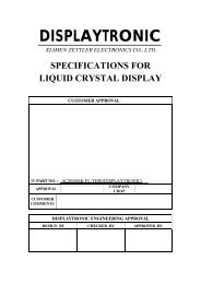
M204SD01AA MECHANICAL DRAWING<br />
FIGURE-1<br />
AN-E-2211D [10/13]
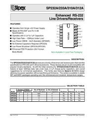
M204SD01AA CIRCUIT BLOCK DIAGRAM<br />
FIGURE-2<br />
D0∼D7<br />
WR<br />
SEL<br />
RXD<br />
TEST<br />
BUSY<br />
Vcc(+5V)<br />
GND<br />
X1<br />
OSC<br />
OSC<br />
ACK<br />
AIN<br />
CPU<br />
D0∼D7<br />
WR<br />
SEL<br />
DATA<br />
RXD<br />
RESET<br />
BLANK<br />
ADDRESS<br />
GCK<br />
GIN<br />
TEST<br />
BUSY<br />
DC/DC<br />
CONVERTER<br />
J1<br />
J2<br />
J3<br />
ANODE DRIVER<br />
(40bits)<br />
ANODE DRIVER<br />
(40bits)<br />
RAM<br />
20 digits, 4rows<br />
5×7 dot<br />
PROM<br />
GRID 1-40<br />
GRID DRIVER<br />
(40bits)<br />
PARALLEL - SERIAL SELECT<br />
CLOCK BAUDRATE SELECT<br />
ANODE DRIVER<br />
GRID DRIVER<br />
FILAMENT<br />
ANODE 1-70<br />
AN-E-2211D [11/13]
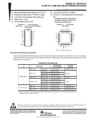
M204SD01AA DISPLAY CHARACTER CODE<br />
FIGURE-3<br />
D7<br />
D6<br />
D5<br />
D4<br />
0<br />
0<br />
0<br />
0<br />
0<br />
0<br />
0<br />
1<br />
0<br />
0<br />
1<br />
0<br />
0<br />
0<br />
1<br />
1<br />
0<br />
1<br />
0<br />
0<br />
0<br />
1<br />
0<br />
1<br />
0<br />
1<br />
1<br />
0<br />
D3 D2 D1 D0 0 1 2 3 4 5 6 7 8 9 A B C D E F<br />
0<br />
1<br />
1<br />
1<br />
1<br />
0<br />
0<br />
0<br />
1<br />
0<br />
0<br />
1<br />
1<br />
0<br />
1<br />
0<br />
1<br />
0<br />
1<br />
1<br />
1<br />
1<br />
0<br />
0<br />
1<br />
1<br />
0<br />
1<br />
1<br />
1<br />
1<br />
0<br />
1<br />
1<br />
1<br />
1<br />
0 0 0 0<br />
0<br />
DP<br />
SP<br />
0 0 0 1<br />
1<br />
DC1<br />
0 0 1 0<br />
2<br />
DC2<br />
0 0 1 1<br />
3<br />
DEF<br />
0 1 0 0<br />
4<br />
DIM<br />
0 1 0 1<br />
5<br />
0 1 1 0<br />
6<br />
0 1 1 1<br />
7<br />
1 0 0 0<br />
8<br />
BS<br />
1 0 0 1<br />
9<br />
HT<br />
1 0 1 0<br />
A<br />
LF<br />
1 0 1 1<br />
B<br />
1 1 0 0<br />
C<br />
1 1 0 1<br />
D<br />
CR<br />
UF0<br />
1 1 1 0<br />
E<br />
UF1<br />
1 1 1 1<br />
F<br />
RST<br />
UF2<br />
SP:SPACE<br />
AN-E-2211D [12/13]
5. WARRANTY<br />
This display module is guaranteed for 1 year after shipment from FUTABA.<br />
6. OPERATING RECOMMENDATION<br />
6-1. Avoid applying excessive shock or vibration beyond the specification for this module.<br />
6-2. Since VFDs are made of glass material, careful handling is important.<br />
6-3. Applying lower voltage than the specified may cause non activation for selected pixels.<br />
Conversely, higher voltage may cause non-selected pixel to be activated. If such a<br />
phenomenon is observed, check the voltage level of the power supply.<br />
6-4. Avoid plugging or unplugging the interface connection with the power on.<br />
6-5. If the start up time of the supply voltage is slow, the controller may not be reset.<br />
The supply voltage must be risen up to the specified voltage level within 30msec.<br />
6-6. Avoid using the module where excessive noise interference is expected. Noise affects the<br />
interface signal and causes improper operation.<br />
Keep the length of the interface cable less than 50cm (When the longer cable is required,<br />
please contact FUTABA engineering.).<br />
6-7. When power supply is turned off, the capacitor does not discharge immediately.<br />
The high voltage applied to the VFD must not contact the controller IC. (The shorting of the<br />
mounted components within 30 seconds after power off may cause damage.)<br />
AN-E-2211D [13/13]