rxdl2 per rxq2.pdf - Telecontrolli
rxdl2 per rxq2.pdf - Telecontrolli rxdl2 per rxq2.pdf - Telecontrolli
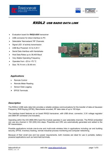
RXDL2 USB RADIO DATA LINK • Evaluation board for RXQ2-XXX transceiver • USB connector for direct interface to PC • Selectable ‘Narrowband’ RF Channels • Signal LED of activity transmission • USB Bus Powered: 4.0 to 5.25 V • Serial Data Interface with Handshake • Host Data Rates up to 38,400 Baud • Very Stable Operating Frequency • Operates from –20 to +70 °C • Size: 78.74 mm x 30.48 mm Applications • Remote Control • Remote Meter Reading • Sensor Data Logging • EPOS Terminals Description The RXDL2 (USB radio data link) provides a reliable wireless communications for the transfer of data at Gaussian Frequency Shift Keying (GFSK), Manchester encoded, RF data rates of up to 100 kbps. The interface board features an on board RXQ2 transceiver, with USB driver, connector, 3.3V voltage regulator and SMA RF connector (not included). Operating within the 433 (868) MHz band the module operates in user selectable channels. The RXQ2 embedded can use any channel in 100 (200) kHz steps. Preamble and CRC are automatically generated and added to the RF transmission. Possible applications include one-to-one and multi-node wireless links in applications including car and building security, EPOS, inventory tracking, remote industrial process monitoring and computer networking. Because of their small size and low power requirements, both modules are ideal for use in portable, batterypowered applications such as hand-held terminals. telecontrolli srl web site: www.telecontrolli.com page 1 of 6 RXDL2 : rev. 1.0
- Page 2 and 3: Mechanical Details DIP Switch Confi
- Page 4 and 5: Operation The Host Data Rate switch
- Page 6: Antenna Design The design and posit
RXDL2 USB RADIO DATA LINK<br />
• Evaluation board for RXQ2-XXX transceiver<br />
• USB connector for direct interface to PC<br />
• Selectable ‘Narrowband’ RF Channels<br />
• Signal LED of activity transmission<br />
• USB Bus Powered: 4.0 to 5.25 V<br />
• Serial Data Interface with Handshake<br />
• Host Data Rates up to 38,400 Baud<br />
• Very Stable O<strong>per</strong>ating Frequency<br />
• O<strong>per</strong>ates from –20 to +70 °C<br />
• Size: 78.74 mm x 30.48 mm<br />
Applications<br />
• Remote Control<br />
• Remote Meter Reading<br />
• Sensor Data Logging<br />
• EPOS Terminals<br />
Description<br />
The RXDL2 (USB radio data link) provides a reliable wireless communications for the transfer of data at Gaussian<br />
Frequency Shift Keying (GFSK), Manchester encoded, RF data rates of up to 100 kbps.<br />
The interface board features an on board RXQ2 transceiver, with USB driver, connector, 3.3V voltage regulator<br />
and SMA RF connector (not included).<br />
O<strong>per</strong>ating within the 433 (868) MHz band the module o<strong>per</strong>ates in user selectable channels. The RXQ2 embedded<br />
can use any channel in 100 (200) kHz steps. Preamble and CRC are automatically generated and added to the<br />
RF transmission.<br />
Possible applications include one-to-one and multi-node wireless links in applications including car and building<br />
security, EPOS, inventory tracking, remote industrial process monitoring and computer networking.<br />
Because of their small size and low power requirements, both modules are ideal for use in portable, batterypowered<br />
applications such as hand-held terminals.<br />
telecontrolli srl web site: www.telecontrolli.com page 1 of 6<br />
RXDL2 : rev. 1.0
Mechanical Details<br />
DIP Switch Configurations<br />
DIP<br />
Switch<br />
Name Type Description<br />
1 PD (Power Down) In OFF : Power Down mode; ON : O<strong>per</strong>ating mode.<br />
2,3 Data Rate In Host Data Rate selection (see next table).<br />
4 Configuration In OFF : Configuration mode; ON : O<strong>per</strong>ating mode.<br />
5 RTS In OFF, OFF : RTS,CTS Disabled<br />
6 CTS Out ON, ON : RTS,CTS Enabled<br />
Host Data Rate Selection<br />
DR1 (SW2) DR2 (SW3) Baud Rate<br />
OFF OFF 4,800<br />
ON OFF 9,600<br />
OFF ON 19,200<br />
ON ON 38,400<br />
telecontrolli srl web site: www.telecontrolli.com page 2 of 6<br />
RXDL2 : rev. 1.0
Technical Specifications<br />
• Absolute Maximum Rating<br />
O<strong>per</strong>ating tem<strong>per</strong>ature: -20 °C to +80 °C<br />
Storage tem<strong>per</strong>ature: -40 °C to +100 °C<br />
USB Supply Voltage: 5.5V<br />
• Electrical Characteristics<br />
Min. Typ. Max. Units Notes<br />
DC Levels<br />
USB Supply voltage 4.0 5 5.25 V<br />
Supply current (Transmit mode @ +10 dBm) 31 mA<br />
Supply current (Receive mode) 23 mA<br />
RF<br />
Working frequency : 433 MHz band<br />
430.0<br />
440.0<br />
868 MHz band<br />
860.0<br />
880.0<br />
MHz 1<br />
Receiver sensitivity -100 dBm<br />
Transmitter RF power out +10 dBm<br />
Frequency deviation +/-50 kHz<br />
GFSK Manchester encoded data rate 100 kbps<br />
O<strong>per</strong>ating tem<strong>per</strong>ature -20 +70 °C<br />
Dynamic Timing<br />
Power up to stable receiver data out 30 msec<br />
Power up to full RF out 30 msec<br />
Standby to Receive mode 1 msec<br />
Standby to Transmit mode 1 msec<br />
Note<br />
1. The application o<strong>per</strong>ating frequency must be chosen to comply with the Short Range device regulation in the area of o<strong>per</strong>ation<br />
telecontrolli srl web site: www.telecontrolli.com page 3 of 6<br />
RXDL2 : rev. 1.0
O<strong>per</strong>ation<br />
The Host Data Rate switches (SW 2,3) are read when the PD switch goes high (SW1 = ON). The RXQ2 must be<br />
put into standby mode by taking the PD pin low (SW1 = OFF) in order to change the selection.<br />
The size of RF data packets are set during configuration. If fewer bytes are received by the RXQ2 transceiver<br />
than the preset size, then after 10ms from the last byte received from the host, the RF packet will be processed<br />
(expanded to meet the preset packet size) and transmitted. The RF data packet size must be set the same for<br />
transmitter and receiver, otherwise the received packets will be discarded.<br />
In order to optimize data rate , in a point-to-point configuration where data is mostly being sent in one direction,<br />
the packet size for one data direction can be set to the maximum size, however the reverse direction may be set<br />
to a smaller packet size, to implement an acknowledge reply for example.<br />
No RF packets will be received by the module when it is in power down mode.<br />
Each RXQ2 has its own preset address. This is set during configuration. Any data received is examined and the<br />
address header, embedded within the data packet, is compared with the RXQ2 address. Only data received with<br />
matching address will be processed and output to the host, all other data will be discarded.<br />
All RXQ2 modules are shipped with a default address of 7E7E7E7E.<br />
Block Diagram<br />
USB<br />
Connector<br />
USB to UART<br />
Converter<br />
TRANSCEIVER<br />
Driver Installation<br />
To utilize the RXDL2 you must install on your PC the Virtual COM Port Drivers for the CP210x family of devices<br />
available at Silicon Labs site:<br />
https://www.silabs.com/products/interface/usbtouart/Pages/default.aspx<br />
telecontrolli srl web site: www.telecontrolli.com page 4 of 6<br />
RXDL2 : rev. 1.0
RXDL2 and embedded RXQ2 configuration<br />
The configuration of the RXDL2 board may be changed by setting the Configuration switch low (SW4 = OFF) and<br />
sending a set of configuration data bytes.<br />
Byte Name Description Default Value (hex)<br />
0 MSB 7E<br />
1 7E<br />
Destination Address<br />
2 7E<br />
3<br />
LSB<br />
7E<br />
4 MSB 7E<br />
5 7E<br />
RXQ2 Address<br />
6 7E<br />
7<br />
8 RF Channel<br />
9 Tx Power<br />
LSB<br />
100 kHz step (433 band)<br />
200 kHz step (868 band)<br />
00 = -10 dBm<br />
01 = -2 dBm<br />
02 = +6 dBm<br />
7E<br />
6B (433,1 MHz)<br />
75 (868,2 MHz)<br />
03 = +10 dBm<br />
10 Tx data packet size 1E (30 bytes)<br />
11 Rx data packet size 1E (30 bytes)<br />
The RF Channel is calculated as:<br />
433 MHz working frequency : Configuration value (decimal) = (desired RF frequency - 422.4MHz) * 10<br />
00<br />
868 MHz working frequency : Configuration value (decimal) = [(desired RF frequency / 2) - 422.4MHz] * 10<br />
Note : calculated value must be converted into hexadecimal format.<br />
The RXDL2 is programmed through the same port that is used for sending/receiving data. An RS232 terminal<br />
emulator (such as LABVIEW) is an ideal tool.<br />
Connect the RXDL2 directly (or via serial straight through cable) to the PC USB port.<br />
To enter configure mode, put Configuration pin low (SW4 OFF) and run the LABVIEW program<br />
(RXQ2_Setting.vi: free download from our web site) : in this mode the radio link is disabled. The RS232 PC port<br />
should be set with the following settings:<br />
8 bit data, no parity, 1 start bit, 1 stop bit, no flow control.<br />
Data Rate is the same setted on the radio data link (see Host Data Rate Selection TAB).<br />
After all parameters choice (Addresses, Frequency, Port, etc.) on the LABVIEW front panel, just run the<br />
program.<br />
To return in the o<strong>per</strong>ating mode SW4 must be setted ON.<br />
For further details on Configuration Mode, see also RXQ2 Transceiver Datasheet.<br />
Labview is a trade mark of National Instruments<br />
telecontrolli srl web site: www.telecontrolli.com page 5 of 6<br />
RXDL2 : rev. 1.0
Antenna Design<br />
The design and positioning of the aerial is as crucial as the module <strong>per</strong>formance itself in achieving a good<br />
wireless system range. The following will assist the designer in maximizing system <strong>per</strong>formance.<br />
The RF ground pin should be connected to a ground plane which should shield the aerial connection and the<br />
PCB layout around the aerial track itself should be such as to give a 50 Ohm impedance. The aerial should be<br />
kept as far away from sources of electrical interference as physically possible. The specified power supply<br />
decoupling capacitors should be placed close to the module as possible and have direct connections to the<br />
relevant pins.<br />
The antenna ‘hot end’ should be kept clear of any objects, especially any metal as this can severely restrict the<br />
efficiency of the antenna to receive power. Earth planes restricting the radiation path of the antenna will also have<br />
the same effect.<br />
The best range will be achieved with either a straight piece of wire, rod or PCB track @ ¼ wavelength Increased<br />
range may be achieved if this ¼ wave antenna is placed <strong>per</strong>pendicular to and in the middle of a solid earth plane<br />
measuring at least 16cm radius. In this case, the antenna should be connected to the module using 50 Ohm<br />
coaxial cable and the PCB track layout tips given above should be observed.<br />
Helical Antenna<br />
Whip Antenna<br />
RF<br />
RF<br />
34 mm @ 433 MHz 15.5 cm @ 433 MHz<br />
17 turns equally spaced<br />
∅ = 5 mm inside<br />
Helical Antenna<br />
Whip Antenna<br />
RF<br />
RF<br />
20 mm @ 868 MHz 7 cm @ 868 MHz<br />
9.5 turns equally spaced<br />
∅ = 6 mm inside<br />
telecontrolli srl web site: www.telecontrolli.com page 6 of 6<br />
RXDL2 : rev. 1.0


