Magnetic Field Sensor
Magnetic Field Sensor
Magnetic Field Sensor

Create successful ePaper yourself
Turn your PDF publications into a flip-book with our unique Google optimized e-Paper software.
<strong>Magnetic</strong> <strong>Field</strong> <strong>Sensor</strong><br />
KMR 360(preliminary)<br />
General Description<br />
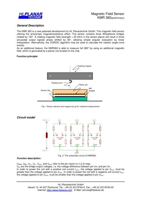
The KMR 360 is a new patented development by HL Planartechnik GmbH. This magnetic field sensor<br />
utilizing the anisotropic magnetoresistance effect. The sensor contains three Wheatstone bridges<br />
rotated by 120°. A rotating magnetic field (strength > 25 kA/m in the sensor plane) will result in three<br />
sinusoidal output signals phase shifted by 60°, allowing simple angular evaluation by linear<br />
interpolation. Alternatively, the CORDIC algorithm may be used to calculate the rotation angle more<br />
exactly.<br />
As an additional feature, the KMR360 is able to measure full 360° by using an additional magnetic<br />
field, which is generated by a planar coil located on the chip.<br />
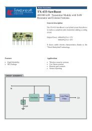
Function principle:<br />
Rotating magnet<br />
S<br />
N<br />
Rotating axis<br />
Planar coil<br />
<strong>Sensor</strong> die<br />
MR<br />
bridges<br />
Fig: 1 <strong>Sensor</strong> element and magnet set up for rotational measurement<br />
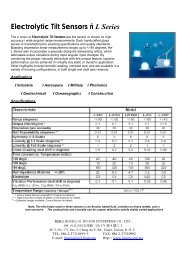
Circuit model<br />
Function description:<br />
Fig. 2: The schematic circuit of KMR360.<br />
U GND , U Bn , U n+ , U n- , U coil+ and U coil- refer to the pin name (n=1,2,3) resp..<br />
U an are the bridge output voltages, i.e. the voltage difference between pin Un + and pin Un - .<br />
In order to power the coil with a positive coil current I coil+ , the voltage applied to pin U coil+ must be<br />
greater than the voltage applied to pin U coil- . In order to power the coil with a negative coil current I coil- ,<br />
the voltage applied to pin U coil+ must be smaller than the voltage applied to pin U coil- .<br />
HL-Planartechnik GmbH<br />
Hauert 13, 44 227 Dortmund, Tel.: +49 (0) 231/9740-0, Fax.: +49 (0) 231/9740-20<br />
Internet: http://www.hlplanar.com E-Mail: service@hlplanar.de
<strong>Magnetic</strong> <strong>Field</strong> <strong>Sensor</strong><br />
KMR 360(preliminary)<br />
Characteristic Curves<br />
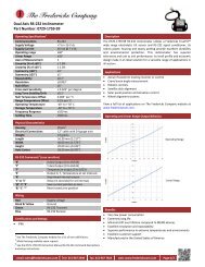
The working principle of the KMR360 is shown in figures 3 and 4: Figure 3 depicts the output signals<br />
U an+ respective U an- of the n=1,2,3 Wheastone bridges with an additional coil field created by alternate<br />
coil current I coil+ respective I coil- .<br />
10,0<br />
KMR360: Output Signals for Alternating Coil Current<br />
(H 0 =25 kA/m; Icoil=+/- 10 mA)<br />
Output Signal Ua,n(Icoil) [mV/V]<br />
8,0<br />
6,0<br />
4,0<br />
2,0<br />
0,0<br />
-2,0<br />
-4,0<br />
-6,0<br />
-8,0<br />
Ua1(+)<br />
Ua2(+)<br />
Ua3(+)<br />
Ua1(-)<br />
Ua2(-)<br />
Ua3(-)<br />
-10,0<br />
0 30 60 90 120 150 180 210 240 270 300 330 360<br />
<strong>Field</strong> Angle<br />
ω [deg]<br />
Fig. 3: Typical output signal curves without (solid) and with (dashed) coil field for KMR360<br />
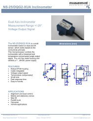
0,300<br />
KMR360: Difference Signal (H 0 =25 kA/m, Icoil=+/- 10 mA)<br />
Output Difference Signal Ua,n [mV/V]<br />
0,200<br />
0,100<br />
0,000<br />
-0,100<br />
-0,200<br />
Ua1<br />
Ua2<br />
Ua3<br />
-0,300<br />
0 30 60 90 120 150 180 210 240 270 300 330 360<br />
<strong>Field</strong> Angle<br />
ω [deg]<br />
Fig. 4: Signal change due to additional coil field<br />
Fig. 4 shows their difference signals ∆U an = U an+ -U an- .<br />
By analysing the signs the calculated angle can clearly be assigned within a range of 0° … 360°.<br />
HL-Planartechnik GmbH<br />
Hauert 13, 44 227 Dortmund, Tel.: +49 (0) 231/9740-0, Fax.: +49 (0) 231/9740-20<br />
Internet: http://www.hlplanar.com E-Mail: service@hlplanar.de
<strong>Magnetic</strong> <strong>Field</strong> <strong>Sensor</strong><br />
KMR 360(preliminary)<br />
Specification:<br />
Parameter Condition Symbol Min Typ Max Unit<br />
Mechanical Dimensions<br />
Chipsize 1.8x1.8 mm*mm<br />
Chip thickness 400 µm<br />
Padsize 120*120 µm*µm<br />
Padmaterial Aluminium d Al 1 µm<br />
Operation Limits<br />
Max. voltage depends on package Ucc,max 10 V<br />
Max. current sense current Icc,max 10 mA<br />
Operating temperature T -40 +125 °C<br />
Storage temperature Tst -40 +125 °C<br />
Temperature range for TC<br />
measurements<br />
Tm -25 +125 °C<br />
<strong>Sensor</strong> Specification<br />
Applied magnetic field H appl TBD 35 TBD kA/m<br />
Bridge resistance Rb 0.8 1 1.2 kΩ<br />
Signal amplitude H appl = 50 kA/m, T=RT ∆U/U 15 TBD TBD mV/V<br />
Angular accuracy<br />
H appl = 25 kA/m,<br />
∆α 2 °<br />
T=RT; |U off|
<strong>Magnetic</strong> <strong>Field</strong> <strong>Sensor</strong><br />
KMR 360(preliminary)<br />
Housing:<br />
Packaging is planned in SM 14 housing.<br />
Fig. 5 Sample housing SM 14<br />
Applications:<br />
- <strong>Magnetic</strong> encoder<br />
- Contact less potentiometer<br />
- Electric motor<br />
- Ventilation system / Valve system<br />
- Turn table<br />
- Automotive<br />
- Steering angle<br />
- Chassis<br />
- Camshaft<br />
- Rpm-detection<br />
- Throttle valve<br />
- Gear control<br />
HL-Planartechnik GmbH<br />
Hauert 13, 44 227 Dortmund, Tel.: +49 (0) 231/9740-0, Fax.: +49 (0) 231/9740-20<br />
Internet: http://www.hlplanar.com E-Mail: service@hlplanar.de<br />
Stand: 12.05.03<br />
Rev.1.2, Design:Zn