
Create successful ePaper yourself
Turn your PDF publications into a flip-book with our unique Google optimized e-Paper software.
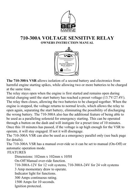
710-<strong>300A</strong> VOLTAGE SENSITIVE RELAY<br />
OWNERS INSTRUCTION MANUAL<br />
NOTE:<br />
WHEN RETURNING TO AUTO OPERATION AFTER MANUAL OPERATION<br />
THE HANDLE MUST BE SWITCHED TO OFF POSITION THEN TO AUTO<br />
FOR AUTO OPERATION HANDLE MUST ALIGN TO AUTO<br />
LED INDICATIONS: LED ON (CONSTANT) - AUTOMATIC MODE<br />
SLOW FLASH - EMERGENCY PARALLEL<br />
LED ON (CONSTANT) - MANUAL<br />
<strong>VSR</strong><br />
VOLTAGE SENSITIVE<br />
RELAY MODULE<br />
IGNITION PROTECTED<br />
<strong>300A</strong><br />
CUT IN 13.7V DC<br />
CUT OUT 12.8V DC<br />
The 710-<strong>300A</strong> <strong>VSR</strong> allows isolation of a second battery and electronics from<br />
harmful engine starting spikes, while allowing two or more batteries to be charged<br />
at the same time.<br />
The relay stays open when the engine is first started and remains open during<br />
initial charging until the start battery has reached a preset voltage (13.7V/27.4V).<br />
The relay then closes, allowing the two batteries to be charged together. When the<br />
engine is stopped, the voltage returns to normal levels, which allows the relay to<br />
open again, separating the start battery, eliminating the possibility of discharging<br />
the wrong battery. The 710-<strong>300A</strong> also has the additional feature of being able to<br />
be used as a paralleling solenoid for emergency starting. This can be operated<br />
through a button on the dash and will instigate for a preset time of 10 minutes.<br />
Once this 10 minutes has passed, if the voltage is up high enough for the <strong>VSR</strong> to<br />
operate, it will stay engaged. If not it will disengage.<br />
The 710-<strong>300A</strong> <strong>VSR</strong> can also be used as a emergency parallel only (see back page<br />
for details).<br />
The 710-<strong>300A</strong> <strong>VSR</strong> has a manual over-ride so it can be set to manual (On-Off) or<br />
automatic operation mode.<br />
FEATURES<br />
Dimensions: 102mm x 102mm x 105H<br />
On-Off Manual over-ride function.<br />
710-<strong>300A</strong>-12V for 12 volt systems, 710-<strong>300A</strong>-24V for 24 volt systems<br />
3 Amp momentary draw to operate.<br />
Indicator light for functions.<br />
300 Amps continuous rating.<br />
1500 Amps for 10 seconds.<br />
Ignition protected.
30<br />
20<br />
40<br />
14<br />
0<br />
16<br />
50<br />
8<br />
WIRING<br />
FIG 1<br />
-<br />
MANUAL OVERRIDE<br />
SWITCH<br />
NB: IF THE BATTERY SWITCH<br />
HAS BEEN MANUALLY<br />
SWITCHED ON THE MANUAL<br />
OVERRIDE SWITCH MUST BE<br />
ROTATED INTO THE "OFF"<br />
POSITION BEFORE BEING<br />
RETURNED INTO THE "AUTO"<br />
POSITION.<br />
RELAY (710-<strong>300A</strong>)<br />
REAR VIEW<br />
SEPERATE GREEN AND SHIELD TO<br />
DISABLE <strong>VSR</strong> SENSING, IE FOR<br />
EMEGENCY PARALLEL USE ONLY.<br />
GREEN<br />
SHIELD<br />
WHITE<br />
RED<br />
BLACK<br />
<strong>BEP</strong> 701/720/722 BATTERY SWITCH<br />
OPTIONAL SETUP IF EMERGENCY<br />
PARALLEL REQUIRED<br />
SWITCH CLOSED L.E.D INDICATOR.<br />
3 WAY WAGO<br />
PLUG (SUPPLIED).<br />
ON<br />
EMERGENCY<br />
PARALLEL SWITCH<br />
BOTH NEGATIVES MUST BE<br />
TAKEN TO THE NEGATIVE OF<br />
THE BATTERY THAT HAS ITS<br />
POSITIVE CONNECTED TO<br />
THE 710-<strong>300A</strong>'S "LOAD STUD"<br />
ENGINE<br />
.<br />
+<br />
-<br />
<strong>BEP</strong> 701/720/722 BATTERY SWITCH<br />
HOUSE BATT<br />
ISOLATOR<br />
VOLTAGE<br />
SENSITIVE<br />
LOAD<br />
BATTERY<br />
MOTOR BATT<br />
ISOLATOR<br />
PANEL<br />
DC VOLTS<br />
DC AMPS<br />
EMERGENCY PARALLEL<br />
PUSH FOR<br />
EMERGENCY PARALLEL<br />
NEGATIVE<br />
BUSS BAR<br />
12<br />
10<br />
10<br />
+
OPERATION<br />
AUTOMATIC<br />
For automatic mode the manual knob must be in the automatic position. In<br />
“automatic” mode the <strong>VSR</strong> is self-regulating. When the start battery reaches and<br />
maintains 13.7 volts (27.4V) for 5 seconds ie under charging conditions, the relay<br />
closes and allows the second battery to charge in parallel with the start battery.<br />
When the engine is running and the start battery falls below 12.8 volts (25.6V) for<br />
10 seconds, due to a heavy load winch/bow thruster etc or the charge source is<br />
removed (ie engine/alternator is stopped), the relay opens once again isolating the<br />
batteries.<br />
MANUAL<br />
When either manual position has been selected both automatic (<strong>VSR</strong>) and<br />
remote switching functions are disabled<br />
OFF: When the <strong>VSR</strong> is manually switched to the off position (see DIAG 1)<br />
the house and start batteries are electrically isolated from each other.<br />
ON: When the <strong>VSR</strong> is manually switched to the on position (see DIAG 1)<br />
the house and engine batteries are paralleled (will act as one large battery<br />
bank ie charge/discharge together).<br />
NOTE:<br />
IF UNIT HAS BEEN MANUALLY SWITCHED ON, SWITCH THE<br />
MANUAL KNOB INTO THE OFF POSITION BEFORE<br />
RETURNING IT TO THE “AUTO” POSITION.<br />
EMERGENCY PARALLEL (REMOTE PARALLEL)<br />
When the emergency parallel switch is pressed the contacts in the <strong>VSR</strong> will<br />
close, paralleling the house batteries to the flattened engine batteries. This<br />
will enable the engine to be started using the extra capacity from the house<br />
batteries. (it is recommended that any sensitive electronics be turned off<br />
during emergency parallel starting). The batteries will remain paralleled for<br />
10 minutes after which time the <strong>VSR</strong> will resume normal operation.<br />
LED INDICATIONS<br />
LED ON (constant): The <strong>VSR</strong> is on (automatic mode, contacts closed).<br />
LED OFF: The <strong>VSR</strong> is in manual on (contacts closed) or off (contacts<br />
open).<br />
FLASHING: The emergency parallel function has been activated by the<br />
remote switch (contacts closed, house and start batteries paralleled). The<br />
<strong>VSR</strong> will stay in this state for ten minutes then return to normal <strong>VSR</strong> mode.
EMERGENCY PARALLEL SWITCHING<br />
For the emergency parallel to work the emergency parallel button must be a<br />
momentary type. Refer to FIG 1 for wiring instructions<br />
EMERGENCY PARALLEL OPERATION ONLY<br />
To use the <strong>VSR</strong> as an emergency parallel switch only, separate the<br />
green and shielded wires (see DIAG 2). Ensure that any exposed wires are<br />
sealed and insulated afterwards.<br />
GREEN<br />
SHIELD GREEN SHIELD<br />
AS SUPPLIED,<br />
<strong>VSR</strong> ENABLED<br />
DIAG 2<br />
AFTER MODIFICATION,<br />
EMERGENCY PARALLEL<br />
ONLY<br />
<strong>BEP</strong> MARINE<br />
13 Tarndale Grove<br />
Albany, Auckland N.Z.<br />
Ph: +64 9 415 7261<br />
Fax: +64 9 415 9327<br />
www.bepmarine.com<br />
Email: enquiries@bepmarine.com