Rutland Furlmatic 910-3 Windcharger Owners Manual
Rutland Furlmatic 910-3 Windcharger Owners Manual
Rutland Furlmatic 910-3 Windcharger Owners Manual

Create successful ePaper yourself
Turn your PDF publications into a flip-book with our unique Google optimized e-Paper software.
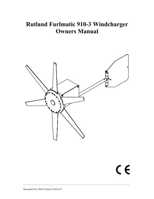
<strong>Rutland</strong> <strong>Furlmatic</strong> <strong>910</strong>-3 <strong>Windcharger</strong><br />
<strong>Owners</strong> <strong>Manual</strong><br />
_________________________________________________________________________________________<br />
_<br />
Document No: SM124 Issue D 30.01.07
Marlec Eng Co Ltd<br />
Installation Instructions<br />
INTRODUCTION……………………………………………………. 2<br />
GENERAL GUIDELINES & WARNINGS………………………….. 2<br />
CHECK YOU HAVE RECEIVED…………………………………… 4<br />
WHAT YOU WILL NEED…………………………………………… 4<br />
SITING THE WINDCHARGER…………………………………….. 5<br />
PRINCIPLE OF OPERATION………………………………………. 6<br />
TOWER CONSTRUCTION…………………………………………. 7<br />
ASSEMBLY & INSTALLATION…………………………………… 8<br />
Blade Assembly…………………………………. 8<br />
<strong>Furlmatic</strong> Tail Assembly………………………… 9<br />
Tower Preparation……………………………….. 10<br />
BATTERIES…………………………………………………………. 11<br />
CABLE SPECIFICATION…………………………………………… 12<br />
ELECTRICAL CONNECTIONS & FITTING TO TOWER………… 12<br />
Final Mechanical Check…………………………. 13<br />
BASIC WIRING DIAGRAMS………………………………………. 14<br />
UP & RUNNING…………………………………………………. 15<br />
SPECIFICATION & PERFORMANCE……………………………… 15<br />
INSPECTION & MAINTENANCE…………………………….. 16<br />
TROUBLESHOOTING…………………………………………….. 17<br />
Page<br />
_________________________________________________________________________________________<br />
_<br />
Document No: SM124 Issue D 30.01.07 1
Marlec Eng Co Ltd<br />
INTRODUCTION<br />
Installation Instructions<br />
This manual contains important information concerning your <strong>Rutland</strong> <strong>910</strong>-3<br />
<strong>Windcharger</strong> and its installation and operation.<br />
It is strongly recommended that you read this manual and familiarise yourself<br />
with its contents before installing and operating the <strong>Windcharger</strong> system.<br />
The <strong>Rutland</strong> <strong>910</strong>-3 <strong>Windcharger</strong> is designed to provide a direct current (DC)<br />
power supply via a battery bank for 12/24V equipment, lighting, etc. It is<br />
robustly constructed and designed to give many years of trouble free service<br />
with the minimum of maintenance. Please take notice of our General Guidelines<br />
for the user and Inspection and Maintenance sections.<br />
GENERAL GUIDELINES & WARNINGS!<br />
• Observe the mounting pole diameters recommended in this manual. It is<br />
essential to the effective operation of the furling tail system that the mounting<br />
pole is vertical. An unsupported tower will experience lateral movement<br />
particularly in high winds and furling will be adversely affected will potential<br />
damage to the wind turbine.<br />
• When turning, the <strong>Windcharger</strong> is capable of generating voltages in excess of<br />
the nominal voltage. The turbine must never be allowed to rotate unless it is<br />
electrically connected to a regulator or batteries. Avoid applying a short<br />
circuit to the <strong>Windcharger</strong> particularly in high winds. If a short circuit is<br />
necessary first slow the turbine as described below. Caution must be<br />
exercised at all times to avoid electric shock.<br />
• Stopping the turbine – this may be necessary to undertake battery<br />
maintenance. If possible stopping the turbine should be done in low<br />
windspeed conditions. The turbine can be slowed by rotating or orienting the<br />
tail fin upwind, this will slow the turbine sufficiently for it to be safely secured<br />
to the pole with rope. Avoid leaving the turbine tied up for any period of time,<br />
we recommend that the turbine either be covered to give protection from the<br />
weather or removed and stored in a dry location. The optional HRDX<br />
Controller incorporates a shutdown switch.<br />
• No attempt to repair the system should be made until the <strong>Windcharger</strong> is<br />
restrained from turning.<br />
_________________________________________________________________________________________<br />
_<br />
Document No: SM124 Issue D 30.01.07 2
Marlec Eng Co Ltd<br />
Installation Instructions<br />
• The <strong>Windcharger</strong> is fitted with ceramic magnets, which can be damaged by<br />
heavy handling. The main generator assembly should be treated with care<br />
during transit and assembly.<br />
• It is essential to observe the correct polarity when connecting the<br />
<strong>Windcharger</strong> and all other components into an electrical circuit. Reverse<br />
connection will damage the <strong>Windcharger</strong> and incorrect installation will<br />
invalidate the warranty.<br />
• The fuse supplied must be fitted to protect the system unless used in<br />
conjunction with a controller that is already fitted with a charge fuse.<br />
• High winds – in high winds the <strong>Windcharger</strong>’s built-in thermostat may<br />
operate to prevent the generator overheating. In this mode the output will<br />
cease and the turbine will temporarily slow down until such time as the lower<br />
level temperature is reached and the generator is once again connected and<br />
charging. This may be seen to cycle in prolonged high winds particularly in<br />
high ambient temperatures. Further the furling tail mechanism of the<br />
<strong>Furlmatic</strong> model will operate in high winds orienting the turbine out of the<br />
prevailing wind direction to slow the turbine down. It will return to face the<br />
wind as windspeeds fall and will be seen to cycle during high wind speeds.<br />
• If in doubt, refer to your dealer, a competent electrical engineer or the<br />
manufacturer.<br />
_________________________________________________________________________________________<br />
_<br />
Document No: SM124 Issue D 30.01.07 3
Marlec Eng Co Ltd<br />
CHECK YOU HAVE RECEIVED<br />
Installation Instructions<br />
• 1 x main generator assembly<br />
• 1 x tail assembly<br />
• 24 x No. 10x25mm special self-tapping screws<br />
• 6 x aerofoil blades<br />
• 1 x fuse and fuse holder<br />
• 1 x 2-way terminal block<br />
• 2 x M10 buttoncap screws<br />
• 2 x M10 shakeproof washers<br />
• 1 x 6mm Allen key<br />
In the event of loss or damage, consult your dealer or the manufacturer.<br />
WHAT YOU WILL NEED<br />
Tools<br />
• Suitable wire stripper<br />
• Small terminal screwdriver<br />
• Large flat blade screwdriver<br />
• Crosshead screwdriver<br />
• 10mm Spanner<br />
Other Items You Will Need<br />
• Tower/Mounting pole<br />
• Batteries<br />
• Battery terminals<br />
• Cable<br />
• Connector blocks (as determined by your total system)<br />
Other Items You May Have Selected from Marlec<br />
• HRS913 Regulator or HRDX Controller<br />
• Land Tower and Rigging Kit (Part Nos. CA-12/08 & CA-12/07)<br />
• Voltmeter & Ammeter<br />
SITING THE WINDCHARGER<br />
_________________________________________________________________________________________<br />
_<br />
Document No: SM124 Issue D 30.01.07 4
Marlec Eng Co Ltd<br />
Installation Instructions<br />
General Considerations<br />
The location and height of the mounting pole or tower for your wind turbine will<br />
be the major factor in the overall performance of your system. The smooth flow<br />
of wind over land and water is often interrupted by a multitude of obstructions<br />
causing wind sheer and turbulence.<br />
Wind sheer describes the interference between the fast moving upper air and the<br />
slow moving air close to the ground and the resulting decrease in average wind<br />
speed as one gets closer to the ground.<br />
Turbulence is caused by the wind passing over obstructions such as trees and<br />
buildings.<br />
Both wind sheer and turbulence diminish with height and can be overcome<br />
simply by putting the machine sufficiently high above them as shown in Fig 1.<br />
Wind speed decreases and turbulence increases where obstructions exist.<br />
Consider also that downwind obstructions can be as detrimental to performance<br />
as upwind obstructions.<br />
WIND DIRECTION<br />
AREA OF TURBULENCE<br />
Fig.1<br />
2H<br />
H<br />
2H<br />
20H<br />
_________________________________________________________________________________________<br />
_<br />
Document No: SM124 Issue D 30.01.07 5
Marlec Eng Co Ltd<br />
PRINCIPLE OF OPERATION<br />
Installation Instructions<br />
Generator<br />
The 3 phase ac generator is driven directly by the aerofoil blades, rotating<br />
permanent magnets around the fixed stator winding. The variable<br />
frequency alternating current is rectified within the generator housing, and<br />
the resulting rectified current is transmitted via the sliprings and brushes at<br />
the yaw axis to the output cable.<br />
Winding Over-Temperature Protection<br />
The generator stator winding incorporates embedded thermal protection to<br />
protect the winding from damage due to over temperature during extreme<br />
winds. On reaching the thermal protection limit, the device will reduce<br />
generator output current to allow the winding to cool, whereupon normal<br />
performance will be resumed. If the thermal protection is active, the<br />
turbine may reduce to a slow rotational speed with a corresponding<br />
reduction in charge current, this is normal.<br />
Furling Tail System<br />
The tail assembly is designed to direct the turbine into the main direction of<br />
the wind at windspeeds up to approx 15m/s. Above this the automatic<br />
“furling” mechanism is activated to turn the generator at an angle to the<br />
wind to protect the turbine, generator and supporting structure from severe<br />
electrical and mechanical loads due to high winds. When the wind speed<br />
subsides, the tail assembly will automatically return the turbine to normal<br />
operation. In prolonged gusty & turbulent conditions, the system may be<br />
seen to repeat this cycle many times. Power will be reduced during furling.<br />
For effective operation of the furling system the wind turbine must be sited<br />
to ensure it is as free as possible from turbulence and in a stable upright<br />
position.<br />
__________________________________________________________________________________________<br />
Document No: SM124 Issue D 30.01.07 6
Marlec Eng Co Ltd<br />
TOWER CONSTRUCTION<br />
Installation Instructions<br />
The <strong>Furlmatic</strong> <strong>910</strong>-3 is designed to fit inside an aluminium, stainless or<br />
steel tube with an internal diameter of 41mm with a minimum wall<br />
thickness of 5mm.<br />
A suitable mounting pole can be erected using a 6.5 metre (21 feet)<br />
galvanised (medium) tube. The tube must be supported by a minimum of<br />
four guy lines.<br />
The attachment points for the guy lines to the tower should be securely<br />
fixed to the tower.<br />
• The guy wires should be a minimum of 4mm in diameter.<br />
• The shackles should be a minimum of 5mm in diameter.<br />
• Rigging screws should be a minimum of 5mm in diameter.<br />
• All items should be galvanised or stainless steel for protection against<br />
corrosion.<br />
• Where guy lines are looped, the loop must incorporate a thimble and be<br />
fitted with a minimum of three rope grips.<br />
• All ground fixings must be made suitable according to the terrain.<br />
Fig.2<br />
Fig.3<br />
Base pivoted with gin pole<br />
Centre pivoted pole<br />
Pivot type towers are recommended as these allow for easier installation<br />
and lowering for access to the wind generator. Two forms of pivot tower<br />
are suggested in Figs 2 & 3. Non-guyed pivoting towers are available, for<br />
further details contact the dealer or manufacturer.<br />
Note: See the warnings section regarding the tower. It is essential that the<br />
tower is maintained vertically to minimise lateral movement which<br />
interferes with the effective operation of the furling tail.<br />
__________________________________________________________________________________________<br />
Document No: SM124 Issue D 30.01.07 7
Marlec Eng Co Ltd<br />
Installation Instructions<br />
ASSEMBLY AND INSTALLATION OF THE WINDCHARGER<br />
Blade Assembly (Fig. 4)<br />
1. Place the generator assembly on a flat surface hub-side down.<br />
2. Position blade as shown. The blades will only fit one way round.<br />
Insert the protrusion at the trailing edge of the blade root fixing first into<br />
socket to align with the corresponding recess in the blade socket. The<br />
blade can then be easily inserted with a lever action. Gentle assistance with<br />
a soft faced mallet may be required.<br />
3. Four screws are required for each blade. First secure each blade with<br />
two of the special self-tapping screws provided.<br />
4. Fit the remaining 2 blade screws from the front of the generator hub.<br />
5. Check tightness of all screws. (Do not over-tighten).<br />
Fig.4<br />
NB. IT IS IMPORTANT THAT 4 SCREWS PER BLADE ARE<br />
FITTED.<br />
__________________________________________________________________________________________<br />
Document No: SM124 Issue D 30.01.07 8
Marlec Eng Co Ltd<br />
<strong>Furlmatic</strong> Tail Assembly (Fig. 5)<br />
Installation Instructions<br />
1. Remove the cover from the main housing.<br />
2. Remove the M6 nut, washers and bolt from the tail boom.<br />
3. Insert the tail boom into the saddle on the underside front of the housing.<br />
Ensure the tail assembly is the correct way up. (refer to pictures in this<br />
manual & the text on the tail label).<br />
4. Re-fit bolt washers & nut removed in 2, passing the bolt through the tail<br />
boom and windshaft housing. Tighten all fasteners.<br />
5. Replace cover.<br />
Note: Do not remove the silicone protectors from the tail stops!<br />
Tail Boom<br />
Fasteners<br />
Fig. 5<br />
NB. The tail fin is set at an angle of 15°<br />
from vertical. Check that the tail fin is<br />
positioned as shown in the diagram (as<br />
viewed from rear of the <strong>Windcharger</strong>)<br />
__________________________________________________________________________________________<br />
Document No: SM124 Issue D 30.01.07 9
Marlec Eng Co Ltd<br />
Tower Preparation (Fig. 6)<br />
Installation Instructions<br />
Having selected a suitable pole from the guidelines on page 7:<br />
1. The post adaptor fitted to the FM<strong>910</strong>-3 is designed to fit inside a<br />
standard 41mm (1⅝") internal diameter tube. The adaptor is provided<br />
with a flat on one side to clear the weld seam on seamed pipe.<br />
2. Mark and centre-punch two positions diametrically opposite, at 90° to<br />
the pipe seam if necessary, 20mm (NOTE: Use metric measurements for<br />
this operation) from the top of the tube.<br />
3. Drill two holes 10.5mm (NOTE: Use metric measurements for this<br />
operation) in diameter on centre-punch positions.<br />
Note: When using the <strong>Rutland</strong> Land Tower Kit, items 2 and 3 can be ignored as<br />
the unit is pre-drilled.<br />
Fig.<br />
BATTERIES<br />
__________________________________________________________________________________________<br />
Document No: SM124 Issue D 30.01.07 10
Marlec Eng Co Ltd<br />
Installation Instructions<br />
Leisure/Deep Cycle batteries are specifically designed for good<br />
performance in terms of charge/discharge cycles. Batteries are the most<br />
important part of your battery charging system and should be sized<br />
according to your load requirements and provide at least 3 days reserve<br />
capacity. This will reduce cycling, prolong the life of the battery and<br />
ensure system reliability during periods of low wind<br />
Permanent connections should always be made to the battery terminals.<br />
Never use crocodile clips or similar devices. Battery terminals should be<br />
well greased with petroleum jelly or similar.<br />
We strongly recommend that one of the voltage regulators available from<br />
Marlec is fitted to prevent batteries becoming overcharged in strong winds<br />
and is essential with gel/sealed batteries.<br />
Batteries may be linked as follows:<br />
• In parallel to increase amp hours (Fig.6).<br />
• In series to increase voltage (Fig.7).<br />
Red is + Positive<br />
Black is - Negative<br />
Total = 12v<br />
120Ah<br />
1440Wh<br />
Fig.6<br />
Total = 24v<br />
60Ah<br />
1440Wh<br />
Fig.7<br />
12v<br />
60Ah<br />
12v<br />
60Ah<br />
12v<br />
60Ah<br />
12v<br />
60Ah<br />
CABLE SPECIFICATION<br />
__________________________________________________________________________________________<br />
Document No: SM124 Issue D 30.01.07 11
Marlec Eng Co Ltd<br />
Installation Instructions<br />
The cable used for connection of the <strong>Windcharger</strong> to the batteries should be<br />
in accordance with table 1. The use of a smaller cable than recommended<br />
will reduce the performance of the charging system.<br />
Cable and connectors are available from your dealer or the manufacturer.<br />
Cable Run<br />
(m)<br />
Cable Size<br />
(mm²)<br />
12 Volt<br />
Cable Size<br />
(mm²)<br />
24 Volt<br />
0-20 2.5 1.5<br />
21-30 4 2.5<br />
31-45 6 4<br />
46-80 10 6<br />
Table.1<br />
ELECTRICAL CONNECTION & FITTING TO THE TOWER<br />
1. Run the cable selected (see Table 1) down the inside of the pole.<br />
2. Select one of the 2 basic systems on page 14 and follow the manual<br />
provided with the charge regulator selected.<br />
3. Fit the in-line fuse and fuse holder in the circuit where the HRS type or<br />
no regulator is used. It is essential that a charge fuse is fitted but note<br />
that some Marlec controllers incorporate one negating the need for a<br />
separate fuse. Cut the fuse holder cable and strip back the ends to allow<br />
connection in the circuit.<br />
Fig. 8<br />
20A Fuse<br />
and Fuse holder<br />
4. Connect the Wincharger flying lead to the cable protruding from the top<br />
of the tower using the connector block supplied, taking care to observe<br />
__________________________________________________________________________________________<br />
Document No: SM124 Issue D 30.01.07 12
Marlec Eng Co Ltd<br />
Installation Instructions<br />
polarity. Connect the <strong>Windcharger</strong> + to cable + and <strong>Windcharger</strong> – to<br />
cable –<br />
Red is +Positive<br />
Black is –Negative<br />
5. Wrap the connection with insulation tape to secure/protect from the<br />
environment. Alternatively join the cables using a latching type plug and<br />
socket.<br />
6. Locate the <strong>Windcharger</strong> into the tower whilst gently easing the cable<br />
from the tower base to ensure the cable is not trapped. Secure the<br />
<strong>Windcharger</strong> to the tower using the button cap screws and shake-proof<br />
washers provided. Tighten using the 6mm Allen key supplied.<br />
FINAL MECHANICAL CHECK<br />
1. Check the tightness of the blade fixing screws and generator mounting<br />
screws.<br />
2. Check free rotation of the hub and yaw axis.<br />
__________________________________________________________________________________________<br />
Document No: SM124 Issue D 30.01.07 13
Marlec Eng Co Ltd<br />
Installation Instructions<br />
Regulator and Fuse<br />
Wiring Diagram<br />
REGULATOR<br />
FM<strong>910</strong>-3 WIND<br />
GENERATOR<br />
RED<br />
BROWN<br />
BLACK<br />
BLACK<br />
RED<br />
CHARGE FUSE<br />
BATTERY<br />
Charge Controller<br />
Wiring Diagram<br />
FM<strong>910</strong>-3 WIND<br />
GENERATOR<br />
RED<br />
BLACK<br />
BATTERY<br />
BATTERY<br />
__________________________________________________________________________________________<br />
Document No: SM124 Issue D 30.01.07 14
Marlec Eng Co Ltd<br />
UP AND RUNNING<br />
Installation Instructions<br />
• Before raising and securing the wind generator, check that:<br />
1. All final mechanical checks have been made.<br />
2. The cable is not trapped.<br />
3. All electrical connections are secure and safe.<br />
• The wind generator can now be raised into position.<br />
Take care to avoid all moving parts when raising and lowering the wind<br />
generator.<br />
• When raised, secure the structure firmly in an upright position. The<br />
performance of your <strong>Windcharger</strong> can be impaired if the pole is not vertical.<br />
SPECIFICATION AND PERFORMANCE<br />
14<br />
7<br />
CHARGE CURRENT INTO 12v BATTERY (AMPS)<br />
12<br />
10<br />
8<br />
6<br />
4<br />
2<br />
WINDSPEED CONVERSION<br />
MPH = M/S x 2.23<br />
Knots = M/S x 1.94<br />
6<br />
5<br />
4<br />
3<br />
2<br />
1<br />
CHARGE CURRENT INTO 24v BATTERY (AMPS)<br />
0<br />
0<br />
0 5 10 15 20 25 30 35 40<br />
WINDSPEED M/S<br />
__________________________________________________________________________________________<br />
Document No: SM124 Issue D 30.01.07 15
Marlec Eng Co Ltd<br />
INSPECTION AND MAINTENANCE<br />
Installation Instructions<br />
The <strong>Rutland</strong> <strong>Furlmatic</strong> <strong>910</strong>-3 requires no scheduled maintenance but an annual<br />
inspection should be carried out to monitor the general condition of the system.<br />
• Before inspection, the turbine should either be lowered to the ground or tied to<br />
prevent the generator from turning. To stop the generator from turning follow<br />
one of the procedures below:<br />
1) Lower the windcharger on its tower to the ground, coming to rest on a structure<br />
that will prevent the windcharger from striking the ground. Take care that all<br />
persons are clear of the area. The turbine will eventually slow down. Tie a blade<br />
to the mounting pole to prevent it from rotating.<br />
2) If the tail boom is safely accessible, using the tail boom, rotate the generator out<br />
of the wind; the turbine will eventually slow down. Tie a blade to the mounting<br />
pole to prevent it from rotating.<br />
• Whilst the generator is stationary, the following routine checks should be<br />
performed:<br />
1) Check the blade screws for tightness.<br />
2) Check all other nuts, bolts and screws for tightness.<br />
3) Check the yaw axis for free rotation.<br />
4) Check the tail fin moves freely.<br />
5) Check tower assembly for condition.<br />
6) Check the tension of the guy wires if applicable. The tension of guy wires<br />
should be checked frequently during the first year.<br />
7) The unit can be wiped with a mild detergent and rinsed with water to remove<br />
dirt and debris.<br />
__________________________________________________________________________________________<br />
Document No: SM124 Issue D 30.01.07 16
Marlec Eng Co Ltd<br />
TROUBLESHOOTING<br />
Installation Instructions<br />
In the unlikely event that your <strong>Rutland</strong> <strong>Furlmatic</strong> <strong>910</strong>-3 should develop a defect,<br />
the turbine should first be tied to prevent the blades from turning to perform the<br />
static tests below. (Follow the procedure described in the Inspection and<br />
Maintenance section) It will be necessary to let it run for the tests to check for<br />
power production.<br />
1. Read the Electrical Connection (page 12) and Up & Running (page 15)<br />
sections and be satisfied that your system complies.<br />
2. Is there sufficient wind? The <strong>Rutland</strong> <strong>910</strong>-3 needs approximately 5 knots wind<br />
speed to start charging. The wind speed across the turbine blades may be greatly<br />
reduced in built-up area compared with weather reports for example.<br />
3. Static Tests:<br />
• Is the battery in good condition? Check the voltage and electrolyte level of<br />
each battery.<br />
• Check electrical continuity throughout the system, especially corrosion and<br />
poor connections in cable joins and connector blocks.<br />
4. Running Tests:<br />
• Check for power output from the <strong>Windcharger</strong>, following this procedure:<br />
A. Set a digital multimeter to DC Amps, scale of between 5 and 10 if possible.<br />
Connect the meter positive (+) probe to the wind generator output positive cable<br />
and the meter negative (-) to the regulator input positive. Provided there is<br />
sufficient wind there should be a current reading. This establishes that power is<br />
being delivered.<br />
B. Using the same multimeter setting as above measure between the regulator to<br />
battery + and the battery +. Provided there is sufficient wind there should be a<br />
current reading. This establishes if power is passing through the regulator.<br />
C. If both above are unsuccessful set the multimeter to DC Volts. Disconnect the<br />
wind generator from the regulator and connect the meter + to the wind gen +<br />
and the meter – to the wind gen -. Provided there is sufficient wind there should<br />
be a variable voltage reading according to the speed of the wind seen at the<br />
wind turbine. This will establish if the wind generator is able to deliver power<br />
or not.<br />
D. If tests A and C are successful but test B fails to produce results connect the<br />
wind gen directly to the battery. Set the digital multimeter to DC Amps and<br />
measure power between the wind gen + and the battery +. If a reading is<br />
measured, providing there is sufficient wind, then the regulator is faulty.<br />
E. If the wind turbine fails to deliver any current or open circuit V reading<br />
undertake the further tests below.<br />
5. Mechanical inspection. It may be necessary to remove the <strong>Windcharger</strong> from<br />
__________________________________________________________________________________________<br />
Document No: SM124 Issue D 30.01.07 17
Marlec Eng Co Ltd<br />
its pole for the following tests.<br />
Installation Instructions<br />
• Check the brushes and slipring for wear or damage. To inspect the brushes,<br />
remove the cover from the main housing by removing the four fixing screws.<br />
The brushes and slipring can be then be inspected by removing the four selftapping<br />
screws holding the brush holder assembly in place. Remove any black<br />
deposits from slipring with emery paper. Heavy deposits and reduced power<br />
indicate a possible reverse connection to the battery (see Page 11).<br />
• Check hub for free rotation with generator disconnected from battery.<br />
If the hub does not rotate freely, check for a possible short circuit in the wiring.<br />
If no wiring fault is found refer to your dealer or manufacturer.<br />
If the above checks have identified a need for spare parts or failed to identify<br />
the problem you should contact Marlec who can advise you of your nearest<br />
distributor in their world wide network. In the first instance we recommend<br />
that you contact the company from whom the product was originally<br />
purchased.<br />
If in doubt, refer to your dealer or manufacturer.<br />
__________________________________________________________________________________________<br />
Document No: SM124 Issue D 30.01.07 18
Marlec Eng Co Ltd<br />
Installation Instructions<br />
Notes<br />
__________________________________________________________________________________________<br />
Document No: SM124 Issue D 30.01.07 19
Marlec Eng Co Ltd<br />
Installation Instructions<br />
Notes<br />
__________________________________________________________________________________________<br />
Document No: SM124 Issue D 30.01.07 20
Marlec Eng Co Ltd<br />
Installation Instructions<br />
LI M I T E D W A R R A N T Y<br />
The Marlec Engineering Company Limited Warranty provides free replacement cover for<br />
all defects in parts and workmanship for 12 months from the date of purchase. Marlec's<br />
obligation in this respect is limited to replacing parts which have been promptly reported<br />
to the seller and are in the seller’s opinion defective and are so found by Marlec upon<br />
inspection. A valid proof of purchase will be required if making a warranty claim.<br />
Defective parts must be returned by prepaid post to the manufacturer Marlec Engineering<br />
Company Limited, <strong>Rutland</strong> House, Trevithick Road, Corby, Northamptonshire, NN17<br />
5XY, England, or to an authorised Marlec agent.<br />
This Warranty is void in the event of improper installation, owner neglect, misuse, damage<br />
caused by flying debris or natural disasters including lightning and hurricane force winds.<br />
This warranty does not extend to support posts, inverters, batteries or ancillary equipment<br />
not supplied by the manufacturer.<br />
No responsibility is assumed for incidental damage. No responsibility is assumed for<br />
consequential damage. No responsibility is assumed for damage caused by the use of any<br />
unauthorised components.<br />
No responsibility is assumed for use of a non "furling" versions of the <strong>Rutland</strong><br />
<strong>Windcharger</strong> where Marlec or one of its authorised agents finds that a generator<br />
incorporating a furling device should have been used.<br />
Manufactured in the UK by<br />
Marlec Engineering Co Ltd<br />
<strong>Rutland</strong> House,<br />
Trevithick Rd,<br />
Corby, Northants,<br />
NN17 5XY UK<br />
Tel: +44 (0)1536 201588 Fax: +44 (0)1536 400211<br />
Email: sales@marlec.co.uk<br />
www.marlec.co.uk<br />
__________________________________________________________________________________________<br />
Document No: SM124 Issue D 30.01.07 21