Pro Combi Q - Sterling Power Products
Pro Combi Q - Sterling Power Products Pro Combi Q - Sterling Power Products
Check list The battery type and charge voltage recommendations are set out 1)Ensure that the inverter has the correct d/c voltage for your boat or above. For 24V unit x the above by 2. Some battery types may look vehicle system. ie 12 or 24V. confusing such as gel usa and gel euro, AGM usa and AGM euro. If 2)Fit as close to the batteries as possible. The shorter the d/c cables the you find this confusion then join the club, we have had the different better. Voltage drop on long cables will effect the unit’s performance. voltage curves supplied to us by different companies form the U.S.A. 3)Do not reverse the cables! Connect the red cable to the positive and Europe for what we seem the same product, however, it’s not our terminal and the black cable to the negative terminal of the battery. In call, we simply supply the options, if in doubt call your battery the event of reverse polarity the unit could be totally destroyed. supplier and ask which charge voltage they want you to use for their 4)Always use the inverter in an environment which is battery type, and select the closest to it. If totally confused then use the well ventilated, not exposed to direct sunlight or a heat source, away lower voltage setting until you have had a higher voltage setting from water, moisture, oil or grease, away from any highly inflammable confirmed to you by whoever supplied the batteries to you. substance, out of reach from children. The de-sulpation cycle on switch position 8 is marked in red because 5)The output voltage of this unit must never be on your AC system at this is a very dangerous setting if you do not know what your are the same time as any other a/c source such as the 230V external mains doing. Before even attempting to use this cycle you must clearly line or a generator. All external power must go through the Combi. understand what it does and when and how you would use it. 6)Always switch on the Combi first, before plugging in any appliance. What causes sulphation? Sulphation occurs with infrequent use of the 7)Under new electrical legislation only professional electrictians should batteries, or if the batteries have been left discharged so low that they install this product. will not accept a charge. This cycle is a very high voltage charge cycle Ensure the fitting instructions are fully understood before fitting this designed to try to break down the sulphate ‘crust’ that is preventing the product. plates taking a charge and thus allow the plates to clean up and so Installation accept charge once again. 1) Position the unit as close to the main battery bank as possible. How to use this function. (only suitable for open lead acid batteries) 2) Position in a cool, dry & well ventilated space. 1) Ensure the battery bank is totally isolated from anything else on the 3) Orientation of the unit is not critical. boat or vehicle; the high voltage applied by this setting could destroy 4) Either purchase the standard cable set from Sterling which is about all your electronics and other electrical equipment still connected 1.5 metres, or, if using your own cable, use the cable size chart (hence all these instructions are in red, this is a very expensive provided on the installation drawing to ensure you have thick enough mistake). cable for the D/C leads. In the event of not being able to get the size 2) Make sure the battery compartment is very well ventilated and requested (it can be hard to get thick cable) then simply add multiple battery caps are removed. length of thinner cable, i.e. If you cannot get 90mm cable then use 3 x 3) Switch the battery type selector switch to the correct position, then 30mm cable, at the end of the day its just copper we need. switch the a/c power on. 5) Fit a fuse suitable for the job, again look at the installation drawing, 4) Because this is such a dangerous setting there is a 4 hr time out Sterling have a full range of high current fuses in the GANLR range of period build into the software, however, on a very large battery bank gold fuse products, ranging from 100-500 amps. On the d/c side this may not be enough and the unit may need to be switched off and 6) Connect the cables from the batteries to the fuse then to the unit, this on again to do another cycle. way if there is a fault at the unit the fuse is already in place and this will be safe. In the event of a isolation switch being used, please ensure the What to expect on this cycle. rating of the switch can handle the power of the unit. I would recomend you monitor the voltage of the sulphated battery 7)Ensure the unit is switched off during installation. bank. When you switch on the cycle the voltage should shoot up to the 8) On the a/c side ensure the shore power (all external a/c sources) are full 15.5 volts very fast (within minutes) this is because the batteries totally disconnected, connect the output from the inverter to suitable cannot accept the charge (assuming they are sulphated). However, Residual Current Breaker (R.C.D. for earth protection) and current over a period of 1-2 hrs the voltage should start to drop (as the plates over-load trips. Fuse the a/c input side depending on through power start to clean and the batteries start to take a charge) the voltage could requirements, the max through power is 30 amps, so fuse at 40A drop way down to about 12.5 volts then start to rise. This shows the (allowing also for charger consumption) if you intend to use the full batteries are now taking a charge and starting to fill up. In this case it through power for standard 13-16 amps throughput then a 20A fuse would be safe to switch the unit off and select your normal charging would be appropriate. curve and hopefully this will bring your batteries back from the dead. 9) Sterling recommend Multi core tri rated a/c cable, if used on a boat You may need to repeat the process a few times. Please note this is a or vehicle, as this is much safer where vibration is likely. Only use professional guess tool, which most times helps, but its not magic, so single solid household a/c cable if the product is being used as a power expect the worst and hope for the best. Never leave a system source for a house or platform free of vibration. unattended when on this mode. If the battery temperature reaches 10) Before attempting to switch on the unit, please ensure you have above 50 deg C (i.e. if the batteries are almost too hot to touch) then selected the correct battery type on the small battery type selector stop the process). switch on the front of the main box, rotate the switch to your battery Install remote control. type. The Progressive charge control software will automatically adjust Isolate the unit before attempting this so there are no high voltages. The local control panel on the front of the unit can also be used as a remote control, simply slide the 2 end sections off to reveal the screws for battery bank size and state. Batter Type Selector, for 24V x voltages by 2 Switch setting Boost Float holding the panel onto the main box, carefully remove the panel and 0) to be used by factory for set up disconnect it from the connection socket behind the unit. 1)Gel usa 14 13.7 Fill the hole on the main unit using the blank replica of the remote 2)AGM 1 14.1 13.4 control unit. 3)AGM 2 14.6 13.7 Using the remote cable supplied then re-connect the panel to the unit 4)sealed lead acid 14.4 13.6 Combi: Operation and what to expect 5)gel euro 14.4 13.8 1) After the unit is installed, using the panel on the front of the unit, 6)open lead acid 14.8 13.3 and with the shore power ( 230V a/c) still disconnected, switch the 7)calcuim 15.1 13.6 unit on. The LEDs will cycle through their test routine, then the unit 8)de sulphation 15.5 4 hrs then off should go into inverter mode and 230V should be produced on the output a/c terminals (provided the batteries are over 11 volts). 9)not used FOR 24 VOLTS X 2 V O L T S 15 14.5 14 13.5 13 12.5 12 11.5 11 10.5 Charging curves for the 4 step Digital Pro active battery charger 1 1 time x 10, with a minimum 1 hr max 12 hrs finish time start time TIME 2 2 FLOAT 13.5 V 3 3 4 4 FULL CURRENT AVAILABLE ON FLOAT FOR ON BOARD SUPPLY IN POWER PACK MODE 100 50 0 C H A R G E R % C U R R E N T 2) If the above is ok, then connect the shore power to feed 230V into the combi, after a short while, the inverter should go offline, and feed the shore power through the inverter. Changeover is about 20 milli secs (so fast that you should not be able to notice it) and the battery charger should come on-line and go through it’s charge sequence ending, after 1-10 hrs, with float voltage. Common Faults: There are numerous faults which the unit can detect and transmit the fault to you by the use of LEDs and alarm on the unit itself. The remote control gives a little help but the real fault finding can only take place at the unit. Please see the fault finding chart over the page for full information.
Combined inverter charger Battery charger (shore power on ) Unit off Power saver auto Battery charger (shore power on ) Unit off Inverter (Inverter power on ) Power saver Alarm off (check alarms on box ) Power save function on line Battery type selector Shore power on line battery charger active Inverter power on line, battery charger off Charger on fast charge mode Charger on float charge mode Over temperature trip Over load trip Power save function on line Battery type selector STERLING POWER PRODUCTS STERLING POWER PRODUCTS Combined inverter charger Quasi sine wave form 12 v 1500 a IG D : IC M A DYN ITA L : D U RA technology B ProDigital L E GN : D E S I IG D : IC AM DYN ITA L : D U RA technology BL ProDigital E GN : D ES I General specification Input Wave form: Nominal Voltage: Low voltage trip: Minimum engage: High voltage trip: High voltage re engage: Max input a/c voltage: Nominal input frequency: Low freq trip: High freq trip: Output wave form: Overload protection : Circuit breaker Short circuit protection : Circuit breaker Transfer switch rating : 30 amp Efficiency on line transfer mode: 96%+ Line transfer time : 20 ms Bypass without battery connected : yes Max by pass current : 30 amps By pass over load current : 35 amps: Alarm Inverter Specification / output Output wave form: Modified Sine Wave/ Quasi sine wave Output continuos power watts Output continuos power VA Power factor: Nominal output voltage rms : Max voltage rms : Output voltage regulation: Status Function L.E.Ds on main unit L.E.D.s on remote Charge Function Inverter mode Alarms Fault Mode Indication & Fault finding chart Constant current charge Constant voltage charge Float Standby Inverter on Power saver on Battery low voltage Battery High voltage Over load ( Inverter mode ) Over load (Line mode) Over temp (inverter mode) Over temp (Line mode) Over charge Fan Lock Battery high v Inverter mode overload Line mode overload Over temperature Back voltage Pro Combi Q Sinusoidal 110 or 230 v ( different models ) 90 v ( 110 v ) .184v ( 230 v )+/- 4% 95 v (110v ) 194v ( 230 v) +/- 4% 125 v (110v ) 263v ( 230 v) +/- 4% 123 v (110v ) 243v ( 230 v) +/- 4% 130 v ( 110 v ) 270 v ( 230v ) 50hz or 60hz auto detect 40 hz for 50 hz, 50 hz for 60 hz 53 hz for 50 hz, 62 hz for 60 hz (on by pass mode) same as input 1600 2500 2400 3600 0.9- 1.0 230vav 260vac +/- 10% rms 50hz+/-0.3hz or 60hz+/-0.3hz 85% Output frequency: Transient response time: Nominal efficiency : Surge ratings : 1500model =4500va 2500model = 7200va Online current consumption at 12 v/24 12v1.8a 24v 0.9a Power saver mode current consumption 12v0.4a 24v 0.2a Short circuit protection: yes, less than 3 cycles Inverter Specification / input Nominal input voltage : 12 or 24 v depending on model Minimum start voltage : 10 v for 12 v model 20v for 24 v Low battery alarm: 10.5v for 12 v model 21v for 24 v Low battery trip: 10 v for 12 v model 20v for 24 v High voltage alarm: 15.5 for 12v model 30v for 24 v Power saver : below 20 watts when enabled Power saver : can be switched on/off on remote control Charger Mode specification Input voltage range: 196-245 v ac Output voltage: dependent on battery type selection Output current 12 v model : 1500- 40a 2500 - 50a Output current 24 v model : 1500- 20a 2500 - 25a Battery initial voltage for start up: 0-15v for 12 v x 2 /24v Over charge protection shutdown: 15.7 12 v x 2 for 24 v Charger curves (4 stage constant current )Battery types 4 step digital controlled progressive charge Battery type charge v float v x 2 for 24 v Gel U.S.A 14.0 13.7 A.G.M. 1 14.1 13.4 A.G.M. 2 14.6 13.7 Sealed Lead Acid 14.4 13.6 Gel Euro 14.4 13.8 Open Lead acid 14.8 13.3 Calcium 15.1 13.6 De-sulphation 15.5 for 4 hrs Battery bank size: auto detected / auto program adjusted General Features. Remote control. Front control panel removable as remote Size: in mm 185 wide 180 high 430 long Weight: 1500w 18 kg 2500w 20 kg on on on on on on on on on on flash on on Pro Combi S 1500-2500 watt Pure sine wave 110v or 230v a/c(different models) 90 v (110 v ) .184v ( 230 v )+/- 4% 95 v (110v ) 194v ( 230 v) +/- 4% 125 v (110v ) 263v ( 230 v) +/- 4% 123 v (110v ) 243v ( 230 v) +/- 4% 130 v ( 110 v ) 270 v ( 230v ) 50hz or 60hz auto detect 40 hz for 50 hz, 50 hz for 60 hz 53 hz for 50 hz, 62 hz for 60 hz (on by pass mode) same as input Circuit breaker Circuit breaker 30 amp 95%+ 20 ms yes 30 amp 35 amps: Alarm Inverter Specification / output Pure sine wave cont 2100w 2500 for 15 min 3100 3800 0.9-1.0 230vav 260vac +/- 10% rms 50hz+/-0.3hz or 60hz+/-0.3hz 80% PQS1500=4500va PQS2500=7200va same same yes, less than 3 cycles Inverter Specification / input 12 or 24 v depending on model 10 v for 12 v model 20v for 24 v 10.5v for 12 v model 21v for 24 v 10 v for 12 v model 20v for 24 v 15.5 for 12v model 30v for 24 v below 20 watts when enabled Same switched on/off on remote Charger Mode specification 196-245 v ac dependent on battery type 1500- 50a 2500 - 70a 1500- 25a 2500 - 35a 0-15v for 12 v x 2 /24v 15.7 12 v x 2 for 24 v Charger curves Same as Pro Combi Q same same same same same same same same same same General Features. Front control panel removable Size: 185 w 180 h 430 L Weight: 20 kg on on on on on on on on on on on on audible alarm beep 0.5 s every 5 s beep 0.5 s every 5 s beep 0.5 s every 5 s beep 0.5 s every 5 s beep 0.5 s every 5 s beep 0.5 s every 5 s beep 0.5 s every 5 s beep continuous beep continuous beep continuous beep continuous beep continuous beep continuous on on on on on on on on on on on on on on on on on 3500 w pure sine wave * * * * * * * * * * * * 30/50 a * * * 30/50 35/60 * * 3500/15 5000 * * * * * * * * * * * * ** * * * * * * * * * 12v100a 24v50a * * * * * * * * * * * * * * * 24kg remote control installation remove 4 screws holding this panel and disconnect the cable behind it Sterling power products Power saver auto Inverter (Inverter power on ) Power saver Alarm off (check alarms on box ) Sterling power products Combined inverter charger STERLING POWER PRODUCTS Shore power on line battery charger active Inverter power on line, battery charger off Charger on fast charge mode Charger on float charge mode Over temperature trip Over load trip RoHS compliant replace with blank panel STERLING POWER PRODUCTS RoHS compliant Pro Combi www.sterling-power.com Pro Combi www.sterling-power.com Combined inverter charger Quasi sine wave form 12 v 1500 a Shore power on line battery charger active Inverter power on line, battery charger off Charger on fast charge mode Charger on float charge mode Over temperature trip Over load trip Power save function on line Battery type selector slide off the 2 small panels to reveal the screws Remote control controls The remote control has 3 functions 1)Auto: should be left in this position under normal operations, this automatically converts the unit to a battery charger and passes power through the unit to the ring main when the shore power / gen set is active, then switches to an inverter when the shore power is removed. If when on inverter and there is no load online the unit will drop from inverter on mode to power saver mode, this reduces the inverter power consumption from about 1.8 amps to about 0.2 amps ( on standby 12 v ) however, the unit requires a load in excess of about 30 watts to re-engage automatically. 2) Off, the unit is off, 100% charger and inverter, no power consumption. 3)Power saver off. The unit is now an inverter charger ( as if the auto was on ) however, it will not go onto power saver mode, this is normally used for example if a mobile phone requires to be charged urgently then by switching to power saver off, the inverter will come online regardless of the load demand. it's a good idea to switch back to auto or off after the function you required is complete otherwise you will waste power with the unit being held active if there is no load on the unit. 4 4
- Page 2 and 3: DI : IC M A A L : D U R A technolog
- Page 6 and 7: DI : IC M A A L : D U R A technolog
- Page 8 and 9: Checkliste 1) Stellen Sie sicher, d
- Page 10 and 11: DI : IC M A A L : D U R A technolog
- Page 12 and 13: Vérifications préalables 1) Assur
Check list<br />
The battery type and charge voltage recommendations are set out<br />
1)Ensure that the inverter has the correct d/c voltage for your boat or<br />
above. For 24V unit x the above by 2. Some battery types may look<br />
vehicle system. ie 12 or 24V.<br />
confusing such as gel usa and gel euro, AGM usa and AGM euro. If<br />
2)Fit as close to the batteries as possible. The shorter the d/c cables the<br />
you find this confusion then join the club, we have had the different<br />
better. Voltage drop on long cables will effect the unit’s performance.<br />
voltage curves supplied to us by different companies form the U.S.A.<br />
3)Do not reverse the cables! Connect the red cable to the positive<br />
and Europe for what we seem the same product, however, it’s not our<br />
terminal and the black cable to the negative terminal of the battery. In<br />
call, we simply supply the options, if in doubt call your battery<br />
the event of reverse polarity the unit could be totally destroyed.<br />
supplier and ask which charge voltage they want you to use for their<br />
4)Always use the inverter in an environment which is<br />
battery type, and select the closest to it. If totally confused then use the<br />
well ventilated, not exposed to direct sunlight or a heat source, away<br />
lower voltage setting until you have had a higher voltage setting<br />
from water, moisture, oil or grease, away from any highly inflammable<br />
confirmed to you by whoever supplied the batteries to you.<br />
substance, out of reach from children.<br />
The de-sulpation cycle on switch position 8 is marked in red because<br />
5)The output voltage of this unit must never be on your AC system at<br />
this is a very dangerous setting if you do not know what your are<br />
the same time as any other a/c source such as the 230V external mains<br />
doing. Before even attempting to use this cycle you must clearly<br />
line or a generator. All external power must go through the <strong>Combi</strong>.<br />
understand what it does and when and how you would use it.<br />
6)Always switch on the <strong>Combi</strong> first, before plugging in any appliance.<br />
What causes sulphation? Sulphation occurs with infrequent use of the<br />
7)Under new electrical legislation only professional electrictians should<br />
batteries, or if the batteries have been left discharged so low that they<br />
install this product.<br />
will not accept a charge. This cycle is a very high voltage charge cycle<br />
Ensure the fitting instructions are fully understood before fitting this<br />
designed to try to break down the sulphate ‘crust’ that is preventing the<br />
product.<br />
plates taking a charge and thus allow the plates to clean up and so<br />
Installation<br />
accept charge once again.<br />
1) Position the unit as close to the main battery bank as possible. How to use this function.<br />
(only suitable for open lead acid batteries)<br />
2) Position in a cool, dry & well ventilated space. 1) Ensure the battery bank is totally isolated from anything else on the<br />
3) Orientation of the unit is not critical. boat or vehicle; the high voltage applied by this setting could destroy<br />
4) Either purchase the standard cable set from <strong>Sterling</strong> which is about all your electronics and other electrical equipment still connected<br />
1.5 metres, or, if using your own cable, use the cable size chart (hence all these instructions are in red, this is a very expensive<br />
provided on the installation drawing to ensure you have thick enough mistake).<br />
cable for the D/C leads. In the event of not being able to get the size 2) Make sure the battery compartment is very well ventilated and<br />
requested (it can be hard to get thick cable) then simply add multiple battery caps are removed.<br />
length of thinner cable, i.e. If you cannot get 90mm cable then use 3 x 3) Switch the battery type selector switch to the correct position, then<br />
30mm cable, at the end of the day its just copper we need.<br />
switch the a/c power on.<br />
5) Fit a fuse suitable for the job, again look at the installation drawing, 4) Because this is such a dangerous setting there is a 4 hr time out<br />
<strong>Sterling</strong> have a full range of high current fuses in the GANLR range of period build into the software, however, on a very large battery bank<br />
gold fuse products, ranging from 100-500 amps. On the d/c side this may not be enough and the unit may need to be switched off and<br />
6) Connect the cables from the batteries to the fuse then to the unit, this on again to do another cycle.<br />
way if there is a fault at the unit the fuse is already in place and this will<br />
be safe. In the event of a isolation switch being used, please ensure the What to expect on this cycle.<br />
rating of the switch can handle the power of the unit.<br />
I would recomend you monitor the voltage of the sulphated battery<br />
7)Ensure the unit is switched off during installation.<br />
bank. When you switch on the cycle the voltage should shoot up to the<br />
8) On the a/c side ensure the shore power (all external a/c sources) are full 15.5 volts very fast (within minutes) this is because the batteries<br />
totally disconnected, connect the output from the inverter to suitable cannot accept the charge (assuming they are sulphated). However,<br />
Residual Current Breaker (R.C.D. for earth protection) and current over a period of 1-2 hrs the voltage should start to drop (as the plates<br />
over-load trips. Fuse the a/c input side depending on through power start to clean and the batteries start to take a charge) the voltage could<br />
requirements, the max through power is 30 amps, so fuse at 40A drop way down to about 12.5 volts then start to rise. This shows the<br />
(allowing also for charger consumption) if you intend to use the full batteries are now taking a charge and starting to fill up. In this case it<br />
through power for standard 13-16 amps throughput then a 20A fuse would be safe to switch the unit off and select your normal charging<br />
would be appropriate.<br />
curve and hopefully this will bring your batteries back from the dead.<br />
9) <strong>Sterling</strong> recommend Multi core tri rated a/c cable, if used on a boat You may need to repeat the process a few times. Please note this is a<br />
or vehicle, as this is much safer where vibration is likely. Only use professional guess tool, which most times helps, but its not magic, so<br />
single solid household a/c cable if the product is being used as a power expect the worst and hope for the best. Never leave a system<br />
source for a house or platform free of vibration.<br />
unattended when on this mode. If the battery temperature reaches<br />
10) Before attempting to switch on the unit, please ensure you have above 50 deg C (i.e. if the batteries are almost too hot to touch) then<br />
selected the correct battery type on the small battery type selector stop the process).<br />
switch on the front of the main box, rotate the switch to your battery Install remote control.<br />
type. The <strong>Pro</strong>gressive charge control software will automatically adjust<br />
Isolate the unit before attempting this so there are no high voltages.<br />
The local control panel on the front of the unit can also be used as a<br />
remote control, simply slide the 2 end sections off to reveal the screws<br />
for battery bank size and state.<br />
Batter Type Selector, for 24V x voltages by 2<br />
Switch setting Boost Float holding the panel onto the main box, carefully remove the panel and<br />
0) to be used by factory for set up disconnect it from the connection socket behind the unit.<br />
1)Gel usa 14 13.7 Fill the hole on the main unit using the blank replica of the remote<br />
2)AGM 1 14.1 13.4 control unit.<br />
3)AGM 2 14.6 13.7<br />
Using the remote cable supplied then re-connect the panel to the unit<br />
4)sealed lead acid 14.4 13.6<br />
<strong>Combi</strong>: Operation and what to expect<br />
5)gel euro 14.4 13.8<br />
1) After the unit is installed, using the panel on the front of the unit,<br />
6)open lead acid 14.8 13.3<br />
and with the shore power ( 230V a/c) still disconnected, switch the<br />
7)calcuim 15.1 13.6<br />
unit on. The LEDs will cycle through their test routine, then the unit<br />
8)de sulphation 15.5 4 hrs then off<br />
should go into inverter mode and 230V should be produced on the<br />
output a/c terminals (provided the batteries are over 11 volts).<br />
9)not used<br />
FOR 24 VOLTS<br />
X 2<br />
V<br />
O<br />
L<br />
T<br />
S<br />
15<br />
14.5<br />
14<br />
13.5<br />
13<br />
12.5<br />
12<br />
11.5<br />
11<br />
10.5<br />
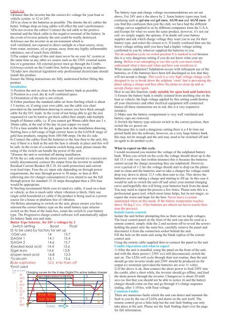
Charging curves for the 4 step Digital <strong>Pro</strong> active battery charger<br />
1<br />
1<br />
time x 10, with a minimum 1 hr max 12 hrs<br />
finish time<br />
start time<br />
TIME<br />
2<br />
2<br />
FLOAT 13.5 V<br />
3<br />
3<br />
4<br />
4<br />
FULL CURRENT AVAILABLE ON FLOAT FOR<br />
ON BOARD SUPPLY IN POWER PACK MODE<br />
100<br />
50<br />
0<br />
C<br />
H<br />
A<br />
R<br />
G<br />
E<br />
R<br />
%<br />
C<br />
U<br />
R<br />
R<br />
E<br />
N<br />
T<br />
2) If the above is ok, then connect the shore power to feed 230V into<br />
the combi, after a short while, the inverter should go offline, and feed<br />
the shore power through the inverter. Changeover is about 20 milli<br />
secs (so fast that you should not be able to notice it) and the battery<br />
charger should come on-line and go through it’s charge sequence<br />
ending, after 1-10 hrs, with float voltage.<br />
Common Faults:<br />
There are numerous faults which the unit can detect and transmit the<br />
fault to you by the use of LEDs and alarm on the unit itself. The<br />
remote control gives a little help but the real fault finding can only<br />
take place at the unit. Please see the fault finding chart over the page<br />
for full information.


