simrad dd15 - Chicago Marine Electronics
simrad dd15 - Chicago Marine Electronics
simrad dd15 - Chicago Marine Electronics

You also want an ePaper? Increase the reach of your titles
YUMPU automatically turns print PDFs into web optimized ePapers that Google loves.
Manual<br />
Simrad DD15<br />
Direct Drive<br />
English<br />
www.<strong>simrad</strong>-yachting.com<br />
A brand by Navico - Leader in <strong>Marine</strong> <strong>Electronics</strong>
MANUAL<br />
SIMRAD DD15<br />
Direct Drive<br />
20222303A<br />
English
Simrad DD15 Direct Drive<br />
About this document<br />
Rev Date Written by Checked by Approved by<br />
A<br />
06.04.06 NG IK ThH<br />
First edition<br />
© 2006 Simrad AS. All rights reserved.<br />
No part of this work covered by the copyright hereon may be reproduced or<br />
otherwise copied without prior permission from Simrad AS.<br />
The information contained in this document is subject to change without prior<br />
notice. Simrad AS shall not be liable for errors contained herein, or for incidental<br />
or consequential damages in connection with the furnishing, performance, or use<br />
of this document.<br />
2 20222303 / A
Introduction<br />
Contents<br />
1 SYSTEM DESCRIPTION...............................................5<br />
1.1 General .................................................................................................. 5<br />
1.2 How to use this manual.........................................................................6<br />
1.3 Performance ..........................................................................................7<br />
1.4 Compatibility in 12 Volts......................................................................8<br />
2 CONSTRUCTION .........................................................9<br />
2.1 Electric Motor .......................................................................................9<br />
2.2 Planetary gearbox..................................................................................9<br />
2.3 Electro magnetic clutch.......................................................................10<br />
3 INSTALLATION.........................................................11<br />
3.1 Mechanical mounting..........................................................................11<br />
Reducing noise and vibrations ...................................................12<br />
Feedback unit mounting.............................................................13<br />
Direct drive in combination with rack and pinion system .........15<br />
Direct drive in front of pedestal .................................................17<br />
3.2 Electrical connections .........................................................................18<br />
3.3 Test the system....................................................................................19<br />
4 MAINTENANCE .........................................................20<br />
5 TECHNICAL SPECIFICATIONS ..................................21<br />
Draglinks ....................................................................................22<br />
Spare Parts..................................................................................22<br />
20222303 / A 3
Simrad DD15 Direct Drive<br />
This page is intentionally left blank<br />
4 20222303 / A
System description<br />
1 SYSTEM DESCRIPTION<br />
1.1 General<br />
The DD15 Direct Drive is a very strong and compact autopilot<br />
drive and more efficient than hydraulic and most electromechanical<br />
autopilot drive units. It is powerful (the max. output<br />
torque of 150 Kgm is equivalent to 150 Kg force on the end of a<br />
1 meter steering tiller) and is build for 24 hours per day<br />
continuous operation with a total weight of only 12 Kgs. The<br />
combination of the flat wound (pancake) electric motor with the<br />
efficient planetary and spur gearbox results in an extremely<br />
efficient drive unit to keep the battery charging time to the<br />
minimum. The drive can be used on boats from 30 to 45 feet<br />
l.o.a. (or up to 150 Kgm rudder torque) equipped with a<br />
mechanical steering system that can be back driven. Due to the<br />
electro mechanical clutch, the direct drive can be back driven<br />
with the force of a finger tip leaving the mechanical steering as<br />
sensitive as without drive unit.<br />
The DD15 includes the Simrad RF300 Rudder Feedback unit<br />
with transmission link and 10 m (30 feet) of cable. It transforms<br />
the angular travel of the rudder to a digital signal read by the<br />
autopilot steering computer.<br />
Figure 1-1 Simrad DD15 Direct Drive (with RF300)<br />
20222303 / A 5
Simrad DD15 Direct Drive<br />
1.2 How to use this manual<br />
This manual is intended as a reference guide for correctly<br />
installing the Simrad DD15 Direct Drive.<br />
Please take time to read the manual to get a thorough<br />
understanding of the use of the drive and the connection to an<br />
autopilot system.<br />
Figure 1-2 Basic autopilot system<br />
This illustration shows the minimum number of components for<br />
a working autopilot configuration.<br />
6 20222303 / A
Construction<br />
1.3 Performance<br />
The performance table shows the relation between the consumed<br />
power and the output power. The “rudder torque midships” line<br />
shows the output torque against the needed amperage at<br />
midships rudder and the “rudder torque full rudder” line shows<br />
the output torque against the needed amperage at full rudder. The<br />
“hard over time” line shows the hard over time (time to travel<br />
72° of rudder travel) of the drive relative to the output torque.<br />
The table also presents the strength of the drive unit related to<br />
man power. The unit is much stronger than a human being and<br />
can last much longer. One should note however that when the<br />
unit is operated in the dark grey zone, the trim of the boat is not<br />
at its best and the sails should be adjusted to achieve lower<br />
rudder torques. The below table shows that the Simrad direct<br />
drive will steer the yacht even in the worst possible conditions.<br />
As the drive will mostly operate in the light grey zone but not<br />
continuously, the average power consumption on 12 volts is 2<br />
amps.<br />
[ HO-time ]<br />
24<br />
22<br />
light to medium steering forces,<br />
manageable for a helmsman for a few hours<br />
medium to high steering forces,<br />
manageable for a helmsman for a few minutes<br />
rudder torque midships<br />
hard over time<br />
[ Amp ]<br />
13<br />
12<br />
11<br />
20<br />
18<br />
16<br />
14<br />
high steering forces,<br />
not manageable by hand power<br />
rudder torque full rudder<br />
10<br />
9<br />
8<br />
7<br />
12<br />
6<br />
10<br />
5<br />
8<br />
4<br />
6<br />
3<br />
4<br />
2<br />
2<br />
1<br />
0<br />
0 5 10 15 20 25 30 35 40 45 50 55 60 65 70 75 80 85 90 95 100 105 110 115 120 125 130 135 140 145 150<br />
Drive output torque [ Kgm ]<br />
Figure 1-3 DD15 Direct Drive performance table<br />
20222303 / A 7
Simrad DD15 Direct Drive<br />
1.4 Compatibility in 12 Volts<br />
Autopilot computer<br />
12 Volt version.<br />
The following table shows the maximum rudder torques at<br />
amidships and full rudder that can be achieved with the Simrad<br />
direct drive in combination with the autopilot computer. The<br />
hard over time (HO-time) states the time it takes the drive to<br />
travel the full 72 degrees of rudder travel when the speed control<br />
of the autopilot is set to maximum speed.<br />
Max. Output<br />
(Amp.)<br />
Rudder torque<br />
amidships<br />
(Kgm)<br />
Rudder torque<br />
full rudder<br />
(Kgm)<br />
Simrad AC10 (J3000X) 12 73 140<br />
Simrad AC20 (J300X) 20 80 150<br />
Note<br />
Even if the AC10 Autopilot Computer is capable of driving the<br />
unit almost to its full power, the AC20 version will have the<br />
necessary extra power when the unit is operating to its extremes.<br />
8 20222303 / A
Construction<br />
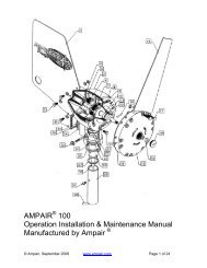
2 CONSTRUCTION<br />
This assembly drawing shows a cross section of the direct drive.<br />
The drive can be separated in 5 main parts: The electric motor,<br />
the two step spur gearbox, the planetary gearbox, the electromagnetic<br />
clutch and the final spur reduction gearbox. The<br />
Simrad direct drive has multiple advantages over existing<br />
integrated drive units. These advantages will be explained per<br />
section of the drive:<br />
2.1 Electric Motor<br />
The flat wound electric motor (pancake motor) used in the<br />
Simrad direct drive is carefully selected for this application.<br />
Pancake motors have multiple advantages over normal electric<br />
DC motors:<br />
• A large flat wound rotor to achieve a high starting toque and<br />
an immediate response to the autopilot speed control signal.<br />
• A motor efficiency of 72,5% to achieve a minimal power<br />
consumption and maximal mechanical power output<br />
(compared to max. 50% efficiency of a normal DC motor).<br />
• Compact main dimensions compared to achievable output.<br />
• Aluminum motor housing in stead of sheet steel plate to<br />
avoid corrosion.<br />
2.2 Planetary gearbox<br />
To achieve a correct rudder travel speed (hard over time) the<br />
electric motor has to be reduced in speed with a factor 750:1.<br />
Some autopilot drive producers use a worm reduction box, but<br />
the efficiency is extremely low as the gears rub each other. The<br />
Simrad direct drive uses a combination of a planetary gearbox<br />
and spur gear sets (one small gear and one big gear). The<br />
planetary gearbox has following advantages:<br />
20222303 / A 9
Simrad DD15 Direct Drive<br />
• The highest possible efficiency compared to any other<br />
gearbox.<br />
• All forces are equally spread over 3 gear teeth in stead of<br />
one allowing a much compacter and stronger solution.<br />
• The forces and torques from the motor to the output shaft<br />
remain in the center line of the drive unit, resulting in a<br />
higher efficiency and extremely reduces the loads on the<br />
housing and other internal parts.<br />
2.3 Electro magnetic clutch<br />
On the moment the mechanical steering system on the yacht is<br />
manually operated, the autopilot drive has to be disconnected<br />
from the steering system. This is achieved with the unique and<br />
patented electro-magnetic engagement clutch, controlled<br />
automatically by the autopilot computer. The solution is based<br />
on two electrically operated spring loaded clutch pins that<br />
engage and disengage the outer gear ring of the planetary gear<br />
step. This solution has multiple advantages over the existing<br />
friction plate clutches:<br />
• Less friction to back drive the unit.<br />
• Lower power consumption (1.2 Amp. at 12 Volt). When the<br />
clutch is not powered, it is disengaged.<br />
• The clutch doesn't wear in time.<br />
• More compact than any friction clutch.<br />
• When the autopilot is switched off, the helmsman is not<br />
suddenly confronted with the full rudder torque, but has to<br />
put load on the wheel to equalize the forces so the clutch can<br />
disengage, making the manual take over much safer.<br />
10 20222303 / A
Installation<br />
3 INSTALLATION<br />
3.1 Mechanical mounting<br />
The direct drive drives the rudder via a draglink to the existing<br />
tiller lever or quadrant or via a separate tiller lever. The length of<br />
the draglink and a separate tiller lever (if necessary) have to be<br />
specified when ordering. See the Direct Drive Specification<br />
Form (page 23) for available draglink lengths and tiller levers.<br />
The draglink part numbers are listed on page 22.<br />
The drive can be mounted behind or next to the rudderstock,<br />
driving the rudder directly or in front of the pedestal driving the<br />
rudder via the pedestal.<br />
The direct drive comes as standard with a 16 mm pin 165 mm from<br />
the center of the output lever. The pin can be moved to the 130 mm<br />
position from the center, but must be secured with Loctite.<br />
The direct drive uses “wide angle geometry”. The result of this is<br />
a 130° travel of the output lever and a 72° travel of the tiller<br />
lever( see Figure 3-2). To achieve an equal travel of the drive at<br />
port and starboard, the center point of the output lever needs an<br />
offset to the rudderstock centre. The offset depends on the used<br />
lever centers. Following table shows the correct offset distances:<br />
Operating centers in mm valid for 72° (2x36°) rudder travel.<br />
Output center Offset distance Tiller center<br />
130 106 200<br />
165 127 250<br />
Min. 300 - max 2000 mm<br />
Tiller<br />
center<br />
Draglink<br />
Tiller lever<br />
Offset<br />
Output lever<br />
165 mm<br />
130 mm<br />
Output<br />
center<br />
Figure 3-1 Mechanical mounting<br />
20222303 / A 11
Simrad DD15 Direct Drive<br />
A good installation check is to make sure that all end position<br />
points for the output lever and the tiller lever are in one line.<br />
Figure 3-2 Travel of tiller lever and output lever<br />
Reducing noise and vibrations<br />
The vibrations from the autopilot drive motor and gears are often<br />
amplified multiple times by the deck or hull. This noise can be<br />
dramatically decreased by using the special bolts, rubber washers<br />
and bushes one can find in the bag supplied with the drive unit.<br />
When mounted like in the below illustration, the vibrations will<br />
be limited to the absolute minimum and a smooth and silent<br />
installation is guaranteed.<br />
DIN912 M8x50<br />
Washer Ø8,5 x Ø16<br />
Rubber washer<br />
Drive unit<br />
Rubber washer<br />
Washer Ø8,5 x Ø25<br />
Nut DIN985 M8<br />
Mounting plate<br />
Figure 3-3 Reducing vibrations<br />
12 20222303 / A
Installation<br />
Feedback unit mounting<br />
Attached to the direct drive is a mounting bracket for the rudder<br />
feedback unit. The feedback unit and transmission link with<br />
mounting screws are supplied with the direct drive.<br />
- Set the rudder to amidships position.<br />
- Clamp the feedback bracket to the direct drive with a 90°<br />
angle to the output lever.<br />
- Set the feedback transmitter lever to center position by<br />
means of the alignment marks.<br />
- Attach the feedback unit to the bracket by using the supplied<br />
screws. With the rudder in amidships position make sure the<br />
transmitter lever and the output lever is in parallel and<br />
pointing in the same direction.<br />
- Attach one end of the transmission link to the output lever.<br />
- Attached the other end to the transmitter lever slot and make<br />
sure the link is in parallel with the mounting plate.<br />
Transmission link<br />
Output lever<br />
Outer slot<br />
Transmitter lever<br />
Alignment marks<br />
Rudder<br />
feedback<br />
bracket<br />
Figure 3-4 Feedback unit mounting<br />
20222303 / A 13
Simrad DD15 Direct Drive<br />
Examples of DD15 Mounting<br />
14 20222303 / A
Installation<br />
Direct drive in combination with rack and<br />
pinion system<br />
In principle the installation in combination with a rack and<br />
pinion system is the same as the standard installation except for<br />
the fact that the complete setup is rotated with the steering offset<br />
angle β.<br />
First install the rack and pinion system with the correct<br />
geometry, put the rudder amidships and find the line<br />
perpendicular to the tiller lever center line. Put the drive on a<br />
parallel line with an offset distance as in below table. Rotate the<br />
drive lever to the same offset angle as the steering system offset<br />
angle β and mount the draglink.<br />
Operating centers in mm valid for 72° (2x36°) rudder travel.<br />
Output center Offset distance Tiller center<br />
130 106 200<br />
165 127 250<br />
rudder<br />
stock<br />
pedestal<br />
direct drive<br />
tiller<br />
arm<br />
draglink<br />
stop plate<br />
output<br />
lever<br />
Figure 3-5 Drive unit in combination with rack and pinion system -<br />
side view<br />
20222303 / A 15
Simrad DD15 Direct Drive<br />
offset<br />
Figure 3-6 Drive unit in combination with rack and pinion system –<br />
top view<br />
16 20222303 / A
Installation<br />
Direct drive in front of pedestal<br />
When sufficient space around the rudder shaft isn’t available, the<br />
direct drive can be setup to drive the rudder via the pedestal.<br />
An extra extended output lever with 165 mm centers can be<br />
fitted to the pedestal down-shaft to be driven by the direct drive.<br />
The lever geometry between the drive and pedestal is a<br />
parallelogram of 165 mm. The pedestal offset angle has to be<br />
respected, so the whole parallelogram is rotated around the<br />
pedestal center with the offset angle.<br />
36°<br />
8°<br />
8°<br />
top view<br />
130<br />
165<br />
165<br />
64°<br />
64°<br />
Figure 3-7 Drive unit in front of pedestal<br />
20222303 / A 17
Simrad DD15 Direct Drive<br />
3.2 Electrical connections<br />
The connection of the Simrad direct drive to the autopilot<br />
computer is quite simple. The two 0.75 mm² red and black wires<br />
for the clutch have to be connected to the plus and minus of the<br />
autopilot clutch Drive Engage terminals. This will make sure<br />
that when the autopilot user engages the autopilot on the control<br />
unit, the clutch will engage and allow the autopilot motor to<br />
drive the steering system. The two heavy 2 mm² red and black<br />
wires have to be connected to the Solenoid – Motor terminals.<br />
Figure 3-8 Autopilot connection<br />
18 20222303 / A
Installation<br />
3.3 Test the system<br />
Note<br />
Before you can test the system, make sure following things are<br />
correct:<br />
• Solid rudder stops should be fitted limiting the rudder travel<br />
to an equal travel of 36 degrees from amidships to port and<br />
starboard.<br />
• Make sure all bolted parts (tiller pins, rose joints, draglinks,<br />
tiller arm, feedback, transmission link, etc) are firmly<br />
tightened and will not come loose even when exposed to<br />
heavy vibrations. Use Loctite when necessary.<br />
• Move the complete system from port to starboard making<br />
sure the rose joints don’t hit the output lever and tiller lever.<br />
• Make sure the drive output lever rotates equally<br />
approximately 65 degrees to both sides and there is no risk<br />
for the output lever to pass “over dead centre” so it can’t<br />
return to the initial position any more, blocking the system.<br />
Refer to the autopilot manual and perform the rudder calibration<br />
and test.<br />
Even if the ratio between the output lever of the drive unit and<br />
the rudder tiller is not linear, follow the instructions as written.<br />
If the drive doesn’t react to the electronics, test the drive by<br />
bypassing the electronics: Connect a plus and minus wire to the<br />
battery or fuse box and first connect the clutch, one should hear a<br />
click when connecting and disconnecting. With the clutch under<br />
power, connect power for a short time to the motor cables. The<br />
system should get in motion now. Don’t connect the cables too<br />
long as the drive will try to continue, even when the rudder stops<br />
are reached, with potential damage to the structure. If motion is<br />
detected, one can rule out the drive causing the malfunction.<br />
20222303 / A 19
Simrad DD15 Direct Drive<br />
4 MAINTENANCE<br />
The direct drive is “greased for life”, so it should not be opened.<br />
No maintenance is required except for periodic checks of all<br />
bolted connections. As the rudder system, the steering system<br />
and the autopilot drive are exposed to heavy vibrations (mainly<br />
by cruising on motor), all bolted connections should be yearly<br />
checked. The only parts that could wear in time are the ball<br />
joints in the draglink. These are easily exchangeable and<br />
available from Simrad.<br />
20 20222303 / A
Technical Specifications<br />
5 TECHNICAL SPECIFICATIONS<br />
Dimensions:............................................................See Figure 5-1<br />
Weight: ................................................................. 12 Kg (26.5 lb.)<br />
Motor voltage:......................................................................... 12V<br />
Clutch voltage: ........................................................................ 12V<br />
Average power consumption: ........................................... 2 Amps<br />
Output torque: .................................................................150 Kgm<br />
345 [13.5]<br />
321 [12.5]<br />
164 [6.4]<br />
140 [5.5]<br />
77 [3]<br />
10 [0.4]<br />
177 [6.9]<br />
Figure 5-1 DD15 Dimensional drawing<br />
20222303 / A 21
Simrad DD15 Direct Drive<br />
Figure 5-2 Rudder feedback bracket - Dimensions<br />
Draglinks<br />
44172088 Draglink DL3040 (300 [11,8”] - 400 [15,7”] mm)<br />
44172096 Draglink DL2030 (200 [7,9”] - 300 [11,8”] mm)<br />
44172104 Draglink DL4050 (400 [15,7”] - 500 [19,7”] mm)<br />
Spare Parts<br />
20193744 RF300 Rudder Feedback<br />
20193769 Transmission link<br />
Draglink ball joint<br />
22 20222303 / A
Technical Specifications<br />
output<br />
lever<br />
output<br />
centers<br />
20<br />
DIRECT DRIVE SPECIFICATION FORM<br />
direct<br />
drive<br />
65°(2x)<br />
273<br />
tiller pin<br />
16<br />
250<br />
200<br />
140<br />
The direct drive comes as standard with a 16mm pin in the 165 mm centers. The pin<br />
can be changed over to the 130 mm centers, but must be secured with LOCTITE.<br />
Max. diam. D<br />
(standard)<br />
specify draglink lenght<br />
(please cross the appropriate box)<br />
200-300mm (DL2030)<br />
300-400mm (DL3040)<br />
400-500mm (DL4050)<br />
Version 1.2<br />
500-600mm (DL5060)<br />
custom lenght ........mm<br />
include TLJPIN16<br />
specification of tiller arm locking mechanism<br />
if a key is present,<br />
specify dimensions<br />
key width b =<br />
key height h =<br />
M10<br />
if no key is present,<br />
cross below box<br />
for locking bolts<br />
include<br />
key angle a =<br />
2 off M10<br />
locking<br />
no keyway<br />
bolts<br />
special requirements / comments<br />
TLJ050 TLJ075 TLJ100 TLJ125<br />
h<br />
b<br />
a°<br />
2pcs M4<br />
locking<br />
bolt<br />
offset<br />
draglink<br />
min.300-max 2000 mm<br />
rudder<br />
shaft<br />
key<br />
specification of tiller arm<br />
60<br />
4xM10<br />
tiller<br />
center<br />
tiller<br />
arm<br />
36°(2x)<br />
Direct drive type I operating<br />
centres in mm valid for 72°<br />
(2x36°) rudder travel.<br />
output<br />
centers<br />
offset<br />
distance<br />
bore diameter = ...... mm<br />
please select the tillerarm<br />
by crossing the correct box<br />
tiller<br />
centers<br />
130 106 200<br />
165 127 250<br />
bore diam. tiller arm cross box<br />
- 50 mm TLJ050<br />
51-75mm TLJ075<br />
76-100mm TLJ100<br />
101-125mm TLJ125<br />
to include a tiller pin<br />
please cross below box<br />
20222303 / A 23
Simrad DD15 Direct Drive<br />
24 20222303 / A
DD15 Direct Drive manual EN, Doc.no.20222303, Rev.A