Connectors - Jetway Computer
Connectors - Jetway Computer
Connectors - Jetway Computer

Create successful ePaper yourself
Turn your PDF publications into a flip-book with our unique Google optimized e-Paper software.
Technical Manual<br />
Of<br />
Intel Cedar Trail Series CPU<br />
& NM10 Chipset<br />
Based<br />
Mini-ITX M/B<br />
NO.G03-NF9C-F<br />
Revision: 2.0<br />
Release date: December, 2011<br />
Trademark:<br />
* Specifications and Information contained in this documentation are furnished for information use only, and are<br />
subject to change at any time without notice, and should not be construed as a commitment by manufacturer.
Environmental Protection Announcement<br />
Do not dispose this electronic device into the trash while discarding. To minimize<br />
pollution and ensure environment protection of mother earth, please recycle.<br />
ii
TABLE OF CONTENT<br />
ENVIRONMENTAL SAFETY INSTRUCTION...........................................................................iv<br />
USER’S NOTICE .......................................................................................................................v<br />
MANUAL REVISION INFORMATION.......................................................................................v<br />
ITEM CHECKLIST .....................................................................................................................v<br />
CHAPTER 1 INTRODUCTION OF THE MOTHERBOARD<br />
1-1 FEATURE OF MOTHERBOARD................................................................................1<br />
1-2 SPECIFICATION .........................................................................................................2<br />
1-3 LAYOUT DIAGRAM....................................................................................................3<br />
CHAPTER 2 HARDWARE INSTALLATION<br />
2-1 JUMPER SETTING .....................................................................................................8<br />
2-2 CONNECTORS AND HEADERS................................................................................17<br />
2-2-1 CONNECTORS .............................................................................................17<br />
2-2-2 HEADERS .....................................................................................................19<br />
CHAPTER 3 INTRODUCING BIOS<br />
3-1 ENTERNING SETUP...................................................................................................28<br />
3-2 BIOS MENU SCREEN ................................................................................................29<br />
3-3 FUNCTION KEYS .......................................................................................................29<br />
3-4 GETTING HELP ..........................................................................................................30<br />
3-5 MENU BAR..................................................................................................................31<br />
3-6 MAIN MENU ................................................................................................................31<br />
3-7 ADVANCED MENU.....................................................................................................33<br />
3-8 CHIPSET MENU..........................................................................................................40<br />
3-9 BOOT MENU...............................................................................................................43<br />
3-10 SECURITY MENU .......................................................................................................44<br />
3-11 SAVE & EXIT MENU...................................................................................................45<br />
iii
Environmental Safety Instruction<br />
• Avoid the dusty, humidity and temperature extremes. Do not place the product in<br />
any area where it may become wet.<br />
• 0 to 60 centigrade is the suitable temperature. (The figure comes from the request<br />
of the main chipset)<br />
• Generally speaking, dramatic changes in temperature may lead to contact<br />
malfunction and crackles due to constant thermal expansion and contraction from<br />
the welding spots’ that connect components and PCB. <strong>Computer</strong> should go<br />
through an adaptive phase before it boots when it is moved from a cold<br />
environment to a warmer one to avoid condensation phenomenon. These water<br />
drops attached on PCB or the surface of the components can bring about<br />
phenomena as minor as computer instability resulted from corrosion and oxidation<br />
from components and PCB or as major as short circuit that can burn the<br />
components. Suggest starting the computer until the temperature goes up.<br />
• The increasing temperature of the capacitor may decrease the life of computer.<br />
Using the close case may decrease the life of other device because the higher<br />
temperature in the inner of the case.<br />
• Attention to the heat sink when you over-clocking. The higher temperature may<br />
decrease the life of the device and burned the capacitor.<br />
iv
USER’S NOTICE<br />
COPYRIGHT OF THIS MANUAL BELONGS TO THE MANUFACTURER. NO PART OF THIS MANUAL,<br />
INCLUDING THE PRODUCTS AND SOFTWARE DESCRIBED IN IT MAY BE REPRODUCED, TRANSMITTED<br />
OR TRANSLATED INTO ANY LANGUAGE IN ANY FORM OR BY ANY MEANS WITHOUT WRITTEN<br />
PERMISSION OF THE MANUFACTURER.<br />
THIS MANUAL CONTAINS ALL INFORMATION REQUIRED TO USE THIS MOTHER-BOARD SERIES AND WE<br />
DO ASSURE THIS MANUAL MEETS USER’S REQUIREMENT BUT WILL CHANGE, CORRECT ANY TIME<br />
WITHOUT NOTICE. MANUFACTURER PROVIDES THIS MANUAL “AS IS” WITHOUT WARRANTY OF ANY<br />
KIND, AND WILL NOT BE LIABLE FOR ANY INDIRECT, SPECIAL, INCIDENTIAL OR CONSEQUENTIAL<br />
DAMAGES (INCLUDING DAMANGES FOR LOSS OF PROFIT, LOSS OF BUSINESS, LOSS OF USE OF DATA,<br />
INTERRUPTION OF BUSINESS AND THE LIKE).<br />
PRODUCTS AND CORPORATE NAMES APPEARING IN THIS MANUAL MAY OR MAY NOT BE<br />
REGISTERED TRADEMARKS OR COPYRIGHTS OF THEIR RESPECTIVE COMPANIES, AND THEY ARE<br />
USED ONLY FOR IDENTIFICATION OR EXPLANATION AND TO THE OWNER’S BENEFIT, WITHOUT<br />
INTENT TO INFRINGE.<br />
Manual Revision Information<br />
Reversion Revision History Date<br />
2.0 Second Edition December, 2011<br />
Item Checklist<br />
Motherboard<br />
Motherboard User’s Manual<br />
DVD for motherboard utilities<br />
Cable(s)<br />
Back panel<br />
v
Chapter 1<br />
Introduction of the Motherboard<br />
1-1 Feature of Motherboard<br />
• Intel ® Cedar Trail series CPU and NM10 Chipset, with low power consumption never<br />
denies high performance<br />
• Support DDRIII 800/1066 MHz SO-DIMM (N2600 series only support 800 MHz)<br />
• Onboard Realtek RTL 8111E Gigabit Ethernet LAN<br />
• Integrated ALC662 2-channel HD audio CODEC<br />
• Support DirectX 9 Graphics<br />
• Integrated LVDS<br />
• Support RS232/422/485<br />
• Support Watch dog Technology<br />
• Support Smart Fan function<br />
• Compliance with ErP standard<br />
• Slim & fanless design, within 2cm height<br />
1
1-2 Specification<br />
Spec<br />
Description<br />
Design<br />
• Mini-ITX form factor 6 layers ; PCB size: 17.0 x17.0cm<br />
Chipset • Intel ® NM10 Express chipset<br />
Embedded CPU • Intel ® Cedar Trail series CPU<br />
• 2 * SO-DIMM DDRIII slots supports DDRIII 800/1066 MHz<br />
SO-DIMM , total maximum to 4GB<br />
Note:<br />
Memory Slot<br />
– N2600 series are with1 * SO-DIMM DDRIII slot for DDRIII 800<br />
MHz SO-DIMM , total maximum to 2GB<br />
– Support Small Outline DIMMs Raw Cards RC-B(1Rx8), and<br />
RC-F (2Rx8). Does not support RC-A (2Rx16), RC-C (1Rx16),<br />
RC-D (2Rx16 dual die), and RC-E(2Rx16)<br />
Storage<br />
• 1 * Serial ATAII (3Gb/s) connector<br />
• 2 * Serial ATAIII (6Gb/s) connectors<br />
• 1 * 32-bit PCI slot<br />
Expansion Slot • 1 * Mini-PCI E slot<br />
• 1 * CFast Storage card slot<br />
LAN<br />
• Integrated Realtek RTL8111E PCI-E Gigabit LAN<br />
• Support Fast Ethernet LAN function of providing<br />
10/100/1000Mbps Ethernet data transfer rate<br />
Audio<br />
• ALC 662 2-channel Audio Codec integrated<br />
• Audio driver and utility included<br />
BIOS<br />
• 16MB DIP Flash ROM<br />
Multi I/O<br />
• HDMI port connector x1<br />
• Serial port connector x1<br />
• USB 2.0 connector x3 and USB 2.0 header x2<br />
• RJ-45 LAN connector x1<br />
• Line out/Optical SPDIF_out connector<br />
• Front audio header x1<br />
2
• CDIN header x1<br />
• HDMI_SPDIF header x1<br />
• Parallel port header x1<br />
• VGA port header x1<br />
• LVDS1 header x 1 and INVERTER1 x 1 (Optional)<br />
• LVDS2 header x1 and INVERTER2 x 1<br />
• Serial port header x 3<br />
• RS422/RS485 header x1<br />
• GPIO header x1<br />
• Front panel header x1<br />
• 3-pin Power LED header x1<br />
• Speaker header x1<br />
• PS/2 Keyboard & mouse header x1<br />
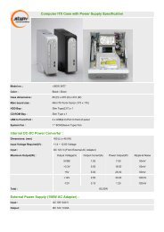
1-3 Layout Diagram<br />
Rear IO Diagram<br />
DC12V<br />
Power<br />
Connector<br />
HDMI<br />
Connector<br />
COM<br />
Connector<br />
USB<br />
RJ-45 LAN Port<br />
<strong>Connectors</strong><br />
USB<br />
Connector<br />
Line Out/<br />
Optical SPDIF_Out Connector<br />
Warning!<br />
The board has a DC 12V power connector in I/O back panel and an internal<br />
ATX12V power connector. User can only connect power supply to one of them.<br />
3
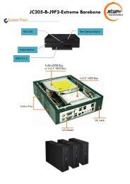
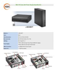
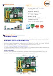
Motherboard Internal Diagram<br />
CPU FAN Header<br />
DC12V Power<br />
Connector<br />
(J1)<br />
HDMI<br />
Connector<br />
VGA Header<br />
LVDS Header<br />
(LVDS1)<br />
Intel CPU<br />
SO-DIMM1 Slot<br />
(Optional)<br />
COM<br />
Connector<br />
INVERTER1<br />
INVERTER 2<br />
SO-DIMM2 Slot<br />
SYSFAN1 Header<br />
USB<br />
<strong>Connectors</strong><br />
RJ-45 LAN<br />
Connector<br />
Line Out/Optical<br />
SPDIF_out Connector<br />
CDIN Header<br />
Parallel Header<br />
Gigabit LAN Chip<br />
GPIO Header<br />
LVDS Header<br />
(LVDS2)<br />
Intel NM10<br />
Chipset<br />
TX-RXCOM1<br />
SATAII Port<br />
(SATA1)<br />
KB/MS Header<br />
Speaker Header<br />
CFast Card Slot<br />
Power LED Header<br />
SATAIII Ports<br />
(SATA3/SATA4)<br />
Audio Chip<br />
Front Panel Header<br />
SYSFAN2 Header<br />
Font Panel<br />
Serial Port Headers PCI Slot<br />
Audio Header<br />
Mini PCI-E Slot<br />
USB Headers<br />
SPDIF out Header<br />
Note! When installing only one SODIMM to the board, please always install it in SODIMM2 slot,<br />
otherwise system won’t start.<br />
4
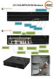
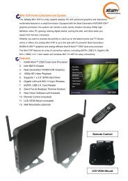
Motherboard Jumper Position<br />
JP2<br />
(Optional)<br />
JP9<br />
(Optional)<br />
JP13<br />
JP14<br />
JP1<br />
JP3<br />
(Optional)<br />
JP12<br />
JP17<br />
JBAT<br />
JP6<br />
JP16<br />
JP5<br />
JP15<br />
JP7<br />
Note: The diagrams in the manual serve illustration purpose only. SODIMM1, LVDS1 header,<br />
INVERTER2 and Jumper JP2 ,JP3 & JP9 are only optional with specific modesl. Please refer to<br />
the product purchased for actual specification.<br />
5
Jumper<br />
Jumper Name Description<br />
JBAT CMOS RAM Clear Function Setting 3-Pin Block<br />
JP1 USB 1/2 Power On Function Setting 3-Pin Block<br />
JP5 USB 3/4 Power On Function Setting 3-Pin Block<br />
JP2 (Optional) LVDS1 VCC 5V/3.3V Select 3-Pin Block<br />
JP3 (Optional) INVERTER1 VCC 12V/5V Select 3-Pin Block<br />
JP13 LVDS2 VCC 5V/3.3V Select 3-Pin Block<br />
JP12 INVERTER2 VCC 12V/5V Select 3-Pin Block<br />
JP14 COM1 Header Pin9 Function Select 6-Pin Block<br />
JP7 COM2 Header Pin9 Function Select 6-Pin Block<br />
JP15 COM3 Header Pin9 Function Select 6-Pin Block<br />
JP16 COM4 Header Pin9 Function Select 6-Pin Block<br />
JP17 COM4 RS232/485/422 Function Select 6-Pin Block<br />
COPEN Case Open Message Display Function 2-Pin Block<br />
JP6 MINIPCIE POWER SB3.3V/3.3V Select 3-Pin Block<br />
JP9 (Optional) LVDS1 Panel Resolution Type Select 8-Pin Block<br />
<strong>Connectors</strong><br />
Connector Name Description<br />
J1 DC12V In Power Connector 1-DC Jack<br />
J2 ATX 12V Type Power Connector 4-Pin Block<br />
HDMI High-Definition Multimedia Interface 10-pin Connector<br />
COM1 Serial Port Connector 9-Pin Male<br />
USB1 USB Port Connector 4-Pin Connector<br />
USB2 USB Port Connector x2 4-Pin Connector<br />
LAN1 RJ-45 LAN Connector 8-Pin Connector<br />
HP_SPDIF1 Line Out /Optical SPDIF Out Connector 1-Phone Jack<br />
PWOUT2 Power Out Connector 4-Pin Connector<br />
SATA1 SATAII Connector 7-Pin Connector<br />
SATA3/SATA4 Serial ATAIII Connector<br />
7-Pin Connector<br />
6
Headers<br />
Header Name Description<br />
FP_AUDIO1 Front Panel Audio Header 9-Pin Block<br />
CDIN1 CD Audio-In Header 4-pin Block<br />
SPDIF SPDIF Out header 2-pin Block<br />
PARALLEL Parallel Header 25-Pin Block<br />
VGA1 Video Graphic Attach Header 15-Pin Block<br />
LVDS1(optional)/ LVDS Header<br />
32-Pin Block<br />
LVDS2<br />
INVERTER1(optional)/ LVDS Inverter<br />
7-Pin Block<br />
INVERTER2<br />
SPEAK Speaker Header 4-pin Block<br />
PWRLED Power LED 3-pin Block<br />
JW_FP<br />
Front Panel Header(PWR LED/ 9-Pin Block<br />
HD LED/ /Power Button /Reset)<br />
KBMS PS/2 Keyboard/Mouse Header 6-Pin Block<br />
COM2, COM3, COM4 Serial Port Header<br />
9-Pin Block<br />
TX-RX RS 232/422/485 port header 4-Pin Block<br />
USB3; USB4 UBS Headers 9-Pin Block<br />
CPUFAN,SYSFAN1,S Fan Speed Headers<br />
3-Pin Block<br />
YSFAN2<br />
GPIO_CON GPIO Header 10-Pin<br />
7
Chapter 2<br />
Hardware Installation<br />
2-1 Jumper Setting<br />
(1) JBAT (3-pin): Clear CMOS<br />
JBAT<br />
JBAT<br />
1 3<br />
1-2 closed: Normal<br />
(2) JP1 (3-pin): USB 1/2 Power On Function Setting<br />
1 3<br />
2-3 closed : Clear CMOS<br />
JP1<br />
1<br />
1-2 closed : USB 1/2 Power on Disabled<br />
3<br />
JP1<br />
1<br />
3<br />
2-3 closed: USB 1/2 Power on Enabled(default)<br />
8
(3) JP5 (3-pin): USB 3/4 Power On Function Setting<br />
JP5<br />
1 3<br />
1-2 closed : USB 3/4 Power on Disabled<br />
JP5<br />
1 3<br />
(4) JP2 (3-pin): LVDS1 VCC 5V/3.3V Function Setting<br />
2-3 closed: USB 3/4 Power on Enabled(default)<br />
JP2<br />
3<br />
1<br />
1-2 closed: LVDS1 VCC 5V(default)<br />
JP2<br />
3<br />
1<br />
2-3 closed : LVDS1 VCC 3.3V<br />
* Note: Jumper JP2 is only optional for model with LVDS1 header.<br />
9
(5) JP3 (3-pin): INVERTER1 VCC 12V/5V Select<br />
JP3<br />
JP3<br />
3<br />
1<br />
3<br />
1<br />
1-2 closed:Inverter1 VCC=12V (default) 2-3 closed:Inverter1 VCC=<br />
* Note: Jumper JP3 is only optional for model with INVERTER1 header.<br />
(6) JP13 (3-pin): LVDS2 VCC 5V/3.3V Function Setting<br />
JP13<br />
3<br />
1<br />
1-2 closed: LVDS2 VCC 5V(default)<br />
JP13<br />
3<br />
1<br />
2-3 closed : LVDS2 VCC 3.3V<br />
10
(7) JP12 (3-pin): INVERTER2 VCC 12V/5V Select<br />
JP12<br />
JP12<br />
(8) JP14 (6-pin): COM1 Pin9 Function Select<br />
3<br />
3<br />
1<br />
1<br />
1-2 closed:Inverter2 VCC=12V (default) 2-3 closed:Inverter2 VCC=5V<br />
JP14<br />
1-2 closed: RS232<br />
1<br />
3-4 closed : +12V<br />
1<br />
5-6 closed : +5V<br />
1<br />
11
(9) JP7 (6-pin): COM2 Pin9 Function Select<br />
JP7<br />
1<br />
1<br />
1<br />
1-2 closed: RS232<br />
(10) JP15 (6-pin): COM3 Pin9 Function Select<br />
3-4 closed : +12V<br />
5-6 closed : +5V<br />
JP15<br />
1-2 closed: RS232<br />
1<br />
3-4 closed : +12V<br />
1<br />
5-6 closed : +5V<br />
1<br />
12
(11) JP16 (6-pin): COM4 Pin9 Function Select<br />
JP16<br />
1<br />
1-2 closed: RS232 3-4 closed : +12V 5-6 closed : +5V<br />
(12) JP17 (6-pin): COM4 RS232/485/422 Function Select<br />
JP17<br />
1<br />
1<br />
1<br />
1-2 closed: RS232<br />
3-4 closed : RS485<br />
5-6 closed : RS422<br />
13
(13)COPEN (2-pin): Case Open Message Display function select<br />
COPEN<br />
1-2 Open: Normal<br />
1-2 Short: Case Open<br />
Case Open Display Function<br />
Pin 1-2 shorted: Case open display function enabled. In this case if you case is<br />
removed, next time when you restart your computer a message will be displayed<br />
onscreen to inform you of this.<br />
(14) JP6 (3-pin): Mini PCI-E Power SB 3.3V/3.3V Function Select<br />
JP6<br />
3<br />
JP6 3<br />
1<br />
1<br />
1-2 closed:<br />
MINI PCI-E Power= VCC 3.3V<br />
2-3 closed:<br />
MINI PCI-E Power=3VSB<br />
14
(15) JP9 (8-pin): LVDS1 Panel Resolution Select<br />
2 8<br />
User can select Panel resolution by jumper settings. There are two basic setting<br />
modes:<br />
• Short: in which user can close pin 1-pin2, pin3-pin4, pin5-pin6, pin7-pin8<br />
respectively;<br />
• Open: in which user leave jumper hat just in pin 2, pin4, pin6 or pin8.<br />
Jumper Setting Description Panel Resolution Color Depth<br />
2<br />
1<br />
2<br />
1<br />
2<br />
1<br />
2<br />
1<br />
Pin 1-2: Short<br />
Pin 3-4: Short<br />
Pin 5-6: Short<br />
Pin 7-8: Short<br />
Pin 1-2: Open<br />
Pin 3-4: Short<br />
Pin 5-6: Short<br />
Pin 7-8: Short<br />
Pin 1-2: Short<br />
Pin 3-4: Open<br />
Pin 5-6: Short<br />
Pin 7-8: Short<br />
Pin 1-2: Open<br />
Pin 3-4: Open<br />
Pin 5-6: Short<br />
Pin 7-8: Short<br />
Pin1<br />
7<br />
640 x 480 @ 60Hz 18-bit<br />
800 x 600 @ 60Hz 18-bit<br />
1024 x 600 @ 60Hz 18-bit<br />
1024 x 768 @ 60Hz 24-bit<br />
15
2<br />
1<br />
2<br />
1<br />
2<br />
1<br />
2<br />
1<br />
2<br />
1<br />
2<br />
1<br />
2<br />
1<br />
2<br />
1<br />
2<br />
1<br />
2<br />
1<br />
2<br />
1<br />
Pin 1-2: Short<br />
Pin 3-4: Short<br />
Pin 5-6: Open<br />
Pin 7-8: Short<br />
Pin 1-2: Open<br />
Pin 3-4: Short<br />
Pin 5-6: Open<br />
Pin 7-8: Short<br />
Pin 1-2: Short<br />
Pin 3-4: Open<br />
Pin 5-6: Open<br />
Pin 7-8: Short<br />
Pin 1-2: Open<br />
Pin 3-4: Open<br />
Pin 5-6: Open<br />
Pin 7-8: Short<br />
Pin 1-2: Short<br />
Pin 3-4: Short<br />
Pin 5-6: Short<br />
Pin 7-8: Open<br />
Pin 1-2: Open<br />
Pin 3-4: Short<br />
Pin 5-6: Short<br />
Pin 7-8: Open<br />
Pin 1-2: Short<br />
Pin 3-4: Open<br />
Pin 5-6: Short<br />
Pin 7-8: Open<br />
Pin 1-2: Open<br />
Pin 3-4: Open<br />
Pin 5-6: Short<br />
Pin 7-8: Open<br />
Pin 1-2: Short<br />
Pin 3-4: Short<br />
Pin 5-6: Open<br />
Pin 7-8: Open<br />
Pin 1-2: Open<br />
Pin 3-4: Short<br />
Pin 5-6: Open<br />
Pin 7-8: Open<br />
Pin 1-2: Short<br />
Pin 3-4: Open<br />
Pin 5-6: Open<br />
Pin 7-8: Open<br />
1280 x 720 @ 60Hz 18-bit<br />
800 x 480 @ 60Hz 18-bit<br />
1366 x 768 @ 60Hz 18-bit<br />
1440 x 900 @ 60Hz 18-bit<br />
1366 x 768 @ 60Hz 24-bit<br />
1440 x 900 @ 60Hz 24-bit<br />
1280 x 1024 @ 60Hz 24-bit<br />
1440 x 1050 @ 60Hz 24-bit<br />
1600 x 900 @ 60Hz 24-bit<br />
1680 x 1050 @ 60Hz 24-bit<br />
1600 x 1200 @ 60Hz 24-bit<br />
16
2<br />
1<br />
Pin 1-2: Open<br />
Pin 3-4: Open<br />
Pin 5-6: Open<br />
Pin 7-8: Open<br />
1920 x 1080 @ 60Hz 24-bit<br />
* Note: Jumper JP9 is only optional for model with LVDS1 header.<br />
2-2 <strong>Connectors</strong> and Headers<br />
2-2-1 <strong>Connectors</strong><br />
(1) Rear I/O <strong>Connectors</strong><br />
DC12V<br />
Power<br />
Connector<br />
HDMI<br />
Connector<br />
COM<br />
Connector<br />
USB<br />
<strong>Connectors</strong><br />
RJ-45 LAN Port<br />
USB<br />
Connector<br />
Line Out/<br />
Optical SPDIF_Out Connector<br />
17
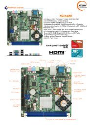
(2) Serial-ATA Port connector: SATA1, SATA3, SATA4<br />
SATA1 connector is an SATAII connector that supports SATA 3Gb/s<br />
specification. SATA3 and SATA4 connectors are SATAIII connectors that<br />
support SATA 6Gb/s specification.<br />
Pin No. Definition<br />
1 GND<br />
2 TXP<br />
3 TXN<br />
4 GND<br />
5 RXN<br />
6 RXP<br />
7 GND<br />
(3) ATX12V Type Power Connector (4-pin block):J2<br />
Pin1<br />
Pin No. Definition<br />
1 GND<br />
2 GND<br />
3 +12V<br />
4 +12V<br />
18
2-2-2 Headers<br />
(1) Front panel audio (9-pin): FP_AUDIO1<br />
GND<br />
NC<br />
NC<br />
NC<br />
AUDIO1<br />
Pin 1<br />
2<br />
10<br />
9<br />
MIC2-L<br />
MIC2-R<br />
LI NE OUT2-R<br />
NC<br />
LINE OUT2-L<br />
Line-Out, MIC Headers<br />
(2) CD AUDIO-In Header (4-pin): CDIN1<br />
CD-R<br />
GND<br />
GND<br />
CD-L<br />
Pin1<br />
19
(3) HDMI-SPDIF Out header (2-pin): SPDIF<br />
HDMI_SPDIF_OUT<br />
GND<br />
1<br />
2<br />
HDMI_SPDIF Header<br />
(4) VGA Header (15-pin): VGA1<br />
VSYNC<br />
SMBUS-DATE<br />
GND<br />
GND<br />
GND<br />
NC<br />
GREEN<br />
Pin2<br />
Pin1<br />
SMBUS_CLK<br />
HSYNC<br />
NC<br />
VCC VGA<br />
GND<br />
GND<br />
BLUE<br />
RED<br />
20
(5) 24-bit LVDS Header (32-pin): LVDS1 (Optional)<br />
Pin 32<br />
Pin31<br />
Pin 2 Pin 1<br />
LVDS1 Header<br />
Pin NO. Pin Define Pin NO. Pin Define<br />
Pin 1 LVDSB_DATAN3 Pin 2 LVDSB_DATAP3<br />
Pin 3 LVDS_CLKBN Pin 4 LVDS_CLKBP<br />
Pin 5 LVDSB_DATAN2 Pin 6 LVDSB_DATAP2<br />
Pin 7 LVDSB_DATAN1 Pin 8 LVDSB_DATAP1<br />
Pin 9 LVDSB_DATAN0 Pin 10 LVDSB_DATAP0<br />
Pin 11 LVDS_DDC_DATA Pin 12 LVDS_DDC_CLK<br />
Pin 13 GND Pin 14 GND<br />
Pin 15 GND Pin 16 GND<br />
Pin 17 NC/LVDSA_DATAP3 Pin 18 NC/LVDSA_DATAN3<br />
Pin 19 LVDS_CLKAP Pin 20 LVDS_CLKAN<br />
Pin 21 LVDSA_DATAP2 Pin 22 LVDSA_DATAN2<br />
Pin 23 LVDSA_DATAP1 Pin 24 LVDSA_DATAN1<br />
Pin 25 LVDSA_DATAP0 Pin 26 LVDSA_DATAN0<br />
Pin 27 PVDD Pin 28 PVDD<br />
Pin 29 PVDD Pin 30 PVDD<br />
Pin 31 GND Pin 32 GND<br />
21
(6) 18-bit LVDS Header (32-pin): LVDS2<br />
Pin 32<br />
Pin31<br />
Pin 2 Pin 1<br />
LVDS2 Header<br />
Pin NO. Pin Define Pin NO. Pin Define<br />
Pin 1 NC Pin 2 NC<br />
Pin 3 NC Pin 4 NC<br />
Pin 5 NC Pin 6 NC<br />
Pin 7 NC Pin 8 NC<br />
Pin 9 NC Pin 10 NC<br />
Pin 11 LVDS_DDC_DATA Pin 12 LVDS_DDC_CLK<br />
Pin 13 GND Pin 14 GND<br />
Pin 15 GND Pin 16 GND<br />
Pin 17 NC/LVDSA_DATAP3 Pin 18 NC/LVDSA_DATAN3<br />
Pin 19 LVDS_CLKAP Pin 20 LVDS_CLKAN<br />
Pin 21 LVDSA_DATAP2 Pin 22 LVDSA_DATAN2<br />
Pin 23 LVDSA_DATAP1 Pin 24 LVDSA_DATAN1<br />
Pin 25 LVDSA_DATAP0 Pin 26 LVDSA_DATAN0<br />
Pin 27 PVDD Pin 28 PVDD<br />
Pin 29 PVDD Pin 30 PVDD<br />
Pin 31 GND Pin 32 GND<br />
22
(7) LVDS Inverter Header (7-pin): INVERTER1 (Optional)<br />
Pin 1<br />
INVERTER1<br />
(8) LVDS Inverter Header (7-pin): INVERTER2<br />
Pin No. Definition<br />
1 VCC<br />
2 VCC<br />
3 GND<br />
4 GND<br />
5 Backlight<br />
6 GND<br />
7 Brightness<br />
Pin 1<br />
INVERTER2<br />
Pin No. Definition<br />
1 VCC<br />
2 VCC<br />
3 GND<br />
4 GND<br />
5 Backlight<br />
6 GND<br />
7 Brightness<br />
23
(9) Speaker Header (4-pin): SPEAK<br />
This 4-pin header connects to the case-mounted speaker. See the figure below.<br />
(10) Power LED Header (3-pin): PWR LED<br />
The Power LED is light on while the system power is on. Connect the Power LED<br />
from the system case to this pin header.<br />
Pin 1<br />
SPEAK<br />
Pin 1<br />
PWRLED<br />
VCC<br />
NC<br />
NC<br />
SPEAK<br />
VCC<br />
GND<br />
GND<br />
(11) Front Panel Header (9-pin): JW-FP<br />
JW FP<br />
PWR LED<br />
PWRBTN<br />
PWRLED-<br />
PWRLED+<br />
GND<br />
PWRBTN<br />
Pin 1<br />
NC<br />
RSTSW<br />
GND<br />
HDDLED-<br />
HDDLED+<br />
HDLED<br />
RESET<br />
24
(12) PS/2 Keyboard & Mouse Header (6-pin): KBMS<br />
MS CLK<br />
VCC<br />
MS_DATA<br />
KB_DATA<br />
GND<br />
KB CLK<br />
Pin1<br />
(13) Serial Port Header (9-pin): COM2, COM3, COM4<br />
RI<br />
CTS<br />
RTS<br />
DSR<br />
Pin6<br />
Pin1<br />
Pin5<br />
GND<br />
DTR<br />
TXD<br />
RXD<br />
DCD<br />
Serial COM Port 9-pin Block<br />
25
(14) RS422/485 Header (4-pin): TX-RX<br />
RXDN<br />
TXDN<br />
Pin 1<br />
2<br />
RXDP<br />
TXDP<br />
(15) USB Port Headers (9-pin): USB3, USB4<br />
NC<br />
GND<br />
+DATA<br />
-DATA<br />
VCC<br />
Pin 1<br />
GND<br />
+DATA<br />
-DATA<br />
VCC<br />
(16)FAN Speed Headers (3-pin): CPUFAN1, SYSFAN1, SYSFAN2<br />
Pin1: GND<br />
Pin2: +12V fan power<br />
Pin3: Fan Speed<br />
26
CPUFAN1<br />
1 3<br />
SYSFAN1 1<br />
3<br />
SYSFAN2<br />
3<br />
1<br />
(17) GPIO Header (10-pin): GPIO_CON<br />
VCC<br />
GP37<br />
GP35<br />
GP33<br />
GP31<br />
10<br />
9<br />
2<br />
Pin 1<br />
GND<br />
GP36<br />
GP34<br />
GP32<br />
GP30<br />
27
Chapter 3<br />
Introducing BIOS<br />
Notice!<br />
The BIOS options in this manual are for reference only. Different<br />
configurations may lead to difference in BIOS screen and BIOS<br />
screens in manuals are usually the first BIOS version when the board is<br />
released and may be different from your purchased motherboard.<br />
Users are welcome to download the latest BIOS version form our<br />
official website.<br />
The BIOS is a program located on a Flash Memory on the motherboard. This program<br />
is a bridge between motherboard and operating system. When you start the computer,<br />
the BIOS program will gain control. The BIOS first operates an auto-diagnostic test<br />
called POST (power on self test) for all the necessary hardware, it detects the entire<br />
hardware device and configures the parameters of the hardware synchronization.<br />
Only when these tasks are completed done it gives up control of the computer to<br />
operating system (OS). Since the BIOS is the only channel for hardware and software<br />
to communicate, it is the key factor for system stability, and in ensuring that your<br />
system performance as its best.<br />
3-1 Entering Setup<br />
Power on the computer and by pressing immediately allows you to enter Setup.<br />
If the message disappears before your respond and you still wish to enter Setup,<br />
restart the system to try again by turning it OFF then ON or pressing the “RESET”<br />
button on the system case. You may also restart by simultaneously pressing ,<br />
and keys. If you do not press the keys at the correct time and the<br />
system does not boot, an error message will be displayed and you will again be asked<br />
to<br />
Press<br />
to enter Setup<br />
28
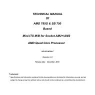
3-2 BIOS Menu Screen<br />
The following diagram show a general BIOS menu screen:<br />
Menu Bar<br />
General Help Items<br />
Menu Items<br />
Current Setting Value<br />
Function Keys Instruction<br />
3-3 Function Key<br />
In the above BIOS Setup main menu, you can see several options. We will explain<br />
these options step by step in the following pages of this chapter, but let us first see a<br />
short description of the function keys you may use here:<br />
29
• Press←→ (left, right) to select screen;<br />
• Press ↑↓ (up, down) to choose the item you want to confirm or to modify in the<br />
main menu.<br />
• Press to select.<br />
• Press / key when you want to modify the BIOS parameters for the active<br />
option.<br />
• [F1]: Press to general help information.<br />
• [F2]: Press to load previous value.<br />
• [F3]: Press to load optimized defaults.<br />
• [F4]: Save and Reset.<br />
• Press to exit from BIOS Setup.<br />
3-4 Getting Help<br />
Main Menu<br />
The on-line description of the highlighted setup function is displayed at the top right<br />
corner the screen.<br />
Status Page Setup Menu/Option Page Setup Menu<br />
Press [F1] to pop up a small help window that describes the appropriate keys to use<br />
and the possible selections for the highlighted item. To exit the Help Window, press<br />
.<br />
30
3-5 Menu Bar<br />
There are six menu bars on top of BIOS screen:<br />
Main<br />
To change system basic configuration<br />
Advanced<br />
To change system advanced configuration<br />
Chipset<br />
To change chipset configuration<br />
Boot<br />
To change boot settings<br />
Security<br />
Password settings<br />
Save & Exit<br />
Save setting, loading and exit options.<br />
User can press the ←/→ (left, right) arrow key on the keyboard to switch from menu<br />
bar. The selected one is highlighted.<br />
3-6 Main Menu<br />
Main menu screen includes some basic system information. Highlight the item and<br />
then use the / key or numerical keyboard keys to select the value you want in<br />
each item.<br />
31
System Date<br />
Set the date. Please use [TAB] to switch between data elements.<br />
System Time<br />
Set the time. Please use [TAB] to switch between time elements.<br />
32
3-7 Advanced Menu<br />
Scroll down to view more setting items…<br />
33
Launch External PxE OpROM/Launch LAN1 PXE OpROM<br />
Use this item to enable or disable boot option for legacy network devices.<br />
Launch Storage OpROM<br />
Use this item to enable or disable boot option for legacy mass storage devices with<br />
option ROM.<br />
Onboard LAN 1 Controller<br />
Use this item to enable or disable PCI Express root port 1.<br />
SATA 3.0 Controller<br />
Use this item to enable or disable SATA 3.0 controller.<br />
Configure SATA 3.0 as<br />
Use this item to select an operative mode for SATA 3.0 controller. The optional<br />
settings are: [IDE Mode]; [AHCI Mode].<br />
ERP Function<br />
Use this item to enable or disable ERP function for this board.<br />
► PCI Subsystem Settings<br />
Press [Enter] to enter and make settings for the following sub-items:<br />
PCI ROM Priority<br />
In the case of multiple option ROMs(Legacy and EFI compatible), specifies what<br />
PCI option ROM to launch. The optional settings: [Legacy ROM]; [EFI Compatible<br />
ROM].<br />
PCI Common Settings:<br />
PCI Latency Timer<br />
Use this item to set value to be programmed into PCI latency timer register.<br />
VGA Palette Snoop<br />
34
Use this item to enable or disable VGA palette register snooping.<br />
PERR# Generation<br />
Use this item to enable or disable PCI device to generate PERR#.<br />
SERR# Generation<br />
Use this item to enable or disable PCI device to generate SERR#.<br />
► ACPI Settings<br />
ACPI Sleep State<br />
Use this item to select the highest ACPI sleep state the system will enter when the<br />
suspend button is pressed.<br />
The optional settings are: [S1(CPU Stop Clock)]; [S3 (Suspend to ROM)].<br />
► Wakeup Function Settings<br />
Wake System with Fixed Time<br />
Use this item to enable or disable system wake on alarm event. When set as<br />
[Enabled], system will wake on the hour/min/sec specified.<br />
PS2 KB/MS Wakeup<br />
Use this item to enable or disable PS2 KB/MS wakeup function. This function is<br />
only supported when ERP function is set as [Disabled].<br />
PCI PME Wakeup<br />
Use this item to enable or disable S3/S4/S5 PCI PME wakeup. This function is<br />
only supported when ERP function is set as [Disabled].<br />
► CPU Configuration<br />
Hyper-Threading<br />
The optional settings are: [Disabled]; [Enabled].Set as [Enabled] for Windows XP<br />
and Linux (OS optimized for Hyper-Threading Technology) and [Disabled] for<br />
35
other OS (OS not optimized for Hyper-Threading Technology).<br />
Execute Disable Bit<br />
The optional settings are: [Disabled]; [Enabled].<br />
Limit CPUID Maximum<br />
The optional settings are: [Disabled]; [Enabled].<br />
This item should be set as [Disabled] for Windows XP.<br />
► SATA Configuration<br />
SATA Controller(s)<br />
The optional settings are: [Disabled]; [Enabled].<br />
Configure SATA as<br />
The optional settings are: [IDE]; [AHCI].<br />
► USB Configuration<br />
Legacy USB Support<br />
The optional settings are: [Auto]; [Disabled]; [Enabled].<br />
EHCI Hand-off<br />
The optional settings are: [Disabled]; [Enabled].<br />
USB Transfer time-out<br />
Use this item to set the time-out value for control, bulk, and interrupt transfers.<br />
Device reset time-out<br />
Use this item to set USB mass storage device start unit command time-out.<br />
Device power-up delay<br />
Use this item to set maximum time the device will take before it properly reports<br />
itself to the host controller. ‘Auto’ uses default value: for a root port it is 100 ms, for<br />
a hub port the delay is taken from hub descriptor. The optional settings: [Auto];<br />
36
[Manual].Select [Manual] you can set value for the following sub-item:<br />
Device Power-up delay in seconds, the delay range in from 1 to 40 seconds in<br />
one second increments.<br />
► Super I/O Configuration<br />
► COM1 Port Configuration/ COM2 Port Configuration<br />
Press [Enter] to make settings for the following items:<br />
Serial Port<br />
Use this item to enable or disable serial port (COM).<br />
Change Settings<br />
Use this item to select an optimal setting for super IO device.<br />
► Parallel Port Configuration<br />
Press [Enter] to make settings for the following items:<br />
Parallel Port<br />
Use this item to enable or disable parallel port (LPT/LPTE).<br />
Change Settings<br />
Use this item to select an optimal setting for super IO device.<br />
Device Mode<br />
Use this item to change the printer port mode.<br />
PS2 KB/MS Connect<br />
Use this item to set PS2 connect primary device. The optional settings are: [Keyboard<br />
First]; [Mouse First].<br />
Case Open Detect<br />
To detect if the case has bee opened or not.The optional settings are: [Enabled];<br />
[Disabled].<br />
37
► PC Health Status<br />
Press [Enter] to view hardware health status.<br />
► Second Super I/O Configuration<br />
► COM3 Port Configuration<br />
Press [Enter] to make settings for the following items:<br />
Serial Port<br />
Use this item to enable or disable serial port (COM).<br />
Change Settings<br />
Use this item to select an optimal setting for super IO device.<br />
► COM4 Port Configuration<br />
Press [Enter] to make settings for the following items:<br />
Serial Port<br />
Use this item to enable or disable serial port (COM).<br />
Change Settings<br />
Use this item to select an optimal setting for super IO device.<br />
Serial Port Mode Select<br />
The optional settings are: [RS232]; [RS422/RS485].<br />
► Clock Generator Configuration<br />
Clockgen Spread Spectrum<br />
Use this item to enable or disable spread spectrum function.<br />
IO Output Voltage<br />
Use this item to set IO output voltage.<br />
► Voltage Configuration<br />
DIMM Voltage<br />
The optional settings are: [Default]; [+50mV]; [+100mV]; [+150mV].<br />
38
► WatchDog Configuration<br />
WatchDog Timer Control<br />
Use this item to enable or disable WatchDog Timer Control. When set as<br />
[Enabled], the following sub-items shall appear:<br />
WatchDog Timer Value<br />
User can set a value in the range of 4 to 255.<br />
WatchDog Timer Unit<br />
The optional settings are: [Second];[Minute].<br />
► Shutdown Temperature Configuration<br />
Use this item to select system shutdown temperature.<br />
► PPM Configuration<br />
Use this item to set PPM configuration parameters. Press [Enter] to make settings<br />
for the following sub-items:<br />
EIST<br />
Use this item to enable or disable Intel Speed Step.<br />
CPU C-State Report<br />
Use this item to enable or disable CPUC-state report to OS.<br />
Enhanced C-state<br />
Use this item to enable or disable enhanced CPU C-state.<br />
► SmartFan Configuration<br />
CPUFAN / SYSFAN1/SYSFAN2 SmartFan Mode<br />
When set as [Enabled], the following sub-items shall appear:<br />
CPUFAN / SYSFAN1/SYSFAN2 Full Speed Temp<br />
Use this item to set a degree for CPU/System fan1/ System fan2 FAN will run at<br />
full speed when above the specific temperature set.<br />
39
CPUFAN / SYSFAN1/SYSFAN2 Idle Temp<br />
Use this item to set a degree for CPU/System fan1/ System fan2. FAN will idle<br />
speed when below this temperature.<br />
CPUFAN / SYSFAN1/SYSFAN2 Stop Temp<br />
Use this item to set a degree for CPU/System fan1/ System fan2. CPU FAN will<br />
stop when below this temperature.<br />
3-8 Chipset Menu<br />
40
► Host Bridge<br />
Press [Enter] to make settings for Intel IGD Configuration:<br />
Internal Graphics:<br />
Use this item to keep IGD enabled based on the setup options. The optional<br />
settings are: [Disabled]; [Auto].<br />
IGFX-Boot Type<br />
Use this item to set the video device which will be activated during POST. This has<br />
no effect if external graphics presents.<br />
The optional settings are: [VBIOS Default]; [CRT]; [HDMI]; [LVDS2]; [LVDS1];<br />
[CRT+HDMI]; [LVDS1+HDMI]; [CRT+LVDS2]; [CRT+LVDS1].<br />
Active LFP<br />
The optional settings are: [Disable LVDS]; [Enable LVDS].<br />
In the case IGFX-Boot Type is set as [LVDS2], [CRT+LVDS2] the following<br />
setting item shall appear:<br />
LCD Panel Type:<br />
The optional settings are: [1024 x 600]; [800 x 600]; [1024 x 768 18bit]; [1366 x<br />
768]; [1200 x 800].<br />
► South Bridge<br />
Azalia Controller<br />
The optional settings are: [Enabled]; [Disabled].<br />
UHCI #1 (Ports 0 and 1)/ UHCI #2 (Ports 2 and 3)/UHCI #3 (Ports 4 and<br />
5)/UHCI #4 (Ports 6 and 7)<br />
Use this item to control the USB UHCI (USB 1.1) functions. The optional settings<br />
are: [Enabled]; [Disabled].<br />
41
USB 2.0 (EHCI) Support<br />
Use this item to enable or disable USB 2.0 (EHCI) support. The optional settings<br />
are: [Enabled]; [Disabled].<br />
High Precision Event Timer Configuration:<br />
High Precision Timer<br />
The optional settings are: [Enabled]; [Disabled].<br />
SLP_S4 Assertion Width<br />
Use this item to select a minimum assertion width of the SLP_S4# signal.<br />
Restore AC Power Loss<br />
Use this item to select AC power state when power is re-applied after a power<br />
failure (G3 State). The optional settings are: [Power Off]; [Power On]; [Last State].<br />
42
3-9 Boot Menu<br />
Setup Prompt Timeout<br />
Use this item to set number of seconds to wait for setup activation key.<br />
Bootup Numlock State<br />
Use this item to select keyboard numlock state. The optional settings are: [On]; [Off].<br />
Quiet Boot<br />
The optional settings are: [Enabled]; [Disabled].<br />
Gate A20 Active<br />
43
The optional settings are: [Upon Request]; [Always].<br />
Option ROM Message<br />
Use this item to set display mode for option ROM. The optional settings are: [Force<br />
BIOS]; [Keep Current].<br />
Interrupt 19 Capture<br />
The optional settings are: [Enabled]; [Disabled].<br />
3-10 Security Menu<br />
44
Security menu allow users to change administrator password and user password<br />
settings.<br />
3-11 Save & Exit Menu<br />
Save Changes and Reset<br />
This item allows user to reset the system after saving the changes.<br />
Discard changes and Reset<br />
This item allows user to reset the system without saving any changes.<br />
45
Restore Defaults<br />
Use this item to restore /Load default values for all the setup options.<br />
Save as User Defaults<br />
Use this item to save the changes done so far as user defaults.<br />
Restore User Defaults<br />
Use this item to restore defaults to all the setup options.<br />
46