Installation Instructions Product-Ident: 47169 - Jehnert Sound Design
Installation Instructions Product-Ident: 47169 - Jehnert Sound Design
Installation Instructions Product-Ident: 47169 - Jehnert Sound Design

Create successful ePaper yourself
Turn your PDF publications into a flip-book with our unique Google optimized e-Paper software.
30.11.09 09:05<br />
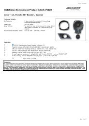
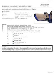
<strong>Installation</strong> <strong>Instructions</strong> <strong>Product</strong>-<strong>Ident</strong>: <strong>47169</strong><br />
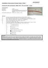
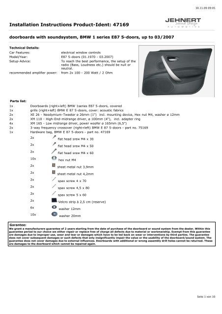
doorboards with soundsystem, BMW 1 series E87 5-doors, up to 03/2007<br />
Technical Details:<br />
Car Features:<br />
electrical window controls<br />
Model/Year: E87 5-doors (01.1970 - 03.2007)<br />
Setup-Advice:<br />
To reach the best performance, the setup of the<br />
radio (Bass, Loudness etc.) should be null or<br />
neutral.<br />
recommended amplifier power: from 2x 100 - 200 Watt / 2 Ohm<br />
Parts list:<br />
1x<br />
Doorboards (right+left) BMW 1series E87 5-doors, covered<br />
1x<br />
grills (right+left) BMW E 87 5-doors, cover: acoustic fabrics<br />
2x<br />
XE 26 - Neodymium-Tweeter ø 26mm (1") incl. mounting device, Hex nut M4, washer ø 12mm<br />
2x<br />
XM 110 - High-End-midrange driver, ø 100mm (4"), incl. adapter ring<br />
4x XM 165 - Low midrange driver, power woofer ø 165mm (6,5")<br />
2x 3-way frequency crossover (right+left) BMW E 87 5-doors - part no. 75169<br />
1x Hardware bag, BMW E 87 5-doors - part no. <strong>47169</strong><br />
2x<br />
2x<br />
2x<br />
10x<br />
2x<br />
2x<br />
2x<br />
2x<br />
2x<br />
2x<br />
6x<br />
10x<br />
flat head srew M4 x 30<br />
flat head srew M4 x 50<br />
flat head srew M4 x 60<br />
hex nut M4<br />
sheet metal nut 3,9mm<br />
sheet metal nut 4,2mm<br />
spax screw 4 x 70<br />
spax screw 4,5 x 80<br />
spax screw 5 x 60<br />
Velcro strip à 2,5 cm (reserve)<br />
washer 12mm<br />
washer 20mm<br />
Garantee:<br />
We grant a manufacturers guarantee of 2 years starting from the date of purchase of the doorboard or sound system from the dealer. Within this<br />
guarantee period to our choice we either repair or replace free of charge all defects due to material or workmanship. Exempt from this guarantee<br />
are damages due to improper use, wear and tear or damages which have to be led back on wear or interventions by third parties. The guarantee<br />
does not cover subsequent damages or such defects that only insignificantly impair the value or the usability of the doorboard/sound system. The<br />
guarantee does not cover damages due to external influences. Doorboards with additional or wrong assembly drill holes cannot be returned. These<br />
are damages to the doorboard which cannot be repaired again.<br />
Seite 1 von 10
30.11.09 09:05<br />
<strong>Installation</strong> <strong>Instructions</strong> <strong>Product</strong>-<strong>Ident</strong>: <strong>47169</strong><br />
1 Disassembly of the door card<br />
1.1 Roll down window completely.<br />
1.2 Carefully pry off the round grill behind the door latch lever and remove the screw underneath(A).<br />
1.3 Pry off the cover grill of the door lock (forward away).<br />
1.4 Pry out the cover of the door handle and remove the 3 screws underneath (B1 + B2) .<br />
1.5 Pry out the module of the window winder and disconnet the switch.<br />
1.6 Lift the door card out of the sealing above and simultaneously move it horizontally and forward away from the inner door metal.<br />
1.7 Remove the Bowden pull wire of the door latch lever.<br />
1.8 Disconnect the original loudspeaker plugs and dismount the original speaker.<br />
Seite 2 von 10
30.11.09 09:05<br />
<strong>Installation</strong> <strong>Instructions</strong> <strong>Product</strong>-<strong>Ident</strong>: <strong>47169</strong><br />
2 Tweeter installation - original mount of the mirror triangle<br />
Remark for the tweeter-installation:<br />
There are two different original mirror triangles - with or without »prepared installation«. With »prepared installation«: Only insert<br />
the tweeter in the given cut-out. Without »prepared installation«: The tweeter has to be adapted in the mirror triangle (cut-out),<br />
alternatively the mirror triangles with a »prepared tweeter installation« are available at your BMW dealer (drivers side: prod.code 51<br />
337 199 597 - co-drivers side: prod.code 51 337 199 598).<br />
2.1 Dismount the mirror triangle. If existing dismount the original tweeter and unplug the cable connection (the original connecting<br />
cables and the tweeter will not be used any more).<br />
2.2 Remove the tweeter out of the catch:<br />
--- > bayonet catch: turn to the right and pull out of the holding device (by means of the screw)<br />
Original mirror triangle without tweeter installation prepared:<br />
2.3 Front side of the mirror triangle with speaker grill (factory installed): position the<br />
mounting plate on the original speaker cut-out - see fig. Mark the outlines of the backside of the<br />
mounting plate »ø 48mm« and carefully go on with a stig saw within the lines marked and cut out<br />
the size of the mounting plate. Possibly adapt the cut-out edge with a dremel.<br />
2.4 Front side of the mirror triangle: install the mounting plate in a way that the JEHNERT signet<br />
is exactly horizontal on the tweeter --> consider the turn of the bajonet catch!<br />
Check: The mounting plate has to end plane on the front side of the mirror triangle.<br />
2.5 Adjust the mounting plate so, that the ring of the catch ends exactly on the front side of the<br />
mirror triangle. Affix all around with hot melt adhesive, silicone of butyl tape on the back side.<br />
2.6 Insert the JEHNERT tweeter in the grooves on the edge of the mounting plate; simultaneously lead the tweeter cable through the<br />
cable entry in the mounting plate. Fasten the tweeter with a slight turn to the left (bajonet catch).<br />
or:<br />
Original mirror triangle with tweeter installation prepared:<br />
Back side of the mirror triangle: install the JEHNERT tweeter in the original mounting place in a<br />
way<br />
that the JEHNERT signet is horizontal on the tweeter. Affix all around with hot melt adhesive.<br />
2.7 Adapt the JEHNERT-tweeter cable with the speaker cable (1,5 - 4 qmm), length of cable up to<br />
where the crossover is installed under the dashboard.<br />
2.8 Reinstall the mirror triangle<br />
with prepared tweeter installation<br />
Seite 3 von 10
30.11.09 09:05<br />
<strong>Installation</strong> <strong>Instructions</strong> <strong>Product</strong>-<strong>Ident</strong>: <strong>47169</strong><br />
3 Handling of door card: doorboard alignment<br />
3.1 Place the door card on a plane surface.<br />
3.2 Dismount the loudspeakers attached to the doorboard for transport protection --> retain the screws for later assembly.<br />
3.3 Place the doorboard without speakers on the door card and align it:<br />
Only precise alignment of the doorboards with the door card warrants optimal fit!<br />
Reference points for alignment:<br />
Reference point 1:<br />
approx. 3-4mm distance between doorboard edge and door handle<br />
Reference line 2:<br />
The lower edge of the doorboard is parallel with the lower edge of the door card - with a distance of approx. 10mm.<br />
Reference point 3:<br />
The stay bolt on the end of the doorboard fits the opening of the original tray.<br />
Seite 4 von 10
30.11.09 09:05<br />
<strong>Installation</strong> <strong>Instructions</strong> <strong>Product</strong>-<strong>Ident</strong>: <strong>47169</strong><br />
4 Handling of door card<br />
4.1 Use the doorboard as template in order to mark fastening points and cut-outs:<br />
Precisely align the doorboard to the fixing points of the door card.<br />
5 Marking fastening points<br />
5.1 Marking of fastening points 1+2 - premounted in the doorboard:<br />
Pressing the panel to the door card makes the screw points visible.<br />
5.2 Marking of the angular fastening point 3:<br />
Put in a piece of packing tape to this position. Measure up the angular position. Mark panel edge and angular position on the tape.<br />
5.3 Marking of the pre-drilled M4-fastening points 4+5:<br />
Use a thin awl to set the marks on the door card.<br />
Example<br />
Seite 5 von 10
30.11.09 09:05<br />
<strong>Installation</strong> <strong>Instructions</strong> <strong>Product</strong>-<strong>Ident</strong>: <strong>47169</strong><br />
6 Handling of door card cut-outs<br />
The cut out behind the speakers are providing the required full volume of the car door:<br />
6.1 Mark the cut outs for the woofers on the door card. Enlarge them approx. 1cm (= approx. outer diameter of the woofers)<br />
IMPORTANT! Check all cut-outs marked:<br />
The fastenings of the doorboard must have to be screwed with the door card.<br />
The fastenings of the door card must not be removed!<br />
6.2 Remove the doorboard again and cut out the positions marked on the door card. Use a compass saw.<br />
Example<br />
6.3 Drill the bore holes for the M4-screws (3, 4 + 5) according to the marks set before - use a 4mm drill and<br />
enlarge to 7-8mm.<br />
Example<br />
Seite 6 von 10
30.11.09 09:05<br />
<strong>Installation</strong> <strong>Instructions</strong> <strong>Product</strong>-<strong>Ident</strong>: <strong>47169</strong><br />
7 Fastening Doorboard<br />
7.1 Screw in the screws supplied with. Affix the doorboard to the door card. Screw all screws only hand-tight .<br />
Secure all screws on the backside of the door card with washers and nuts. (Spax screws with sheet metal nuts as<br />
indicated)<br />
TIP: Treat the screw thread with a liquid for screw-in type fuse. (Speaker vibrations may loosen the screws after<br />
some time)<br />
Example<br />
7.2 Check again for precise fit and tighten the screws.<br />
All cutting edges of the doorboard must fit to the door card snugly all around without gap!<br />
Seite 7 von 10
30.11.09 09:05<br />
<strong>Installation</strong> <strong>Instructions</strong> <strong>Product</strong>-<strong>Ident</strong>: <strong>47169</strong><br />
8 Midrange installation: original mount of the door card<br />
The original speaker in the door card is replaced with the JEHNERT - 100mm High-end-midrange driver:<br />
8.1 Unplug the original speaker. The original speaker fastenings may be used for the installation of the midrange adapter plate<br />
(original cables are not needed any more)<br />
8.2 Connect the JEHNERT midrange with speaker cable (1,5 - 4 qmm). Lead the speaker cable to the mount of the crossover under<br />
the dashboard.<br />
8.3 Insert the midrange with adapter in the original place and use the original screwing.<br />
9 Adaptation amplifier - crossover circuit / Insulation of the car doors<br />
9.1 Carefully remove the moisture protection foil.<br />
9.2 Insulation of the car doors - Important tips against vibration-noise (see attached installation recommendation)<br />
9.3 Adaptation amplifier - crossover circuit:<br />
Lead 1x speaker cable (1,5 - 4 qmm) from amplifier to the crossover circuit under the dashboard.:<br />
mount of crossover circuit: under the dashboard behind the glove box<br />
In order to avoid vibration noise secure all cables with insulating tape e.g.<br />
9.4 Reinstall the moisture protection foil to fit precisely.<br />
9.5 For the bass performance the speakers are using the volume of the car door:<br />
Place the door card on the car door as template and mark the position for the woofers on the<br />
moisture protection foil. Take away the the door card and cut out (u-form see fig.) behind the<br />
woofers. Stabilize the lateral cutting edges in order to avoid vibration noise (e.g. use a adhessing<br />
tape)<br />
Seite 8 von 10
30.11.09 09:05<br />
<strong>Installation</strong> <strong>Instructions</strong> <strong>Product</strong>-<strong>Ident</strong>: <strong>47169</strong><br />
10 <strong>Installation</strong> of crossover circuit + speaker connection<br />
10.1 Precable crossovers - see wiring diagram.<br />
10.2 Install the crossover under the dashboard behind the glove box.<br />
*Important:<br />
Protect the sheet bar against humidity and observe that the sheet bar does not touch any metal parts – danger of short<br />
circuit!<br />
10.3 Connect all speakers to the crossover circuit according to the wiring diagram.<br />
10.4 Insert woofer.<br />
10.5 Notice: You should check the polarity of all woofers after having connected them to the crossover circuit with a 9 volt battery<br />
(input cable on the side of the amplifier):<br />
pole of the crossover circuit input + to + of a 9 Volt battery<br />
pole of the crossover circuit input - to - of a 9 Volt battery<br />
All woofers must move uniformly!<br />
Wrong polarity of a woofer can totally equalize the bass sound!<br />
Seite 9 von 10
30.11.09 09:05<br />
<strong>Installation</strong> <strong>Instructions</strong> <strong>Product</strong>-<strong>Ident</strong>: <strong>47169</strong><br />
11 Insulation of the back side of the door card<br />
In order to avoid vibration noise insulate all cables with insulation tape e.g.<br />
11.1 Insulate the backside of the door card e.g. with self-adhesive vibration suppressing insulation<br />
fleece – see attached installation recommendation.<br />
IMPORTANT:<br />
No insulation material behind loudspeaker, door latch lever and<br />
fastening points of the door card!<br />
Example<br />
12 <strong>Installation</strong> of the door card onto the car doors<br />
12.1 Check up length of the screws and bolts:<br />
In order to prevent damages of mechanic parts of the car doors, please check once again the length of all bolts and screws on the<br />
back side of the door card! No touch with any mechanic parts of the car doors!<br />
(please shorten if necessary)<br />
12.2 Put the door card into the upper sealing of the car door.<br />
12.3 Fit the door card in contrary order of succession.<br />
Final inspection after installation of the door card:<br />
Please check all functions of the operating elements such as seat adjustment, opening of the glove box, window winder<br />
etc.<br />
13 <strong>Installation</strong> of the doorboard grills<br />
13.1 Carefully press grill with Velcro fasteners onto the doorboards:<br />
IMPORTANT: The Velcro fasteners stick very strongly!<br />
Therefore only press the grills to the doorboard at the end of the installation of the doorboard and the soundsystem!<br />
13.2 Further tips see attached installation recommendation.<br />
Seite 10 von 10
Insulation of the door lining<br />
!<br />
Attention / Danger !!!<br />
No insulation behind<br />
the side-airbags (fig. “B”)<br />
☞ Important:<br />
No insulation material behind<br />
- loudspeaker<br />
- door latch lever<br />
- drill ahole for the installation clip (fig. A)<br />
fig.: example of a car door<br />
Important tip:<br />
the use of woofer in the door lining may cause vibrations which lead to annoying rattle noises in the car door<br />
Preventive measurements against vibration noise:<br />
• use our self-adhesive insulation fleece (art.no.: 27000) or a foam material for<br />
the backside of the door lining (see fig. above) or<br />
• stabilize the backside of the door lining by means of a special material<br />
(Glass Fibre Filler or stiffening material)<br />
important: keep the cut-outs for the door-airbags and speakers open<br />
• affix the *backside of the inner door metal with self-adhesive asphalt mats (see fig. * )<br />
• by knocking on the car door, vibrations caused by mechanic parts (e.g. Bowden pull wire etc. )<br />
and wiring harness may be found out. Cover these parts with foamed material, felt or<br />
something like that<br />
• cut off overlapping cable tie (rattle noise)<br />
• adhere felt or foamed material under the original wiring harness<br />
moisture protection foil<br />
front side of<br />
inner door metal<br />
door metal outside<br />
= back side of the<br />
inner door metal<br />
fig.: example of a car door
<strong>Installation</strong> of the speaker’s grill<br />
Precisely align and carefully press grill into the Velcro fasteners.<br />
☞<br />
The Velcro fastener makes a crackling sound when it is closed correctly.<br />
Our Tip:<br />
If the panel cannot be pressed on completely at some points. . .<br />
Cause:<br />
Solution:<br />
the special form at these points and the resulting differences inmaterial cross section of the grill.<br />
the distance can be levelled out with spacers 3 under the Velcro disc.<br />
(Spacers included with the screw kit)<br />
2 self-adhesive Velcro-strip<br />
6. Removing the grills:<br />
1 Velcro fastener<br />
3 Washer M4 ø 20 as spacer<br />
The Velcro fasteners stick together very strongly! The grills can be removed anytime by carefully lifting them off.<br />
Please, avoid any way of forceful yanking at the grills. It could break!<br />
Self-help and fault diagnosis<br />
The following notes serve to help troubleshoot and eliminate faults or malfunctionson your own. If the following<br />
measures are not effective, please call us. Info-Hotline Tel. 0049-7158/95699-0<br />
What can it be if ...<br />
..it doesn’t sound right<br />
...it doesn’t fit correctly<br />
.....grills do not hold<br />
vibrations<br />
possible cause/ solution<br />
· wrong polarity on the subwoofers (see „speaker connection“)<br />
· crosover circuit attached wrong (see „wiring diagram speaker connection“)<br />
· door lining and moisture protection foil not cut out<br />
(see. „installation of teh door lining“ and „installation of the speakers grill“)<br />
· ampilifier doesn’t have enough power (see. „technical details“)<br />
· amplifier connection<br />
· door panel customization (see „handling of the door lining“)<br />
· installation of the panels on the door lining<br />
observe notes (see „installation of the speakers grill“)<br />
observe notes (see „insulation of the door lining“)