part-no. 75110 - Jehnert Sound Design
part-no. 75110 - Jehnert Sound Design
part-no. 75110 - Jehnert Sound Design

Create successful ePaper yourself
Turn your PDF publications into a flip-book with our unique Google optimized e-Paper software.
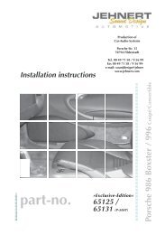
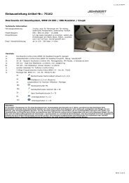
Installation instructions<br />
JEHNERT<br />
<strong>Sound</strong><br />
D E S I G N<br />
Production of<br />
Car-Audio-Systems<br />
<strong>Jehnert</strong><br />
Production<br />
<strong>Sound</strong><br />
of<br />
<strong>Design</strong><br />
development and<br />
Porsche<br />
Car-Audio-Systems<br />
production<br />
Str. 15<br />
of<br />
70794<br />
Car-Audio-Systems<br />
Filderstadt<br />
Porsche Str. 15<br />
Tel. 00 49<br />
70794<br />
71 58<br />
Filderstadt<br />
/ 9 56 99-0<br />
Heinrich-Hertz-Str. 11<br />
Fax 00 49 71 58 / 9 56 99-10<br />
Tel. 00 49 70794 71 58 Filderstadt<br />
e-mail: sounddesign@jehnert.de<br />
/ 9 56 99-0<br />
Fax<br />
www.jehnert.com<br />
00 49 71 58 / 9 56 99-10<br />
e-mail: Tel.: sounddesign@jehnert.de<br />
0049-711-77 97 87- 87<br />
Fax: www.jehnert.com<br />
0049-711-77 78 921<br />
e-mail: sounddesign@jehnert.de<br />
www.jehnert.com<br />
instal.instr.<strong>no</strong>. <strong>75110</strong>FH05/04<br />
<strong>part</strong>-<strong>no</strong>. <strong>75110</strong><br />
VW BUS T4
C o n t e n t s<br />
page<br />
Packing list .......................................................................... 2<br />
1. Disassembly of the door lining .............................................. 3<br />
2. Installation midrange and tweeter in the dashboard ................ 4<br />
3. Panel alignment ................................................................... 5<br />
4. Handling of doorlining / Installation door panel ..................... 6<br />
5. speaker cables / Handling of car doors .................................. 7<br />
6. Insulation of the door lining / car doors ................................. 8<br />
7. Installation of the door lining onto the car doors .................... 9<br />
8. Crossover circuit - Speaker connection .................................. 10<br />
Lodspeaker wiring diagram .................................................. 11<br />
9. Installation of the speaker-grills ............................................ 12<br />
Technical Information .......................................................... 13<br />
Service / fault diag<strong>no</strong>ses ....................................................... 14<br />
Guarantee .......................................................................... 15<br />
Please follow the installation instructions<br />
“step by step”<br />
and check the package contents<br />
Particularly important <strong>no</strong>tes contain the following remarks:<br />
<br />
<strong>75110</strong> VW Bus T 4 - 1 - © JEHNERT SOUND DESIGN
Packing list <strong>75110</strong><br />
Packing unit Check list<br />
door panel, covered (right / left)<br />
Speaker grill, covered (right / left)<br />
tweeter 26 mm<br />
midrange 100 mm Q<br />
Adapter for midrange and tweeter<br />
woofer 165 160 mm (each mounted on the paneel with 4 sheet metal-screws)<br />
crossover (right / left)<br />
standard cables for subwoofer (right / left)<br />
2<br />
2<br />
2<br />
2<br />
2<br />
32<br />
2<br />
2<br />
Hardware bag:<br />
flat flat head head screws screws M4 M x 60 4 x 60<br />
metal screws, 3,9 x 25(for angle fastening)<br />
Spax screws 3,9 x 25 (for angle fastening)<br />
metal screws, 5,0 x 80<br />
Spax screws 5,0 x 80<br />
metal screws, 5,0 x 90<br />
Spax screws 5,0 x 90<br />
sheet metal screws, black 3,9 x 13 (for tweeter mounting)<br />
Spax screws 5,0 x 100<br />
sheet metal nuts ø 3,9 mm<br />
flat round head screw 3,9 x13<br />
Hex nut M4<br />
<br />
sheet<br />
Washer<br />
metal<br />
Ø<br />
screws<br />
20mm<br />
black 3,9 x 10 (for tweeter mounting)<br />
for metric screws 10x + 4x as spacer for Velcro fastener<br />
sheet metal nut Ø 3,9<br />
Velcro strip à 2,5 cm (reserve)<br />
Preassembled hex nut M4 hardware:<br />
washers Velcro Ø fastener 20mm plus strips<br />
velcro flat head strip 2,5 screws cm (Reserve) M 4 x 16<br />
flat head screws M 4 x 50<br />
flat head screws M 4 x 30 (right side)<br />
flat head screws M 4 x 40 (left side)<br />
sheet metal screw, black 3,9 x 13 (for woofer)<br />
sheet metal screw, black 3,5 x 13 (for velcro fastener) 16<br />
The product was carefully packed and checked for its completeness. If you find anything missing, damaged or<br />
defective, please <strong>no</strong>tice our guarantee services on the back of these assembly instructions.<br />
<strong>75110</strong> VW Bus T 4 - 2 - © JEHNERT SOUND DESIGN<br />
44<br />
4<br />
4<br />
8<br />
6<br />
2<br />
2<br />
2<br />
2<br />
4<br />
3<br />
10<br />
2<br />
14<br />
4<br />
4<br />
10<br />
14 16<br />
42<br />
2<br />
1<br />
1<br />
32
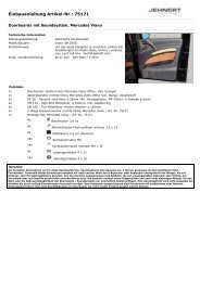
1 . Disassembly of the door lining<br />
A<br />
C<br />
B<br />
1.1. roll down window completely<br />
1.2. pry out the plastic bolt (A) at the door-innerside<br />
and pry out the plastic cap at the door lock (B).<br />
A<br />
B<br />
1.3. pry out the plastic cap at the door handle (C) abhebeln and unscrew the 3<br />
cross head screws underneath.<br />
C 1<br />
C 2<br />
C 3<br />
1.4. Unclip carefully speaker remove grill. the plastic Dismount clips speakers on the door-lining and unsrew edges the and 3 move the<br />
door-lining cross head forward screws underneath..<br />
away from the inner door metal<br />
1.5. Carefully disconnect remove the original the plastic loudspeaker clips on and the remove doorlining the Bowden edges and pull move wire. the doorlining<br />
1.6.<br />
forward<br />
Loosen the<br />
away<br />
screws<br />
from<br />
of<br />
the<br />
the<br />
inner<br />
original<br />
door<br />
tray<br />
metal.<br />
fastening and remove the tray.<br />
1.6. Remove the Bowden pull wire..<br />
1.7. Loosen the screws of the original tray fastening and remove the tray.<br />
<strong>75110</strong> VW Bus T 4 - 3 - © JEHNERT SOUND DESIGN
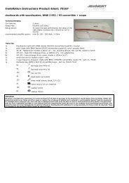
2. midrange and tweeter installation in the dashboard<br />
2.1. tweeter installation on the A-pillar:<br />
2.1.1. Lead the tweeter cable throgh the opening in the mounting bowl and<br />
lengthen it with the speaker cable (1,5 - 4 mm 2 ). Measure the cable<br />
length up to the mount of the crossover under the dashboard (see page 9)<br />
2.1.2. place the tweeter bowl directly above the original speaker grill - parallel<br />
to the front glas:<br />
<br />
for acoustical reasons the tweeter must radiate parallel to the front glass<br />
and has <strong>no</strong>t to be directed to the hearer!<br />
Affix the mounting bowl with a sheet metal screw 3,9x13 10 to the A-pillar.<br />
Insert tweeter and fasten it with a bajonet socket.<br />
IMPORTANT:<br />
Tweeter-position radiate<br />
parallel to the front glas !<br />
2.2. midrange installation in the dashboard:<br />
2.2.1. pry out the speaker grill and remove the original speaker.<br />
2.2.2. connect the JEHNERT-midrange<br />
with a speaker cable (1,5 - 4 mm 2 )<br />
Lead the cable to the mount of the<br />
crossover in the dashboard (page 9)<br />
2.2.3. Insert insert midrange the midrange with with installation<br />
installation ring.<br />
into the original<br />
Fastening<br />
mount so<br />
left<br />
thhat<br />
1x<br />
the fastening cover<br />
with<br />
plates<br />
the<br />
on<br />
screw<br />
the midrange<br />
3,9 x 13<br />
match the<br />
original fastening points. Fasten with<br />
Fastening<br />
original screws.<br />
right 2x<br />
with the screws 3,9 x 13<br />
<strong>75110</strong> VW Bus T 4 - 4 - © JEHNERT SOUND DESIGN
3. Panel alignment<br />
<br />
For doorlinings with ventilation flap:<br />
Some models are equipped with a ventilation flap on the below <strong>part</strong> of the door lining.<br />
It must absolutely be sealed or closed!<br />
3.1. Place the door lining on a plane surface.<br />
3.2. Dismount the loudspeakers attached to the panel for transport protection.<br />
Retain the screws for later assembly.<br />
3.3. Place the panel without loudspeakers on the door lining and align it:<br />
Align the upper edge of the panel directly on the dept under the<br />
door handle.<br />
Reference line<br />
<br />
Only precise alignment of the panel with the door lining<br />
warrants optimal fit.<br />
picture to page 6 - No.5:<br />
fig.: backside of the panel<br />
1<br />
M 4 x 16<br />
already<br />
mounted<br />
fastening points - Panel backside<br />
2<br />
M 4 x 50<br />
already<br />
mounted<br />
3<br />
M 4 x 30<br />
already<br />
mounted<br />
fastening angular for metal screws 3,9 5,0 x 25 30<br />
<strong>75110</strong> VW Bus T 4 - 5- © JEHNERT SOUND DESIGN
4. Handling of door lining / Panel installation - Fastening<br />
4. Handling of door lining / Panel installation - Fastening<br />
1. use the precisely aligned panel as template in order to mark fastening<br />
1. points use the 1- precisely 7: aligned panel as template in order to mark fastening<br />
• points mark 1- the 7: fastening points 1-3_ premounted in the panel:<br />
• pressing mark the the fastening panel to points the door 1-3_ lining premounted leaves visible in the impressions panel: of the screws<br />
pressing Beginning the with panel fastening to the door 1. lining leaves visible impressions of the screws<br />
• marking of fixing points 4-7:<br />
• use marking a thin awl of fixing to set the points marks 4-7: on the door-lining<br />
use TIP to a thin mark awl angular to set fastening the marks points on 6+7: the door-lining<br />
TIP put in to mark a little angular bit of packing fastening tape points to this 6+7: position. Measure up the angular position.<br />
Mark panel edge and angular position on the tape.<br />
put in a little bit of packing tape to this position. Measure up the angular position.<br />
Mark panel edge and angular position on the tape.<br />
2. draw the speakers’ cut-outs onto the door-lining.<br />
2. draw the speakers’ cut-outs onto the door-lining. <br />
3. take away the door build. cut out the speakers’ outlines marked by means<br />
3. of take a compass away the saw door build. cut out the speakers’ outlines marked by means<br />
of a compass saw<br />
4. Drill the holes for the screws<br />
4. Drill according the holes to the for marks the screws set<br />
before. according Use to a the 6mm marks drill. set<br />
(fastening before. Use point a 6mm 1 = drill. 10mm)<br />
(fastening point 1 = 10mm)<br />
<br />
5. place the door panel precise again and do the panel fastening in<br />
5. in place exactly the door follow panel succession: precise again and do the panel fastening in<br />
in<br />
fastening<br />
exactly<br />
from<br />
follow<br />
the<br />
succession:<br />
doorlining - backside<br />
1. fastening fastening from points the doorlining 1-3 secure - backside<br />
1. with fastening washers points and 1-3 nuts secure<br />
with (fig. see washers page 5) and nuts<br />
2. fastening (fig. see page points 5) 6+7<br />
screw 2. fastening the metal-screws<br />
points 6+7<br />
3,9 screw x 25 in into the metal-screws<br />
the angular<br />
fastening 3,9 x 25 into and the secure angular with<br />
sheet fastening metal and nuts secure ø 3,9 with mm.<br />
sheet<br />
fastening<br />
metal<br />
points<br />
nuts ø<br />
4+5<br />
3,9<br />
from<br />
mm.<br />
Spax 3,9 x 25 Spax 3,9 x 25<br />
doorlining fastening points - frontside: 4+5 from<br />
6+7= Spax fastening 3,9 angular x 25 - panel backside Spax - fig 3,9 see page x 255, too<br />
screw doorlining both - frontside: M4x 60 Screws<br />
6+7= fastening angular - panel backside - fig see page 5, too<br />
fastening points 8 - 12<br />
and secure with washers<br />
: <strong>no</strong> pre-drilling<br />
screw in both M4x 60 Screws fastening with metal screws has to be done directly if installing the<br />
nuts<br />
the fastening complete points doorling 8 - 12<br />
and secure with washers<br />
onto : <strong>no</strong> the pre-drilling car door (see page 9)<br />
fastening with metal screws has to be done directly if installing the<br />
and nuts<br />
the complete doorling onto the car door (see page 9)<br />
All cutting edges of the panel must fit to the door lining snugly<br />
all All around cutting without edges of gap the panel must fit to the door lining snugly<br />
<br />
all around without gap<br />
8<br />
8<br />
1 2 3<br />
1 2 3<br />
9 10<br />
9 10<br />
4 5<br />
4 5<br />
M 4 x 60 M 4 x 60<br />
M 4 x 60 M 4 x 60<br />
6= 7=<br />
6= 7=<br />
<strong>75110</strong> VW Bus T 4 - 6 - © JEHNERT SOUND DESIGN<br />
<strong>75110</strong> VW Bus T 4 - 6 - © JEHNERT SOUND DESIGN<br />
11<br />
11<br />
12<br />
12
5. Speaker cables / Preparation of the car doors<br />
5.1. Installation speaker cables<br />
5.1.1. Lead 1 speaker cable (1,5 - 4 mm 2 ) from the amplifier to the crossover<br />
under the dashboord.<br />
5.1.2. Lead 1 speaker cable (1,5 - 4 mm 2 ) from the crossover into the<br />
car door (see wiring diagram page 11)<br />
5.2. IMPORTANT! Preparation of the car doors:<br />
5.2.1. remove the original insulation material (foil) completely!<br />
5.2.2. in order to protect the speakers against humidity close all cut-outs /<br />
depts on the inner door metal with tar mats or similar insulation<br />
material.<br />
5.2.3. to avoic vibration <strong>no</strong>ise tighten all original fastening screws on the<br />
inner door metal.<br />
5.2.4. please observe that the speaker cables are <strong>no</strong>t squeezed by any<br />
mechanic <strong>part</strong>s (window contrrol etc.)<br />
5.2.5. IMPORTANT CONTROL:<br />
hold the door lining with the panel to the car door and check the<br />
following at the 1. speaker cut-out (see fig.):<br />
<br />
<br />
<br />
• the factory installed clipped cable has to be displaced downward<br />
instead of the 1 st woofer in the panel.<br />
• if need be, k<strong>no</strong>ck the door metal internally on this <strong>part</strong> - the<br />
woofer in the panel must <strong>no</strong>t be in contact with the door metal.<br />
IMPORTANT CHECK<br />
(only for the 1st woofer installation)<br />
displace the original<br />
clipped cable downward<br />
and slightly k<strong>no</strong>ck the<br />
door metal internally<br />
IMPORTANT: insulate the car door - see description on page 8<br />
<strong>75110</strong> VW Bus T 4 - 7 - © JEHNERT SOUND DESIGN
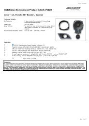
6. insulation of the door lining<br />
!<br />
<br />
attention – danger !!<br />
No insulation behind the<br />
side-airbags (fig. B)<br />
Important:<br />
No insulation material behind<br />
- loudspeaker<br />
- door latch lever<br />
- (fig. A): drill a hole for the<br />
installation clip<br />
<br />
fig.: example backside of the door lining – insulation with our article <strong>no</strong>.: 27000<br />
Important tip:<br />
the use of 4x160mm 165mm mid-woofer /side may cause vibrations which lead to<br />
an<strong>no</strong>ying rattle <strong>no</strong>ises in the car door<br />
some helpful tips:<br />
• use our self-adhesive insulation fleece (art.<strong>no</strong>.: 27000) fora<br />
foam material for<br />
the backside of the door lining (see fig. above) or<br />
• stabilize the backside of the door lining by means of a special material<br />
(Glass Fibre Filler or stiffening material)<br />
Important: keep the cut-outs for the door-airbags and speakers open<br />
• affix the *backside of the inner door metal with self-adhesive asphalt mats (see fig. * )<br />
• by k<strong>no</strong>cking on the car door, vibrations caused by mechanic <strong>part</strong>s (e.g. Bowden pull wire etc. )<br />
and wiring harness may be found out. Cover these <strong>part</strong>s with foamed material, felt or<br />
something like that<br />
• cut off overlapping cable tie (rattle <strong>no</strong>ise)<br />
• adhere felt or foamed material under the original wiring harness<br />
moisture protection foil<br />
front side of<br />
inner door metal<br />
* door metal outside<br />
= back side of the<br />
inner door metal<br />
<strong>75110</strong> VW Bus T 4 - 8 - © JEHNERT SOUND DESIGN
7. installation of the door-lining onto the the car doors<br />
7.1. Check up length of the screws and bolts:<br />
in order to prevent damages of mechanic <strong>part</strong>s of the car doors, please check<br />
once again the length of all bolts and screws on the back side of the door<br />
lining! No touch with any mechanic <strong>part</strong>s of the car doors !<br />
(please shorten if necessary).<br />
7.2. put the door-lining into the upper sealing of the car door<br />
tip: grease the upper door sealing with a residue-free lubricant before<br />
7.3. fit it in contrary order of succession as described on page <strong>no</strong>. 3<br />
7.4. carefully screw in the metal screws 8-12 through the door panel and<br />
the door lining to the door metal.<br />
IMPORTANT: Do <strong>no</strong>t screw in the self cutting metal screws too tight -<br />
it deforms the doormetal and affects the <strong>no</strong>rmal function of<br />
the door mechanic!<br />
fastening point 8-11: 8: Spax metal 5 x 90 screw 5,0 x 80<br />
9-11: 12: Spax metal 5 x 80 screw 5,0 x 90<br />
12: Spax 5 x 100<br />
11<br />
IMPORTANT: Strong tightening of the screws<br />
affects the function of the door mechanic!<br />
10<br />
9<br />
8<br />
12<br />
<br />
Final inspection after panel installation:<br />
• please check all functions of the operating elements such<br />
as seat adjustment, opening of the glove box,<br />
window winder etc.<br />
• <strong>no</strong> insulation directly behind the speaker !<br />
<strong>75110</strong> VW Bus T 4 - 9 - © JEHNERT SOUND DESIGN
8. Crossover circuit - Speaker connection<br />
8.1. precable crossovers - see fig. page 11.<br />
8.2. Recommendation crossover installation: on option under the<br />
dashboard<br />
<br />
IMPORTANT: Do <strong>no</strong>t install the crossover immediately next to<br />
electrical equimpent<br />
8.3. Insert subwoofer and connect all loudspeakers to the crossover circuit with<br />
the included standard cables for subwoofer to the crossover circuit:<br />
parallel wiring see diagram on page 11.<br />
Notice: You should check the the polarity of all of subwoofers all after having<br />
connected before connecting them to them to the to crossover the crossover circuit circuit<br />
with a 9 a volt 9 volt battery<br />
(input with a 9 cable volt battery: on the side of the amplifier).<br />
<br />
pole of the crossover circuit input to of a 9 Volt battery<br />
pole of the crossover circuit input to of a 9 Volt battery<br />
All subwoofers must move uniformly!<br />
Wrong polarity of a subwoofer can totally<br />
equalize the bass sound!<br />
<strong>75110</strong> VW Bus T 4 - 10 - © JEHNERT SOUND DESIGN
i g h<br />
a n c<br />
a n c<br />
a n c<br />
r<br />
r<br />
r<br />
r<br />
H<br />
e<br />
i g h<br />
n c<br />
a<br />
e<br />
P<br />
e<br />
r<br />
c<br />
a n<br />
e<br />
r<br />
Loudspeaker wiring diagram<br />
Connect all loudspeakers and crossover circuits:<br />
Circuit diagram of 2-way crossover / 4x subwoofer<br />
recommended power<br />
from 200 Watt RMS / 4 Ohm<br />
amplifier<br />
JEHNERT<br />
<strong>Sound</strong><br />
D E S I G N<br />
VW BUS T 4<br />
3-way crossover circuit<br />
woofer<br />
INPUT<br />
tweeter<br />
midrange<br />
S p e a k e r<br />
M A D E I N G E R M A N Y<br />
T w e e t e r<br />
<strong>Sound</strong><br />
JEHNERT<br />
<strong>Sound</strong><br />
D E S I G N<br />
r m<br />
f o<br />
H<br />
h<br />
g i<br />
S p e a k e r<br />
M A D E I N G E R M A N Y<br />
M i d r a n g e<br />
JEHNERT<br />
<strong>Sound</strong><br />
D E S I G N<br />
P<br />
r m<br />
f o<br />
H<br />
S p e a k e r<br />
M A D E I N G E R M A N Y<br />
W O O F E R<br />
JEHNERT<br />
<strong>Sound</strong><br />
D E S I G N<br />
P<br />
e<br />
r m<br />
f o<br />
e<br />
H<br />
i g h<br />
S p e a k e r<br />
M A D E I N G E R M A N Y<br />
W O O F E R<br />
JEHNERT<br />
<strong>Sound</strong><br />
D E S I G N<br />
P<br />
e<br />
r m<br />
f o<br />
e<br />
D E S I G N<br />
D E S I G N<br />
H<br />
W O O F E R<br />
JEHNERT<br />
<strong>Sound</strong><br />
H<br />
W O O F E R<br />
JEHNERT<br />
<strong>Sound</strong><br />
e<br />
i g h<br />
S p e a k e r<br />
M A D E I N G E R M A N Y<br />
a n c<br />
i g h<br />
S p e a k e r<br />
M A D E I N G E R M A N Y<br />
= set of cables supplied with<br />
P<br />
P<br />
e<br />
r m<br />
e<br />
r m<br />
f o<br />
f o<br />
e<br />
<strong>75110</strong> VW Bus T 4 - 11 - © JEHNERT SOUND DESIGN
9. Installation of the speaker’s grill:<br />
9.1. Precisely align and carefully press grill into the Velcro fasteners.<br />
<br />
The Velcro fastener makes a crackling sound<br />
when it is closed correctly.<br />
9.2. Our Tip:<br />
If the panel can<strong>no</strong>t be pressed on completely at some points. . .<br />
Cause:<br />
Solution:<br />
the special form at these points and the resulting differences in<br />
material cross section of the grill.<br />
the distance can be levelled out with spacers 3 under the<br />
Velcro disc.<br />
(Spacers included with the screw kit)<br />
grill<br />
2 self-adhesive Velcro-strip<br />
1 Velcro fastener<br />
3 Washer M4 ø 20 as spacer<br />
doorpanel<br />
9.3.<br />
Removing the grills:<br />
The Velcro fasteners stick together very strongly!<br />
The grills can be removed anytime by carefully lifting them off.<br />
Please, avoid any way of forceful yanking at the grills.<br />
It could break!<br />
<strong>75110</strong> VW Bus T 4 - 12 - © JEHNERT SOUND DESIGN
T e c h n i c a l i n f o r m a t i o n<br />
Equipment:<br />
electric window control<br />
Model/ year: T 4<br />
Insulation: is absolutely necessary ! - see page 8<br />
Note about setting:<br />
To obtain optimal stereoscopic sound, all settings<br />
on the radio (bass, treble, loudness etc) should be<br />
set to zero or neutral.<br />
Recommended<br />
amplifier power :<br />
Metal cutwork :<br />
from 2x 200 - 360 Watt RMS / 4 Ohm<br />
<strong>no</strong>t necessary<br />
Cut-outs for loudspeaker/ 4 x 144mm (max.outer dimensions subwoofer 165 mm)<br />
each side (max.installation depth subwoofer 65 mm)<br />
DIN-Euro-Norm-standard basket ø 6“ made it fit<br />
<strong>Sound</strong>-System:<br />
3-ways<br />
4 x 165mm 160 subwoofer/ side<br />
1 x 100 mm midrange / side<br />
1 x 26 mm tweeter / side<br />
car-customized crossover network<br />
max.continuous Watt/RMS:<br />
car specific frequency range:<br />
Total impedance:<br />
2 x 300/500Watt<br />
39-22.000 Hz<br />
4 Ohm<br />
We reserve the right to make technical changes, as well as development.<br />
<strong>75110</strong> VW Bus T 4 - 13 - © JEHNERT SOUND DESIGN
Technical questions: Hotline: 0049-711-77 58 97 / 9 87-87 56 99-0<br />
Technical questions: Hotline: 0049-711-77 5897 / 987-87<br />
56 99-0<br />
It is our pleasure to help you!<br />
It is our pleasure to help you!<br />
Self-help and fault diag<strong>no</strong>sis<br />
Self-help and fault diag<strong>no</strong>sis<br />
The following <strong>no</strong>tes serve to help troubleshoot and eliminate faults or malfunctions<br />
on The your following own. If <strong>no</strong>tes the following serve to help measures troubleshoot are <strong>no</strong>t and effective, eliminate please faults call or us. malfunctions<br />
What on your can own. it If be the if following ... measures possible are cause/ <strong>no</strong>t effective, solution please call us.<br />
What ..it doesn’t can it sound be if right. ... possible wrong polarity cause/ on solution the subwoofers ( page 10)<br />
..it doesn’t sound right. crosover wrong polarity circuit on attached the subwoofers wrong ( ( page page 11) 10)<br />
Mirko Schwarz Doorlining crosover circuit<br />
Steffen Kretzschmar and moisture attached protection wrong ( Marc page foil<br />
Sitter 11)<br />
<strong>no</strong>t cut out ( page 6+9)<br />
Mirko Development Schwarz Doorlining Steffen Saddlery Kretzschmar<br />
/ Completion and moisture protection Export Marc foil<br />
/ Sitter<br />
Service<br />
amplifier <strong>no</strong>t cut out doesn’t ( page have 6+9)<br />
Development<br />
Saddlery / Completion e<strong>no</strong>ugh power Export /( Service page 13)<br />
amplifier doesn’t connection have e<strong>no</strong>ugh power ( page 13)<br />
Dear customer,<br />
amplifier connection<br />
...it doesn’t fit correctly. door panel customization ( page 5)<br />
We Dear have customer, taken great care to explain the procedures in our installation instructions<br />
...it doesn’t fit correctly. door<br />
more detailed and “step by step”. installation panel customization of the panels on ( the page door 5) lining (page 6)<br />
We have taken great care to explain the procedures in our installation instructions<br />
.....grills<br />
more Your tips detailed<br />
do and <strong>no</strong>t suggestions and<br />
hold.<br />
“step by help step”. installation of the panels on the door lining (page 6)<br />
observe us for the <strong>no</strong>tes future on to eliminate page 12! uncertainties and<br />
misinterpretation. Your tips and suggestions Therefore, help please us for inform the future us. what to eliminate you would uncertainties like to be and improved<br />
.....grills do <strong>no</strong>t hold. observe <strong>no</strong>tes on page 12!<br />
vibrations or misinterpretation. what we should Therefore, still change. please insulation, inform see us. <strong>no</strong>tes what on you page would like 8 to be improved<br />
vibrations or what we should still change. insulation, see <strong>no</strong>tes on page 8<br />
We thank you for your support!<br />
We thank you for your support!<br />
Self-help and fault diag<strong>no</strong>sis<br />
Self-help and fault diag<strong>no</strong>sis<br />
The following <strong>no</strong>tes serve to help troubleshoot and eliminate faults or malfunctions<br />
on The your following own. If <strong>no</strong>tes the following serve to help measures troubleshoot are <strong>no</strong>t and effective, eliminate please faults call or us. malfunctions<br />
What on your can own. it If be the if following ... measures possible are cause/ <strong>no</strong>t effective, solution please call us.<br />
What ..it doesn’t can it sound be if right. ... possible wrong polarity cause/ on solution the subwoofers ( page 10)<br />
..it doesn’t sound right. crosover wrong polarity circuit on attached the subwoofers wrong ( ( page page 11) 10)<br />
Doorlining crosover circuit and moisture attached protection wrong ( page foil 11)<br />
<strong>no</strong>t Doorlining cut out and ( page moisture 6+9) protection foil<br />
amplifier <strong>no</strong>t cut out doesn’t ( page have 6+9) e<strong>no</strong>ugh power ( page 13)<br />
amplifier doesn’t connection have e<strong>no</strong>ugh power ( page 13)<br />
...it doesn’t fit correctly.<br />
amplifier connection<br />
door panel customization ( page 5)<br />
...it doesn’t fit correctly. door installation panel customization of the panels on ( the page door 5) lining (page 6)<br />
.....grills do <strong>no</strong>t hold.<br />
installation of the panels on the door lining (page 6)<br />
observe <strong>no</strong>tes on page 12!<br />
.....grills do <strong>no</strong>t hold.<br />
vibrations<br />
observe <strong>no</strong>tes on page 12!<br />
insulation, see <strong>no</strong>tes on page 8<br />
vibrations insulation, see <strong>no</strong>tes on page 8<br />
<strong>75110</strong> VW Bus T 4 - 14 - © JEHNERT SOUND DESIGN<br />
<strong>75110</strong> VW Bus T 4 - 14 - © JEHNERT SOUND DESIGN
G u a r a n t e e<br />
We grant a manufacturers guarantee of 2 years starting from the date of purchase<br />
of the door panels or sound system from the dealer.<br />
Within this guarantee period to our choice we either repair or replace free of<br />
charge all defects due to material or workmanship.<br />
Exempt from this guarantee are damages due to improper use, wear and tear or<br />
damages which have to be led back on wear or interventions by third <strong>part</strong>ies.<br />
The guarantee does <strong>no</strong>t cover subsequent damages or such defects that only<br />
insignificantly impair the value or the usability of the panels/sound system.<br />
The guarantee does <strong>no</strong>t cover damages due to external influences.<br />
<br />
Panels with additional or wrong assembly drill holes can<strong>no</strong>t be returned.<br />
These are damages to the panel which can<strong>no</strong>t be repaired again.<br />
2004/by.aj/FH - 15 -