NOS 05040 Nitrous System Installation Instructions - Jegs
NOS 05040 Nitrous System Installation Instructions - Jegs
NOS 05040 Nitrous System Installation Instructions - Jegs
Create successful ePaper yourself
Turn your PDF publications into a flip-book with our unique Google optimized e-Paper software.
P/N A5072-S<strong>NOS</strong><br />
INLINE SPORTSMAN FOGGER SYSTEM<br />
Kit Numbers: 05030<strong>NOS</strong>, 05030-FI<strong>NOS</strong>, <strong>05040</strong><strong>NOS</strong>, and <strong>05040</strong>-FI<strong>NOS</strong><br />
OWNER’S MANUAL<br />
NOTICE: <strong>Installation</strong> of <strong>Nitrous</strong> Oxide <strong>System</strong>s Inc. products signifies that you have read this document and have<br />
agreed to the terms stated within.<br />
It is the purchaser’s responsibility to follow all installation instruction guidelines and safety procedures supplied with the product<br />
as it is received by the purchaser to determine the compatibility of the product with the vehicle or the device the purchaser<br />
intends to install the product on.<br />
<strong>Nitrous</strong> Oxide <strong>System</strong>s Inc. assumes no responsibility for damages occurring from accident, misuse, abuse, improper<br />
installation, improper operation, lack of reasonable care, or all previously stated reasons resulting from incompatibility with other<br />
manufacturers’ products.<br />
<strong>Nitrous</strong> Oxide <strong>System</strong>s Inc. assumes no responsibility or liability for damages incurred by the use of products manufactured or<br />
sold by <strong>Nitrous</strong> Oxide <strong>System</strong>s Inc. on vehicles used for competition or racing.<br />
<strong>Nitrous</strong> Oxide <strong>System</strong>s Inc. neither recommends nor condones the use of products manufactured or sold by <strong>Nitrous</strong> Oxide<br />
<strong>System</strong>s Inc. on vehicles, which may be driven on public roads or highways, and assumes no responsibility for damages<br />
incurred by such use.<br />
<strong>NOS</strong> nitrous oxide is legal for use in most states when used in accordance with state and local traffic laws. <strong>NOS</strong> does not<br />
recommend or condone the use of its products in illegal racing activities.
<strong>NOS</strong> has not pursued California Air Research Board (CARB) exemptions for these kits, hence, they are not legal for use on<br />
pollution-controlled vehicles in California. A correctly installed <strong>NOS</strong> nitrous system should not alter the emission control<br />
performance of your vehicle under standard EPA test cycle conditions.<br />
NOTICE: The <strong>NOS</strong> Sportsman Fogger Kit is not intended for use on hatchback type vehicles without the use of <strong>NOS</strong><br />
P/N 16160<strong>NOS</strong> (External Aluminum Blow-Down Tube) and 16166<strong>NOS</strong> (Racer Safety Pressure Relief Cap).<br />
HAZARDS DEFINED<br />
This manual presents step-by-step instructions that describe the process of installing your <strong>NOS</strong> <strong>Nitrous</strong> Oxide Injection <strong>System</strong>.<br />
These procedures provide a framework for installation and operation of this kit. Parts are referenced by name and number to<br />
avoid confusion. Within the instructions, you are advised of potential hazards, pitfalls, and problems to avoid. The following<br />
examples explain the various hazard levels:<br />
WARNING! Failure to comply with instructions may result in injury or death.<br />
CAUTION! Failure to comply with instructions may result in damage to equipment.<br />
NOTE: This information is important, needs to be emphasized, and is set apart from the rest of the text.<br />
HINT: These special instructions provide a handy work tip.<br />
NITROUS OXIDE INJECTION SYSTEM SAFETY TIPS<br />
WARNINGS<br />
Do not attempt to start the engine if the nitrous has been injected while the engine was not running. Disconnect the<br />
coil wire and turn the engine over with the throttle wide open for several revolutions before attempting to start. Failure<br />
to do so can result in extreme engine damage.<br />
Never permit oil, grease, or any other readily combustible substances to come in contact with cylinders, valves,<br />
solenoids, hoses, and fittings. Oil and certain gases (such as oxygen and nitrous oxide) may combine to produce a<br />
highly flammable condition.<br />
Never interchange nitrous and fuel solenoids. Failure to follow these simple instructions can result in extreme engine<br />
damage and/or personal injury.<br />
Never drop or violently strike the bottle. Doing so may result in an explosive bottle failure.<br />
Never change pressure settings of safety relief valve on the nitrous bottle valve. Increasing the safety relief valve<br />
pressure settings may create an explosive bottle hazard.<br />
Identify the gas content by the <strong>NOS</strong> label on the bottle before using. If the bottle is not identified to show the gas<br />
contained, return the bottle to the supplier.<br />
Do not deface or remove any markings, which are on the nitrous bottle.<br />
<strong>Nitrous</strong> bottle valves should always be closed when the system is not being used.<br />
Notify the supplier of any condition, which might have permitted any foreign matter to enter the valve or bottle.<br />
Keep the valves closed on all empty bottles to prevent accidental contamination.<br />
After storage, open the nitrous bottle valve for an instant to clear the opening of any possible dust or dirt.<br />
It is important that all threads on the valves and solenoids are properly mated. Never force connections that do not fit<br />
properly.<br />
CONGRATULATIONS on purchasing your <strong>NOS</strong> <strong>Nitrous</strong> Oxide Injection <strong>System</strong>. Your system is composed of the highest<br />
quality components available. It should provide many miles of trouble-free performance when used correctly. If you have any<br />
questions regarding the performance of your system, call <strong>NOS</strong> Technical Service at 1-866-GOHOLLEY.<br />
2
TABLE OF CONTENTS<br />
What is <strong>Nitrous</strong> Oxide?……………………………………………………………………………………... 4<br />
Do’s and Don’ts of <strong>Nitrous</strong> Oxide………………………………………………………………………….4<br />
Chapter 1 Introduction to Your <strong>NOS</strong> <strong>Nitrous</strong> Oxide Kit……………………………………………….4<br />
1.1 General Information…………………………………………………………………………. 4<br />
1.2 Sportsman Fogger <strong>System</strong> Requirements…………………..………………………….. 5<br />
1.3 Kit Components……………………………………………………………………………… 6<br />
Chapter 2 Kit <strong>Installation</strong>…………………………………………………………………………………...10<br />
2.1 Bottle Mounting <strong>Instructions</strong>………………………………………………………………. 10<br />
2.2 Bottle Orientation……………………………………………………………………………..10<br />
2.3 Bottle <strong>Installation</strong>……………………………………………………………………………..10<br />
2.4 Fogger Nozzle <strong>Installation</strong>.……………..………………………………………………….. 12<br />
2.5 Fogger Nozzle Feed Tube Mounting……………………………………………………… 12<br />
2.5.1 <strong>Nitrous</strong> Feed Tube <strong>Installation</strong>……………………………………………….. 12<br />
2.5.2 Fuel Feed Tube <strong>Installation</strong>…………………………………………………… 14<br />
2.6 <strong>Nitrous</strong> and Fuel Solenoid Mounting……………………………………………..……… 16<br />
2.6.1 <strong>Nitrous</strong> Solenoid <strong>Installation</strong>…………………………………………………..16<br />
2.6.2 Fuel Solenoid <strong>Installation</strong>………………………………………………………16<br />
2.7 Main <strong>Nitrous</strong> Feed Line Mounting………..…………………………………………..…… 17<br />
2.8 Fuel Supply Connection………………………….………..……………………………….. 17<br />
2.8.1 Fuel Solenoid Feed Line Inst.—Kits 05030<strong>NOS</strong> & <strong>05040</strong><strong>NOS</strong>.………….. 17<br />
2.8.2 Fuel Solenoid Feed Line Inst.—Kits 05030-FI<strong>NOS</strong> & <strong>05040</strong>-FI<strong>NOS</strong>...….. 17<br />
2.8.3 Fuel <strong>System</strong>s with Fuel Logs…………………….…………………………… 17<br />
2.8.4 Fuel <strong>System</strong>s without Fuel Logs…………….………………………………. 18<br />
2.9 Electrical <strong>System</strong> ……………..…………………………………………………………….. 19<br />
2.9.1 Electrical <strong>System</strong> Inst.—Kits 05030<strong>NOS</strong> & <strong>05040</strong><strong>NOS</strong>…………………… 19<br />
2.9.2 Electrical <strong>System</strong> Inst.—Kits 05030-FI<strong>NOS</strong> & <strong>05040</strong>-FI<strong>NOS</strong>…………….. 21<br />
Chapter 3 Baseline Tuning Suggestions.……………………………………………………………….. 22<br />
Chapter 4 Preparing for Operation………………………………………………………………………. 22<br />
Chapter 5 Advanced Tuning for Maximum Power……………………………………………………. 23<br />
5.1 Optimum <strong>Nitrous</strong>/Fuel Jetting…………………………………………………………….. 23<br />
5.1.1 Determining Optimum <strong>Nitrous</strong>/Fuel Jetting……………………………….. 23<br />
5.1.2 Determining Optimum Ignition Timing……………………………………… 24<br />
Chapter 6 Routine Maintenance………………………………………………………………………….. 24<br />
6.1 <strong>Nitrous</strong> Solenoid Filter……………………………………………………………………… 24<br />
6.2 <strong>Nitrous</strong> Solenoid Plunger…………………………………………………………………... 25<br />
6.2.1 General Information…………………………………………………………….. 25<br />
6.2.2 <strong>Nitrous</strong> Solenoid Plunger Disassembly & Inspection……………………. 25<br />
Appendix A Troubleshooting Guide…………………………………………………………………….. 26<br />
<strong>Nitrous</strong> Oxide Accessories………………………………………………………………………………… 28<br />
LIST OF FIGURES AND TABLES<br />
Figure 1 Kits 05030<strong>NOS</strong> & <strong>05040</strong><strong>NOS</strong> Components………..…………….………………………….. 7<br />
Figure 2 Kits 05030-FI<strong>NOS</strong> & <strong>05040</strong>-FI<strong>NOS</strong> <strong>System</strong> Component……………………………...…... 9<br />
Figure 3 <strong>Nitrous</strong> Bottle Siphon Tube Orientation…………………………………………………….. 10<br />
Figure 4 <strong>Nitrous</strong> Bottle Mounting Orientation…………………….…………………………………... 10<br />
Figure 5 <strong>System</strong> Exploded View………….………………………………………………….…………... 11<br />
Figure 6 Fogger Nozzle Mounting Position.…………..……………………………………………….. 12<br />
Figure 7 End Fogger Nozzle Feed Tube………………………………………………………………… 14<br />
Figure 8 Solenoid Extension Tube <strong>Installation</strong>…………………………………………………………15<br />
Figure 9 End Fogger Nozzle Feed Tube………………………………………………………………… 15<br />
Figure 10/11 Typical Fuel Logs…………………………………………………………………………… 18<br />
Figure 12 Fuel Filter/Banjo Fitting……………………………………………………………………….. 19<br />
Figure 13 Schematic of “Drilled Out” Banjo Fitting………………………………………………….. 19<br />
Figure 14 Throttle Microswitch <strong>Installation</strong>……………………………………………………………. 20<br />
Figure 15 Wiring Diagram—Vehicles without Fuel Injection………………………………………. 20<br />
Figure 16 Throttle Microswitch <strong>Installation</strong>……………………………………………………………. 21<br />
Figure 17 Wiring Diagram—Vehicles with Fuel Injection……………………………………………. 22<br />
Figure 18 Spark Plug Condition………………………………………………………………………….. 23<br />
Figure 19 Exploded View of Typical Solenoid…………………………………………………………. 26<br />
Table 1 Jetting and Power Levels………………………………………………………………………... 5<br />
Table 2 Kits 05030<strong>NOS</strong> & <strong>05040</strong><strong>NOS</strong> Parts List……………………………………………………….. 6<br />
Table 3 Kits 05030-FI<strong>NOS</strong> & <strong>05040</strong>-FI<strong>NOS</strong> Parts List……………………………..………………….. 8<br />
Table 4 Suggested Baseline Tuning Combinations…..……………………………………………….22<br />
3
WHAT IS NITROUS OXIDE?<br />
NITROUS OXIDE…<br />
…Is a cryogenic gas composed of nitrogen and oxygen molecules<br />
…Is 36% oxygen by weight<br />
…Is non-flammable by itself<br />
…Is stored as a compressed liquid<br />
…Exists in two grades—U.S.P. and <strong>Nitrous</strong> Plus:<br />
U.S.P. is medical grade nitrous oxide; its common use is dental and veterinary anesthesia. It is also commonly used as a<br />
propellant in canned whipped cream. U.S.P. is not available to the public.<br />
<strong>Nitrous</strong> Plus differs from U.S.P. in that it contains trace amounts of sulphur dioxide added to prevent substance abuse.<br />
<strong>Nitrous</strong> Plus is intended for automotive applications and is available for sale to the public<br />
In automotive applications, <strong>Nitrous</strong> Plus and fuel are injected into the engine’s intake manifold, which produces the following<br />
results:<br />
Lowers engine intake air temperature, producing a dense inlet charge.<br />
Increases the oxygen content of the inlet charge (air is only 22 percent oxygen by weight).<br />
Increases the rate at which combustion occurs in the engine’s cylinders.<br />
Do’s and Don’ts of <strong>Nitrous</strong> Oxide<br />
Do’s<br />
Read all instructions before attempting to install your <strong>NOS</strong> nitrous system.<br />
Make sure your fuel delivery system is adequate for the nitrous jetting you have chosen. Inadequate fuel pressure or flow<br />
will result in engine damage.<br />
Use 14 gauge (minimum) wire when installing electrical system components.<br />
Use high-quality connections at all electrical joints.<br />
Use Teflon-based paste on pipe style fittings.<br />
Make sure your engine and related components (ignition, carburetor, and driveline) are in proper working condition.<br />
If nitrous is accidentally injected into the engine when it is not running, remove the engine coil wire, open the<br />
throttle, and crank the engine 10 to 15 seconds before starting. Failure to do so can result in an explosive engine<br />
failure.<br />
Use your <strong>NOS</strong> nitrous system only at wide-open throttle and at engine speeds above 3000 RPM.<br />
Install a proper engine to chassis ground. Failure to do so may result in an explosive failure of the main nitrous<br />
supply line.<br />
Use a high-quality fuel, as suggested in Chapter 3, Baseline Tuning Suggestions.<br />
Don’ts<br />
Engage your nitrous system with the engine off. Severe engine damage can occur.<br />
Modify <strong>NOS</strong> nitrous systems (if you need a non-stock item, call <strong>NOS</strong> Technical Service for assistance)<br />
Overtighten AN type fittings.<br />
Use Teflon Tape on any pipe threads. Pieces of Teflon tape can break loose and become lodged in nitrous or fuel<br />
solenoids or solenoid filters. Debris lodged in a nitrous or fuel solenoid can cause catastrophic engine failure.<br />
<br />
<br />
<br />
<br />
<br />
Use sealant of any kind on AN type fittings.<br />
Allow nitrous pressure to exceed 1100 psi. Excessive pressure can cause swelling or in extreme cases failure of the nitrous<br />
solenoid plunger. Solenoid plungers are designed so that pressure-induced failures will prevent the valve from operating.<br />
No leakage should occur with this type of failure.<br />
Inhale nitrous oxide. Death due to suffocation can occur.<br />
Allow nitrous oxide to come in contact with skin. Severe frostbite can occur.<br />
Use octane boosters that contain methanol. Fuel solenoid failure may occur, producing severe engine damage.<br />
Chapter 1 Introduction to your <strong>NOS</strong> <strong>Nitrous</strong> Oxide Kit<br />
1.1 General Information<br />
Direct port injection style kits are intended to provide maximum performance and tunability in a nitrous oxide injection system.<br />
Horsepower increases from these kits will vary with engine displacement and configuration. However, approximate power<br />
increases can be estimated based upon the massflow of nitrous oxide into the engine. On a typical engine, the following power<br />
increases approximate what you can expect to see.<br />
4
Table 1 Jetting and Power Levels<br />
Configuration <strong>Nitrous</strong>/Fuel<br />
Jetting<br />
05030<strong>NOS</strong> 18-18<br />
20-20<br />
05030-FI<strong>NOS</strong> 20-14<br />
22-16<br />
<strong>05040</strong><strong>NOS</strong> 18-18<br />
20-20<br />
<strong>05040</strong>-FI<strong>NOS</strong> 20-14<br />
22-16<br />
Approximate Power<br />
Increase (BHP)<br />
45<br />
70<br />
70<br />
85<br />
65<br />
110<br />
110<br />
125<br />
Approximate N 2 O<br />
Consumption Rate<br />
.55lbs./10 sec.<br />
.70lbs./10 sec.<br />
.70lbs./10 sec.<br />
.85lbs./10 sec.<br />
.85lbs./10 sec.<br />
1.10lbs./10 sec.<br />
1.10lbs./10 sec.<br />
1.35lbs./10 sec.<br />
NOTE: A full #10 bottle will weigh 25 lbs. For best performance, the bottle should be refilled when it weighs 17 to 18 lbs.<br />
1.2 Sportsman Fogger <strong>System</strong> Requirements<br />
When used correctly, <strong>NOS</strong> nitrous oxide injection elevates cylinder pressures and temperatures while increasing the combustion<br />
rate. These characteristics make the engine more sensitive to detonation. To ensure proper performance and engine life<br />
with all Sportsman Fogger kits, the following is an absolute must:<br />
Adequate Fuel Pressure and Delivery<br />
When designing your fuel system, plan on your fuel pump(s) and lines flow at least 0.10 gallons of gasoline per hour per<br />
horsepower at the fuel pressure your engine is designed to operate at. For Kit Numbers 05030<strong>NOS</strong> and <strong>05040</strong><strong>NOS</strong>, typical fuel<br />
pressures are between 5 and 7 psig. Kit Numbers 05030-FI<strong>NOS</strong> and <strong>05040</strong>-FI<strong>NOS</strong> are applicable to vehicles that operate at<br />
35-45 psig at wide-open throttle.<br />
NOTE: If you intend to increase engine output by more than 40-50%, the following modifications in engine<br />
configuration are suggested.<br />
Forged Pistons<br />
Cast pistons are very prone to failure at elevated cylinder temperatures and pressures.<br />
Connecting Rods<br />
Cast connecting rods tend to break under the high compressive loads generated with large doses of nitrous oxide. For most<br />
applications, factory forged connecting rods are acceptable. For very high output applications, a steel billet or aluminum rod is<br />
suggested.<br />
Cylinder Block<br />
Four-bolt main cap blocks reduce the tendency for the main caps to “walk” under high-output loading. Cylinder head studs<br />
decrease the chance of cylinder heads lifting or moving relative to the cylinder block deck surface.<br />
Crankshaft<br />
Stock-type cast crankshafts may break. For most applications, a factory forging is acceptable. Aftermarket units are<br />
recommended for very high output applications.<br />
High Output Ignition <strong>System</strong><br />
Stock ignition systems are prone to producing misfires at high-RPM, when subjected to high cylinder pressures. A quality<br />
aftermarket-racing ignition is suggested.<br />
5
1.3 Kit Components<br />
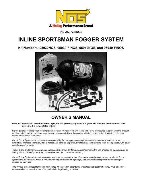
Before beginning the installation of your <strong>NOS</strong> kit, compare the components in your kit with those shown in Figure 1 or 2, and<br />
listed in Table 2 or 3. If any components are missing, please contact <strong>NOS</strong> Technical Support at 1-866-GOHOLLEY.<br />
Table 2 Kit Numbers 05030<strong>NOS</strong> and <strong>05040</strong><strong>NOS</strong> Parts List<br />
Item Description Quantity <strong>NOS</strong> P/N<br />
(1) Bottle Valve Adapter 1 16220<strong>NOS</strong><br />
(2) Bottle Washer 1 16210<strong>NOS</strong><br />
(3) Bottle Bracket Set 1 14125<strong>NOS</strong><br />
(4) Bottle 10 lb. 1 14745<strong>NOS</strong><br />
(5) 1/16” NPT Tap 1 15990<strong>NOS</strong><br />
(6) Fogger Nozzle * 13700B<strong>NOS</strong><br />
(7) Funnel Jet * *<br />
(8) Solenoid Extension Tube * 16300-S<strong>NOS</strong><br />
(9) 3AN x 1/8” B-Nut (Blue) * 17540<strong>NOS</strong><br />
(10) 1/8” Ferrule * 16404<strong>NOS</strong><br />
(11) 1/16” NPT Compression Fitting * 16430<strong>NOS</strong><br />
(12) 1/8” NPT x 1/16” NPT Distribution Block 2 *<br />
(13) 3AN x 1/8” B-Nut (Red) * 17541<strong>NOS</strong><br />
Not shown 12” 4 AN x 3 AN Hose (Blue) 1 15340<strong>NOS</strong><br />
(14) Power Shot N 2 O Solenoid 1 16020<strong>NOS</strong><br />
(15) N 2 O Filter 1 15570<strong>NOS</strong><br />
(16) Power Shot Fuel Solenoid 1 16080<strong>NOS</strong><br />
(17) Fuel Filter 1 15540<strong>NOS</strong><br />
(18) 4AN x 14 ft. N 2 O Hose (Blue) 1 15295<strong>NOS</strong><br />
(19) Rubber Fuel Hose (2 ft.) 1 15000-S<strong>NOS</strong><br />
(20) Hose Clamp 4 -------<br />
(21) Microswitch and Bracket 1 15640<strong>NOS</strong><br />
(22) Arming Switch 1 15602<strong>NOS</strong><br />
(23) 1/8” NPT x 3AN 90° Fitting (Blue) 1 17650<strong>NOS</strong><br />
(24) 1/8” NPT x 3AN 90° Fitting (Red) 1 17651<strong>NOS</strong><br />
(25) 3AN Hose (2 ft. Blue) 1 15060-1<strong>NOS</strong><br />
(26) Solenoid Mounting Bracket with screws 1 16505-S<strong>NOS</strong><br />
(27) 3AN Hose (2 ft. Red) 1 15060-2<strong>NOS</strong><br />
(28) Fuel TEE 5/16” 1 15534<strong>NOS</strong><br />
*Varies with application.<br />
6
Figure 1 Kits 05030<strong>NOS</strong> & <strong>05040</strong><strong>NOS</strong> Components<br />
7
Table 3 Kit Numbers 05030-FI<strong>NOS</strong> and <strong>05040</strong>-FI<strong>NOS</strong> Parts List<br />
Item Description Quantity <strong>NOS</strong> P/N<br />
(1) Bottle Valve Adapter 1 16220<strong>NOS</strong><br />
(2) Bottle Washer 1 16210<strong>NOS</strong><br />
(3) Bottle Bracket Set 1 14125<strong>NOS</strong><br />
(4) Bottle 10 lb. 1 14745<strong>NOS</strong><br />
(5) 1/16” NPT Tap 1 15990<strong>NOS</strong><br />
(6) Fogger Nozzle * 13700B<strong>NOS</strong><br />
(7) Funnel Jet * *<br />
(8) Solenoid Extension Tube * 16300-S<strong>NOS</strong><br />
(9) 3AN x 1/8” B-Nut (Blue) * 17540<strong>NOS</strong><br />
(10) 1/8” Ferrule * 16404<strong>NOS</strong><br />
(11) 1/16” NPT Compression Fitting * 16430<strong>NOS</strong><br />
(12) 1/8” NPT x 1/16” NPT Distribution Block 2 *<br />
(13) 3AN x 1/8” B-Nut (Red) * 17541<strong>NOS</strong><br />
(14) Power Shot N 2 O Solenoid 1 16020<strong>NOS</strong><br />
(15) N 2 O Filter 1 15570<strong>NOS</strong><br />
(16) Power Shot Fuel Solenoid 1 16080<strong>NOS</strong><br />
(17) 2 ft. 4AN x 1/8 NPT Hose (Red) 1 15230-2<strong>NOS</strong><br />
(18) 4AN x 14 ft. N 2 O Hose (Blue) 1 15295<strong>NOS</strong><br />
(19) 4AN x 1/16” Adapter Fitting 1 17945<strong>NOS</strong><br />
(20) ---Not applicable--- - --------<br />
(21) Microswitch and Bracket 1 15640<strong>NOS</strong><br />
(22) Arming Switch 1 15602<strong>NOS</strong><br />
(23) 1/8” NPT x 3AN 90° Fitting (Blue) 1 17650<strong>NOS</strong><br />
(24) 1/8” NPT x 3AN 90° Fitting (Red) 1 17651<strong>NOS</strong><br />
(25) 3AN Hose (2 ft. Blue) 1 15060-1<strong>NOS</strong><br />
(26) Solenoid Mounting Bracket with screws 1 16505<strong>NOS</strong><br />
(27) 3AN Hose (2 ft. Red) 1 15060-2<strong>NOS</strong><br />
(28) 30 AMP Relay & Wiring Harness 1 15618<strong>NOS</strong><br />
*Varies with application.<br />
8
Figure 2 Kit Numbers 05030-FI<strong>NOS</strong> & <strong>05040</strong>-FI<strong>NOS</strong> <strong>System</strong> Components<br />
9
Chapter 2 Kit <strong>Installation</strong><br />
2.1 Bottle Mounting <strong>Instructions</strong><br />
NOTE: Disconnect the battery ground before beginning installation.<br />
Before mounting a nitrous bottle in a racing vehicle intended for use in sanctioned events, check with the sanctioning<br />
association for any rules regarding this subject. Most associations require the bottle to be mounted within the confines of the<br />
safety roll cage with the safety pressure relief cap vented away from the driver’s compartment. <strong>NOS</strong> offers a special safety<br />
pressure relief cap (P/N 16166<strong>NOS</strong>) and an aluminum blow-down tube (P/N 16160<strong>NOS</strong>) for this purpose.<br />
Figure 3 <strong>Nitrous</strong> Bottle Siphon Tube Orientation Figure 4 <strong>Nitrous</strong> Bottle Mounting Orientations<br />
2.2 Bottle Orientation<br />
Bottle placement is critical to the performance of your <strong>NOS</strong> nitrous system. It is important to understand how the bottle valve<br />
and siphon tube are assembled to properly orient the bottle in your vehicle and ensure that it picks up liquid nitrous while<br />
undergoing acceleration. All <strong>NOS</strong> nitrous bottles are assembled so that the bottom of the siphon tube is at the bottom of the<br />
bottle and opposite the bottle label (Figure 3).<br />
Whenever the bottle is mounted in a lay-down position, the valve handle must be towards the front of the vehicle with the label<br />
facing up (Figure 4A).<br />
If the bottle is mounted vertically, the valve handle and label must face toward the front of the vehicle (Figure 4B). This<br />
orientation will position the siphon tube at the back of the bottle where the liquid N 2 O will be during acceleration.<br />
WARNING! DO NOT attempt to remove the siphon tube without completely emptying the bottle of all nitrous and<br />
pressure. Failure to completely empty the bottle will result in an explosive condition causing injury or<br />
death.<br />
A bottle mounted upside-down must have the siphon tube removed before use (Figure 4C). Non-siphon bottles can be specially<br />
ordered from <strong>NOS</strong>.<br />
If the bottle must be mounted parallel to the axles of the vehicle (sideways), the valve handle and label must be angled at<br />
approximately 45° toward the front of the vehicle (Figure 4D). This orientation will position the siphon tube toward the rear of the<br />
bottle.<br />
NOTE: When using a bottle with a siphon tube, the tall bracket should be at the valve end of the bottle and the short bracket at<br />
the bottom (Figure 4E).<br />
The most efficient mounting is the lay-down position (Figure 4A) with the valve handle toward the front of the vehicle. This<br />
position allows the greatest amount of liquid to be used before the siphon tube begins to pick up gaseous nitrous oxide.<br />
2.3 Bottle <strong>Installation</strong><br />
After you have determined the location and orientation of the nitrous bottle, use the following procedure to install the bottle:<br />
NOTE: Numbers in parentheses ( ) refer to the parts list (Table 2 or 3) and the component identification drawing (Figure 1 or<br />
2). Refer to Figure 5, the exploded view of all parts to be installed, while performing the following instructions.<br />
10
1. Install the bottle nut adapter (1) and washer (2) on the nitrous bottle (4), and tighten securely.<br />
2. Loosely install the bottle mounting brackets (3) on the nitrous bottle, as shown in Figure 4E.<br />
3. Locate the bottle/bracket assembly in the desired mounting location, ensuring that the location will provide easy access to<br />
the bottle valve, hose connection, and bracket clamp bolts to facilitate bottle changing.<br />
4. Use the assembled bottle/bracket unit as a pattern to mark and drill four 5/16” holes in the mounting surface.<br />
5. Mount the brackets securely to the surface (recommended minimum of 5/16” bolts or No. 12 sheet metal screws).<br />
6. Secure the nitrous bottle in the mounting brackets and tighten the bracket clamps.<br />
NOTE: <strong>NOS</strong> provides custom plumbing services for Fogger nozzle installation if you would rather not perform these operations<br />
yourself.<br />
Figure 5 <strong>System</strong> Exploded View<br />
11
2.4 Fogger Nozzle <strong>Installation</strong><br />
Figure 6 displays a typical Fogger nozzle installation location. Use this figure as a guide for locating your nozzles.<br />
NOTE: When mounting Fogger nozzles, ensure that the nozzles and feed lines do not interfere with engine components. The<br />
intake manifold must be removed from the engine during drilling and tapping operations.<br />
1. Mark the desired Fogger nozzle mounting locations on the intake manifold.<br />
2. Remove the intake manifold from the engine.<br />
3. Drill a 1/4” diameter hole into the intake manifold at each Fogger nozzle mounting location. For aesthetic purposes, all<br />
holes on each cylinder bank should be drilled to line up straight.<br />
NOTE: Holes should be tapped just deep enough for the discharge orifice of the Fogger nozzle head to protrude through. Be<br />
careful not to tap holes too deep, as the Fogger nozzle may not adequately seal.<br />
4. Tap each 1/4” hole with the 1/16” NPT tap (5).<br />
5. Remove all debris from the intake manifold.<br />
HINT: Apply Teflon past to the threads of each Fogger nozzle before installing them in the manifold. This will help prevent<br />
vacuum leaks into the intake manifold.<br />
6. Install a Fogger nozzle (6) into each 1/4” hole, orienting the nozzles so the discharge orifices are pointed down the intake<br />
manifold port toward the intake valve.<br />
7. Examine Chapter 3—Baseline Tuning Suggestions—for proper nitrous and fuel jet selection for your application. Install the<br />
desired funnel jets (7) in the Fogger nozzles.<br />
Figure 6 Fogger Nozzle Mounting Position<br />
2.5 Fogger Nozzle Feed Tube Mounting<br />
2.5.1 <strong>Nitrous</strong> Feed Tube <strong>Installation</strong><br />
NOTE: For professional looking results, the following steps need to be performed with a quality tube-bending tool. <strong>NOS</strong> sells a<br />
tool for this purpose under P/N 15991<strong>NOS</strong>.<br />
NOTE: If you are not experienced in tube bending, it is advisable that before you bend each solenoid extension tube, you<br />
make a sample tube using either a piece of brake line or a coat hanger. This “practice” will help you minimize errors<br />
and help you to produce an aesthetically pleasing plumbing job.<br />
1. Remove the compression fittings from one distribution block (12). Remove the compression nuts from the compression<br />
fitting bodies. Apply Teflon past to the pipe threads on the distribution block fittings. Install and tighten all fittings into the<br />
distribution block.<br />
2. Select two of the 12” solenoid extension tubes (8), and measure 1” in from the end and mark.<br />
12
3. Make a 90° bend in the two solenoid extension tubes at the 1” mark. The bend should start at the 1” mark and proceed<br />
away from the end of the tube.<br />
4. Install the two bent solenoid extension tubes, ferrules, and B-Nut assemblies on the nitrous inlet ports of the center two<br />
Fogger nozzl3es, with the lone legs of the tube crossing. Measure between the insides of the tubes and place a center<br />
mark across both tubes.<br />
5. Measure and mark a centerline on the side of the distribution block.<br />
6. Holding the marked block alongside the installed “crossed” nitrous feed tubes, so that their center marks are aligned, place<br />
another mark on each solenoid tube extension at the inside end of the two exposed compression fitting body thread<br />
sections.<br />
7. Remove the two solenoid extension tubes. Cut off the tubes at the inside end marks. Deburr and ream the cut ends.<br />
NOTE: Be sure to remove any debris, left from cutting and deburring, from the inside of the tube before assembly.<br />
8. Install the compression fitting nuts on the “smoothed” ends of the solenoid extension tubes.<br />
9. Insert the solenoid extension tubes into the compression fitting bodies that are located in the lower ports of the distribution<br />
block. Rotate the distribution block, so that it is positioned vertically (relative to the intake manifold runners). Lightly tighten<br />
the compression fittings. Lightly tighten the Blue B-Nuts onto the Fogger nozzle nitrous port inlet fittings.<br />
IMPORTANT: Steps 10. A. to 10. I. apply to Kits <strong>05040</strong><strong>NOS</strong> and <strong>05040</strong>-FI<strong>NOS</strong> only.<br />
10. A. Attach and lightly tighten an unbent 12” solenoid extension tube, B-Nut, and ferrule on the nitrous ports of the two<br />
“middle” Fogger nozzles (Nozzle 2 and 5 when counting from either end).<br />
B. Insert and hold in place the two unbent 12” solenoid extension tubes in the two middle or “center” ports of the<br />
distribution block, so that they intersect each of the two solenoid extension tubes that are attached to the middle<br />
Fogger nozzles at 90° angles.<br />
C. Place a mark on the middle solenoid extension tubes at the center of the intersection with the horizontal tubes. Refer<br />
to Figure 7.<br />
D. Remove the two middle nitrous feed tubes. Bend the tubes 90°. The tube should be placed in the tubing bender, such<br />
that the marks align with the ‘finished” bend mark on the tubing bender. The bend should proceed away from the<br />
nozzle.<br />
E. Place a mark on the two installed nitrous solenoid extension tubes at the inside edge of the two exposed compression<br />
fitting body thread sections.<br />
F. Remove the two nitrous solenoid extension tubes. Cut off the tubes at the inside of the end marks. Deburr and ream<br />
the cut ends.<br />
NOTE: Be sure to remove any debris, left from cutting and deburring, from the inside of the tube before assembly.<br />
G. Install the compression fitting nuts on the “smoothed” ends of the solenoid extension tubes.<br />
H. Insert the solenoid extension tubes into the compression fitting bodies. Lightly tighten the compression nuts.<br />
I. Connect and tighten the solenoid extension tubes to the Fogger nozzles.<br />
11. Attach and lightly tighten an unbent 12” solenoid extension tube, B-Nut, and ferrule on the nitrous ports of the two outboard<br />
Fogger nozzles.<br />
12. Insert and hold in place the two unbent 12” solenoid extension tubes in the two upper ports of the distribution block, so that<br />
they intersect each of the two solenoid extension tubes that are attached to the outboard Fogger nozzles at 90° angles.<br />
13. Place a mark on the outboard solenoid extension tubes at the center of the intersection with the horizontal tubes. Refer to<br />
Figure 7.<br />
14. Remove the two end nitrous feed tubes. Bend the tubes 90°. The tube should be placed in the tubing bender, such that the<br />
marks align with the “finished” bend mark on the tube bender. The bend should proceed away from the nozzle end.<br />
15. Place a mark on the two installed nitrous solenoid extension tubes at the inside edge of the two exposed compression fitting<br />
body thread sections.<br />
13
Figure 7 End Fogger Nozzle Feed Tube<br />
16. Remove the two nitrous solenoid extension tubes. Cut off the tubes at the inside end of the marks. Deburr and ream the<br />
cut ends.<br />
NOTE: Be sure to remove any debris, left from cutting and deburring, from the inside of the tube before assembly.<br />
17. Install the compression fitting nuts on the “smoothed” ends of the solenoid extension tubes.<br />
18. Insert the solenoid extension tubes into the compression fitting bodies. Lightly tighten the compression nuts.<br />
19. Connect and tighten the solenoid extension tubes to the Fogger nozzles.<br />
20. Tighten all the nitrous feed tube fittings.<br />
21. Install the 90° Blue 1/8” NPT x 3AN fitting (23) in the distribution block inlet port. Be sure that the fitting is oriented, so that<br />
when the nitrous feed hose is connected, neither the hose nor the fitting interferes with any other engine or nitrous system<br />
components.<br />
2.5.2 Fuel Feed Tube <strong>Installation</strong><br />
1. Remove the compression fittings from one distribution block (13). Remove the compression nuts from the compression<br />
fitting bodies. Apply Teflon past to the pipe threads on the distribution block fittings. Install and tighten all the fittings into<br />
the distribution block.<br />
2. Clamp the distribution block to the side of the nitrous distribution block.<br />
3. Install a Red B-Nut and ferrule on each of the two 12” solenoid extension tubes.<br />
4. Install the two solenoid extension tubes on the center two nozzles.<br />
5. With your thumb and forefinger, bend the two tubes inwards, so that they are aligned with the compression fittings in the<br />
distribution block. Refer to Figure 8.<br />
6. Insert and hold in place an unbent 12” solenoid extension tube in the two lower ports of the distribution block. The<br />
extension tubes should be positioned so that they intersect each of the previously bent fuel solenoid extension tubes at 90°<br />
angles. Place a mark on both previously bent fuel solenoid extension tubes at the center of the horizontal tubes. Refer to<br />
Figure 9.<br />
7. Remove the unbent 12” solenoid extension tubes from the compression fittings.<br />
8. Remove the two center fuel feed tubes. Bend the tubes 90°. The tube should be placed in the tubing bender, such that the<br />
marks on the tubes align with the “finished” bend mark on the tube bender. The bend should proceed away from the flared<br />
end.<br />
9. Install and loosely tighten the two bent fuel solenoid extension tubes.<br />
14
Figure 8 Solenoid Extension Tube <strong>Installation</strong><br />
Figure 9 End Fogger Nozzle Feed Tubes<br />
10. Place a mark on the two installed fuel solenoid extension tubes at the inside edge of the two exposed compression fitting<br />
body thread sections.<br />
11. Remove the two solenoid extension tubes. Cut off the tubes at the inside end marks. Deburr and ream the cut ends.<br />
NOTE: Be sure to remove any debris left from cutting and deburring from the inside of the tube before assembly.<br />
12. Install the compression fitting nuts on the “smoothed” ends of the solenoid extension tubes.<br />
13. Insert the solenoid extension tubes into the compression fitting bodies. Lightly tighten the compression fittings. Lightly<br />
tighten the Red B-Nuts onto the Fogger nozzle fuel port inlet fittings.<br />
Steps 14 A to 14 J apply to Kits 5040 and 5040-FI only.<br />
14. A. Attach and lightly tighten an unbent 12” solenoid extension tube, B-Nut, and ferrule on the fuel ports of the two “middle”<br />
Fogger nozzles (Nozzles 2 and 5 when counting from either end).<br />
B. Insert and hold in place the two unbent 12” solenoid extension tubes in the two middle or “center” ports of the<br />
distribution block so that they intersect each of the two solenoid extension tubes that are attached to the middle Fogger<br />
nozzles at 90° angles.<br />
C. With your thumb and forefinger, bend the two tubes that are attached to the Fogger nozzles upwards so that they<br />
intersect the horizontal tubes currently installed in the distribution block. Refer to Figure 8.<br />
D. Place a mark on the middle solenoid extension tubes at the center of the intersection with the horizontal tubes. Refer<br />
to Figure 9.<br />
E. Remove the two middle fuel feed tubes. Bend the tubes 90°. The tube should be placed in the tubing bender, such<br />
that the marks align with the “finished” bend mark on the tubing bender. The bend should proceed away from the<br />
nozzle.<br />
15
16<br />
F. Place a mark on the two installed fuel solenoid extension tubes at the edge of the two exposed compression fitting<br />
body thread sections.<br />
G. Remove the two fuel solenoid extension tubes. Cut off the tubes at the inside of the end marks. Deburr and ream the<br />
cut ends.<br />
H. Install the compression fitting nuts on “smoothed” ends of the solenoid extension tubes.<br />
I. Insert the solenoid extension tubes into the compression fitting bodies. Lightly tighten the compression nuts.<br />
J. Connect and tighten the solenoid extension tubes to the Fogger nozzles.<br />
15. Attach and lightly tighten an unbent 12” solenoid extension tube, B-Nut, and ferrule on the fuel ports of the two outboard<br />
Fogger nozzles.<br />
16. Insert and hold in place, the two unbent 12” solenoid extension tubes in the two upper ports of the distribution block so that<br />
they intersect each of the two solenoid extension tubes that are attached to the outboard Fogger nozzles at 90° angles.<br />
17. With your thumb and forefinger, bend the two tubes that are attached to the Fogger nozzles upwards so that they intersect<br />
the horizontal tubes currently installed in the distribution block. Refer to Figure 8.<br />
18. Place a mark on the middle solenoid extension tubes at the center of the intersection with the horizontal tubes. Refer to<br />
Figure 9.<br />
19. Remove the two end fuel feed tubes. Bend the tubes 90°. The tube should be placed in the tubing bender, such that the<br />
marks align with the “finished” bend mark on the tubing bender. The bend should proceed away from the nozzle.<br />
20. Place a mark on the two installed fuel solenoid extension tubes at the inside edge of the two exposed compression fitting<br />
body thread sections.<br />
21. Remove the two fuel solenoid extension tubes. Cut off the tubes at the inside of the end marks. Deburr and ream the cut<br />
ends.<br />
NOTE: Be sure to remove any debris left from cutting and deburring from the inside of the tube before assembly.<br />
22. Install the compression fitting nuts on “smoothed” ends of the solenoid extension tubes.<br />
23. Insert the solenoid extension tubes into the compression fitting bodies. Lightly tighten the compression nuts.<br />
24. Connect and tighten the solenoid extension tubes to the Fogger nozzles.<br />
25. Tighten all fuel feed tube fittings.<br />
26. Install the 90° Red 1/8” NPT x 3AN fitting (24) in the distribution block inlet port. Be sure that the fitting is oriented so that<br />
when the fuel feed hose is connected, neither the hose nor the fitting interferes with any other engine or nitrous system<br />
components.<br />
27. Reinstall the intake manifold on the engine.<br />
2.6 <strong>Nitrous</strong> and Fuel Solenoid <strong>Installation</strong><br />
CAUTION: Do not overtighten the vise in the following procedure, or the solenoid will be damaged.<br />
NOTE: Apply Teflon-based paste to all pipe fittings before assembling solenoids.<br />
2.6.1 <strong>Nitrous</strong> Solenoid <strong>Installation</strong><br />
1. Clamp the nitrous solenoid (14) in a bench vise.<br />
2. Install the brass 1/8” NPT end of the “Blue” 2 ft. 3AN hose (25) into the outlet port of the nitrous solenoid.<br />
3. Install the nitrous filter fitting (15) into the inlet port of the nitrous solenoid.<br />
4. Attach the nitrous solenoid to the solenoid mounting bracket (26). Remove from the vise.<br />
2.6.2 Fuel Solenoid <strong>Installation</strong><br />
1. Clamp the fuel solenoid (16) in a bench vise.
2. Install the brass 1/8” NPT end of the “Red” 2 ft. 3 AN hose (27) into the outlet port of the fuel solenoid.<br />
3. Install the fuel filter fitting (17) [Kits 5030 and 5040 only] into the inlet port of the fuel solenoid.<br />
4. Attach the fuel to the fuel solenoid mounting bracket (26). Remove from the vise.<br />
5. Select the mounting location for the fuel and nitrous solenoid assembly. Solenoids must be mounted in a location that<br />
easily allows the Red and Blue 3AN lines to reach the nitrous and fuel distribution blocks. Secure into place.<br />
6. Connect the Red and Blue 3AN hoses to the appropriate fittings on the distribution blocks. Secure into place.<br />
2.7 Main <strong>Nitrous</strong> Feed Line Mounting<br />
1. Determine the route for your nitrous feed line to follow. Ensure the path is clear of exhaust system, suspension, steering,<br />
wheels, electrical lines and components, and tires.<br />
2. Feed the 4AN x 14 ft. nitrous supply line (18) along the proposed route.<br />
3. If it is necessary to support the nitrous supply line under the vehicle, use 1/2” Tinnerman clamps or nylon tie-wraps to<br />
support the line securely.<br />
4. Attach the nitrous supply line to the nitrous bottle valve adapter (1).<br />
WARNING: <strong>Nitrous</strong> oxide is dangerous to humans if inhaled or if it comes in contact with the skin. Always point the<br />
nitrous line opening away from people when purging the line.<br />
5. Purge the nitrous supply line.<br />
A. Wrap the end of the nitrous line with a rag and hold securely.<br />
B. Point the opening away from people.<br />
C. Briefly open the bottle valve.<br />
6. Attach the nitrous supply line to the nitrous solenoid inlet port.<br />
2.8 Fuel Supply Connection<br />
2.8.1 Fuel Solenoid Feed Line <strong>Installation</strong> (Kits 05030<strong>NOS</strong> & <strong>05040</strong><strong>NOS</strong> only)<br />
Under most operating conditions, it is suggested that a separate 3/8” fuel line and pump be dedicated to the nitrous system. If<br />
you choose to use a single-line fuel system to feed both the engine and the nitrous system, follow these instructions, but<br />
remember—at higher power levels, this fuel system may be inadequate. Install the supplied auxiliary fuel hose (19):<br />
1. Choose the location where the primary fuel line is to be tapped.<br />
2. Cut and deburr the primary fuel line.<br />
3. Install the brass fuel line TEE fitting (28) in the primary fuel line.<br />
4. Connect the brass TEE fitting to the inlet port of the fuel solenoid using the auxiliary fuel line hose (19) and the fuel hose<br />
clamps (20).<br />
2.8.2 Fuel Solenoid Feed Line <strong>Installation</strong> (Kits 05030-FI<strong>NOS</strong> & <strong>05040</strong>-FI<strong>NOS</strong> only)<br />
1. Connect the 2 ft. 4AN x 1/8 NPT hose (17) to the inlet port of the fuel solenoid.<br />
2.8.3 Fuel Supply Connection (Fuel <strong>System</strong>s with Fuel Logs)<br />
Supplemental fuel for the <strong>NOS</strong> nitrous oxide injection system is taken directly from the high pressure log that feeds the engine’s<br />
fuel injectors. Figures 10 and 11 show the typical fuel log configurations. If you cannot locate the fuel log on your engine,<br />
consult a repair manual for your vehicle.<br />
1. Identify the location of the fuel rail “test port” on the fuel log.<br />
2. Remove the protective cap from the test port. Remove the Schrader valve from the test port using a tire valve core wrench.<br />
CAUTION: When removing the Schrader valve from the fuel log test port, use caution. Fuel in the log is under high<br />
pressure. NEVER remove the Schrader valve when the engine is hot.<br />
17
Figure 10 & 11 Typical Fuel Logs<br />
NOTE: If your vehicle’s fuel log is not equipped with a test port, the fuel log will need to be removed and tapped for an “AN”<br />
fitting using steps 2A through 2F.<br />
NOTE: Some vehicles equipped with a fuel log test port do not have threads on the test port compatible with the red 4AN<br />
supply line. If you vehicle is so equipped, you must either replace the test port fitting with the 4AN fitting, or install the<br />
brass 4AN fitting using steps 2A through 2F.<br />
2A. Select a location on the fuel log for the brass 4AN fitting (19) to be located. Make sure the fitting and line are clear of all<br />
engine components.<br />
2B. Remove the fuel log from the engine. Drill a 1/4” hole in the fuel log, making sure that the hole is perpendicular to the<br />
mounting surface, and that the hole penetrates into the fuel log reservoir.<br />
2C. Tap the 1/4” hole with the 1/16” NPT tap.<br />
2D. Remove all debris from the fuel log.<br />
CAUTION: All debris MUST be removed from the fuel log. Failure to do so will result in an engine failure.<br />
2E. Install the brass fitting in the tapped hole.<br />
2F. Install the fuel log on the engine.<br />
3. Thread the remaining end of the 2 ft. red 4AN hose (17) to the test port/4AN fitting.<br />
2.8.4 Fuel Supply Connect (Fuel <strong>System</strong>s without Fuel Logs)<br />
Some engines utilize a fuel distribution system that has a central distribution block. This type system does not incorporate a fuel<br />
pressure “test port”. Supplemental fuel for the <strong>NOS</strong> nitrous oxide injection kit must be acquired from the fuel injectors highpressure<br />
supply line.<br />
18
1. Locate the central distribution block. It is easily identifiable by the fuel lines that run from the distribution block to each fuel<br />
injector. Connected to the central distribution block is the main fuel supply line. This line runs from the distribution block.<br />
Located between the fuel pump and the distribution block is the fuel filter. The desired location to “tap” into the fuel line is<br />
between the fuel filter and the distribution block.<br />
2. Examine the outlet port of the fuel filter or the inlet to the central distribution block for a “banjo” bolt fitting. See Figure 12.<br />
Remove the fitting and examine the diameter of the shank of the fitting. To use this fitting for the supplemental fuel supply,<br />
the diameter must be sufficient for a 1/4” hole to be drilled through the centerline of the fitting. See Figure 13.<br />
3. Drill a 1/4” hole through the centerline of the banjo fitting.<br />
4. Tap the 1/4” hole with the 1/16” NPT tap.<br />
CAUTION: All debris MUST be removed from the inlet fitting. Failure to do so can result in severe engine damage.<br />
5. Thread the brass 1/16” NPT to 4AN fitting (19) into the tapped hole.<br />
6. Install the modified banjo fitting into the fuel filter.<br />
7. Thread the open end of the 2 ft. red 4AN hose (17) into the test port/4AN fitting.<br />
Figure 12 Fuel Filter/Banjo Fitting<br />
Figure 13 Schematic of “Drilled Out” Banjo Fitting<br />
2.9 Electrical <strong>System</strong><br />
2.9.1 Electrical <strong>System</strong> <strong>Installation</strong>—Kits 05030<strong>NOS</strong> & <strong>05040</strong><strong>NOS</strong><br />
Refer to Figures 14 & 15 for electrical system installation.<br />
WARNING! Death or injury may occur from working on a charged electrical system.<br />
1. Disconnect the car battery at the ground cable (if not already done).<br />
WARNING! Binding or dragging of the throttle linkage will create a potentially dangerous stuck-throttle condition.<br />
Ensure that the microswitch does not interfere with normal throttle linkage operation.<br />
19
2. Install the throttle microswitch (21) as follows:<br />
HINT: The microswitch may be mounted to the bracket in a variety of positions and on either side of the bracket. The bracket<br />
may be bent to suit the application.<br />
A. Mount the throttle microswitch on the carburetor so that the throttle linkage movement triggers the microswitch.<br />
B. Adjust the microswitch to trigger at wide-open throttle by adjusting the microswitch’s position to ensure the actuation<br />
arm of the microswitch “clicks” at the same point your throttle linkage reaches wide-open throttle against the throttle<br />
stop (Position 14A).<br />
C. Ensure that the microswitch is activated by the accelerator pedal: Slowly press the throttle to the floor while you listen<br />
for the “click” of the microswitch (Position 14B).<br />
Figure 14 Throttle Microswitch <strong>Installation</strong><br />
3. Install the <strong>NOS</strong> arming switch in the vehicle interior, within easy reach of the driver.<br />
4. Connect terminal #1 on Arming Switch (22) to an ignition switched +12V source, using the fused red wire provided.<br />
NOTE: When selecting an ignition switched +12V source, ensure that your source is capable of handling the amperage of the<br />
fuse provided by <strong>NOS</strong>.<br />
5. Connect terminal #2 of the arming switch to one post of the throttle microswitch (either post will do), with the blue wire<br />
provided.<br />
6. Connect terminal #3 of the arming switch to the ground. (You may elect to skip this step. If you do so, the light in the<br />
arming switch will not illuminate when the system is armed).<br />
7. Connect the open post of the microswitch to one wire from each solenoid (either wire will do, the solenoids are not<br />
polarized), using the blue wire provided.<br />
8. Connect the open wire from each solenoid to the ground.<br />
Figure 15 Wiring Diagram—Vehicles without Fuel Injection<br />
20
2.9.2 Electrical <strong>System</strong> <strong>Installation</strong>—Kits 05030-FI<strong>NOS</strong> & <strong>05040</strong>-FI<strong>NOS</strong><br />
Refer to Figures 16 & 17 for electrical system installation.<br />
WARNING! Death or injury may occur from working on a charged electrical system.<br />
1. Disconnect the car battery at the ground cable (if not already done).<br />
WARNING! Binding or dragging of the throttle linkage will create a potentially dangerous stuck-throttle condition.<br />
Ensure that the microswitch does not interfere with normal throttle linkage operation.<br />
2. Install the throttle microswitch (21) as follows:<br />
HINT: The microswitch may be mounted to the bracket in a variety of positions and on either side of the bracket. The bracket<br />
may be bent to suit the application.<br />
A. Mount the throttle microswitch on the throttle body so that the throttle linkage movement triggers the microswitch.<br />
B. Adjust the microswitch to trigger at wide-open throttle by adjusting the microswitch’s position to ensure the actuation<br />
arm of the microswitch “clicks” at the same point your throttle linkage reaches wide-open throttle against the throttle<br />
stop (Position 16A).<br />
C. Ensure that the microswitch is activated by the accelerator pedal: Slowly press the throttle to the floor while you listen<br />
for the “click” of the microswitch (Position 16B).<br />
Figure 16 Throttle Microswitch <strong>Installation</strong><br />
3. Install the <strong>NOS</strong> arming switch (22) in the vehicle interior, within easy reach of the driver.<br />
4. Install the wiring relay and relay harness (28) in the engine compartment, near the battery. The relay’s orange wire should<br />
reach the battery (+) terminal.<br />
5. Connect the orange relay wire to the battery (+) terminal. Install the 15 AMP fuse into the fuse socket.<br />
6. Connect one wire from each solenoid together. Join the solenoid wires to the blue relay wire.<br />
7. Join the remaining solenoid wires together. Connect to a good chassis ground.<br />
8. Connect the green relay wire to a good chassis ground.<br />
9. Connect the red relay wire to either terminal on the microswitch.<br />
10. Connect the open terminal on the microswitch to the middle (#2) terminal on the arming switch.<br />
11. Connect #1 terminal on the arming switch to the switched 12 volt power source.<br />
12. Connect #3 terminal of the arming switch to the ground.<br />
13. Reconnect the battery.<br />
14. Turn the arming switch on.<br />
15. Push the throttle wide open, while the engine is off. Each solenoid should make a clicking noise if it is cycling correctly. If<br />
no noise is heard, check all the wiring connections and the wiring schematic in Figure 17.<br />
21
Figure 17 Wiring Diagram—Vehicles with Fuel Injection<br />
Chapter 3 Baseline Tuning Suggestions<br />
Your <strong>NOS</strong> Inline Sportsman Fogger Injection Kit comes with two sets of nitrous and fuel jets. These are conservative jetting<br />
combinations, based upon 900 psi nitrous oxide bottle pressure and 5 to 6 psi (Kits 05030<strong>NOS</strong> & <strong>05040</strong><strong>NOS</strong>) or 40-45 psi (Kits<br />
05030-FI<strong>NOS</strong> & <strong>05040</strong>-FI<strong>NOS</strong>) flowing fuel pressure. Operating with these pressure levels should yield safe and reliable power<br />
increases.<br />
Using these jetting combinations with lower bottle pressure and/or higher fuel pressure may produce an excessively rich<br />
condition. This can result in a loss of power, excessive exhaust smoke (black), or misfiring (backfiring through the exhaust).<br />
This condition may also arise in carbureted applications that are jetted excessively rich.<br />
If you experience any of these conditions, or you desire to maximize the power output from your system, you should refer to<br />
Chapter 5, “Advanced Tuning for Maximum Power”.<br />
CAUTION: Use of excessive bottle pressure and/or inadequate fuel pressure can result in an excessively lean<br />
condition. In extreme cases, this will produce catastrophic engine failure.<br />
Table 4 Suggested Baseline Tuning Combinations<br />
Stage # Jetting<br />
N 2 O/Fuel<br />
Fuel Quality<br />
Ignition<br />
Timing<br />
Spark Plug Heat<br />
Range<br />
I 18/18 92+ octane Stock Stock<br />
20/14** 100+ octane -2° Decrease 1-2 steps<br />
II 20/20 100+ octane -2° Decrease 1-2 steps<br />
22/16** 100+ octane -4° Decrease 2-3 steps<br />
**Jetting combinations are for 5030-FI<strong>NOS</strong> & 5040-FI<strong>NOS</strong> Kits<br />
Chapter 4 Preparing for Operation<br />
After you have completed the installation of your <strong>NOS</strong> Sportsman Fogger system kit, perform the following checkout procedure<br />
before operating your vehicle.<br />
NOTE: Before performing steps 1-4, make sure that the nitrous bottle valve is closed and the main nitrous supply line is empty.<br />
1. Turn on the fuel pump.<br />
2. Check all the fuel lines and fittings for leaks.<br />
22
3. Start the engine.<br />
4. Turn the arming switch on. Set the engine speed at 2000 RPM. Briefly depress the activation arm on the microswitch.<br />
Engine speed should decrease if the fuel delivery system is performing properly; if not, refer to Appendix A, Troubleshooting<br />
Guide.<br />
5. Open the nitrous bottle valve.<br />
NOTE: There should be no change in the engine idle speed. If the idle speed changes, refer to Appendix A, Troubleshooting<br />
Guide.<br />
6. Inspect the nitrous lines and fittings for leaks.<br />
7. ENJOY!<br />
Chapter 5 Advanced Tuning for Maximum Power<br />
5.1 Optimum <strong>Nitrous</strong>/Fuel Jetting<br />
After performing the Baseline Tuning Suggestion—Chapter 3, if you desire to maximize the performance of your system,<br />
perform the following:<br />
NOTE: Always perform the nitrous/fuel jetting modifications listed in Section 5.1.1 before attempting to optimize the ignition<br />
timing (Section 5.1.2). Improper nitrous/fuel jetting can mislead you when attempting to optimize the ignition timing.<br />
5.1.1 Determining Optimum <strong>Nitrous</strong>/Fuel Jetting<br />
NOTE: The procedure outlined in this section is not recommended for Kits 05030-FI<strong>NOS</strong> & <strong>05040</strong>-FI<strong>NOS</strong>, unless you are<br />
operating at fuel pressures outside the design envelope (35-45 psi) of the system.<br />
The jetting combinations included in Kits 05030<strong>NOS</strong> & <strong>05040</strong><strong>NOS</strong> are intended to provide you with a safe, reliable power<br />
increase. They are intended to be used with 900 psi nitrous bottle pressure and 5-6 psi flowing fuel pressure. In some<br />
instances, installing slightly smaller fuel jets than the units provided in your kit, will provide a more optimum nitrous/fuel ratio and<br />
increase power.<br />
Always run the baseline jetting included in your kit before attempting to decrease fuel jet size. Optimum jetting can be<br />
determined using the following scheme.<br />
1. Stabilize the nitrous bottle pressure at 900 psi.<br />
2. Perform a dynamometer pull or a full throttle pass down the racetrack. Note the power reading or vehicle mph (not e.t.).<br />
Examine spark plugs for the indication of lean or rich nitrous/fuel conditions (refer to Figure 18 for tips on reading the spark<br />
plugs).<br />
2A. If spark plugs appear to be excessively rich, decrease the fuel jet size 2 steps (ex. 22 to 20, 20 to 18, etc;).<br />
2B. If spark plugs appear to be excessively lean, increase the fuel jet size 2 steps.<br />
2C. If spark plugs have a “like new” appearance on the porcelain and electrode, do not make a fuel jetting change.<br />
3. Repeat steps 1 and 2 until the desired mixture is obtained.<br />
Figure 18 Spark Plug Condition<br />
23
How to Read Spark Plugs form a <strong>Nitrous</strong> Oxide Injected Engine<br />
A. Correct Timing, Mixture, and Spark Plug Heat Range<br />
Ground strap retains a “like new” appearance. Edges are crisp, with no signs of discoloration. Porcelain retains clear white<br />
appearance with no “peppering” or spotting.<br />
B. Excessively Rich Mixture<br />
Porcelain may be fuel stained, appearing brown or black. In extreme cases, ground strap, electrode, and porcelain may be<br />
damp with gasoline, or smell of fuel.<br />
C. Detonation<br />
Edges of the ground strap may become rounded. Porcelain has the appearance of being sprinkled with pepper, or may have<br />
aluminum speckles. During heavy detonation, the ground strap tip may burn off. This phenomena can result from excessive<br />
ignition timing, too high a heat range spark plug, or inadequate fuel octane.<br />
D. Excessively Lean Mixture<br />
Edges of the ground strap may become rounded. Under moderate overheating, the tip of the ground strap can discolor, usually<br />
turning purple, or the entire ground strap can become discolored.<br />
5.1.2 Determining Optimum Ignition Timing<br />
IMPORTANT! Ignition timing should be retarded approximately 2 degrees per 50 HP increase due to nitrous oxide injection.<br />
Start with the engine’s best total timing and reduce from there. Use the initial settings, which are 2-3 degrees<br />
more retarded than you expect to be optimum.<br />
Example: Ignition Timing with <strong>Nitrous</strong>----------------------------- 38°<br />
100 HP Increase from <strong>Nitrous</strong>-------2°/50HP------- 3° Retard<br />
Initial Safety Margin--------------------------------------- 2° Retard<br />
Initial Timing with <strong>Nitrous</strong>-------------------------------- 33°<br />
The following scheme for determining ignition timing should allow you to determine the optimum setting for your vehicle, without<br />
incurring engine damage during the tuning phase.<br />
1. Estimate the reduced ignition timing that you think will produce the best power, based upon the 2 degree retard per 50<br />
horsepower increase rule.<br />
2. Set the ignition timing 2 to 3 degrees retarded from your best power estimate setting.<br />
3. Stabilize the nitrous bottle pressure at 900 psi.<br />
4. Perform a dynamometer pull or a full throttle pass down the racetrack. Note the power reading or vehicle mph.<br />
5. Increase the ignition timing 2 degrees.<br />
6. Perform a dynamometer pull or a full throttle pass down the racetrack. Note the power reading or vehicle mph. Examine<br />
the spark plugs for signs of detonation (refer to Figure 18 for tips on reading spark plugs).<br />
6A. If power increase or vehicle mph increase and spark plugs show no sign of overheating or detonation, increase the<br />
ignition timing 2 degrees.<br />
6B. If power increase or vehicle mph increase and spark plugs begin to show slight signs of detonation—STOP. Do not<br />
advance the timing further. You may choose to reduce the timing 2 degrees at this point for an extra margin of safety.<br />
6C. If power decreases or vehicle mph decreases, reduce the ignition timing 2 degrees.<br />
7. Repeat step 6 until optimum ignition timing is obtained.<br />
Chapter 6 Routine Maintenance<br />
6.1 <strong>Nitrous</strong> Solenoid Filter<br />
When nitrous bottles are refilled they can become contaminated with debris, if the refiller does not have an adequate filter in his<br />
transfer pump mechanism. Contaminants in the bottle will eventually become lodged in the nitrous solenoid filter fitting.<br />
You should periodically (after every 20-30 pounds of nitrous usage) examine the mesh in the nitrous filter for debris.<br />
To clean the filter, follow the following steps:<br />
1. Close the valve on the nitrous bottle.<br />
24
2. Empty the main nitrous feed line.<br />
3. Disconnect the main nitrous feed line from the nitrous solenoid.<br />
4. Remove the nitrous filter fitting from the nitrous solenoid.<br />
5. Remove all Teflon paste debris from the solenoid inlet port threads and from the nitrous solenoid filter pipe threads.<br />
6. Examine the mesh in the nitrous filter fitting for contaminants. Blow out debris with compressed air, if necessary.<br />
7. Apply fresh Teflon paste to the nitrous filter pipe threads. Reinstall the filter in the nitrous solenoid.<br />
8. Reconnect the main nitrous supply line to the nitrous solenoid.<br />
6.2 <strong>Nitrous</strong> Solenoid Plunger<br />
6.2.1 General Information<br />
The seals used in <strong>NOS</strong> nitrous solenoid plungers are constructed from materials, which are designed to be used with nitrous<br />
oxide. When kept free from fuel contaminants or from overpressurization, they should provide trouble free performance.<br />
You should periodically (after every 20-30 pounds of nitrous usage) examine the seal in the nitrous solenoid plunger.<br />
Due to the Sportsman Fogger <strong>System</strong> being a wet manifold style nitrous kit, the nitrous solenoid plunger will get exposed to fuel<br />
vapors. This is unavoidable. Fluctuations in the intake manifold pressure due to opening and closing of the throttle induce flow<br />
into the out of the <strong>NOS</strong> Fogger nozzles, when the <strong>NOS</strong> system is not in use. Long term exposure of the nitrous solenoid<br />
plunger seal to the fuel vapors will result in swelling of the plunger seal. This will reduce the nitrous flow (causing an excessively<br />
rich nitrous/fuel condition and a loss of power).<br />
The seals used in <strong>NOS</strong> nitrous solenoid plungers are designed to work at pressures up to 1100 psi. Exposing the plunger to<br />
excessive pressure (whether the vehicle is sitting or in-use) can result in the seal in the plunger swelling or in extreme cases<br />
disintegrating.<br />
NOTE: The seals are designed so that if they fail due to overpressurization, they will not leak, the valve will just fail to flow<br />
nitrous oxide.<br />
Swelling of the nitrous solenoid plunger seal will reduce nitrous flow (causing an excessively rich nitrous/fuel condition and a<br />
loss of power).<br />
6.2.2 <strong>Nitrous</strong> Solenoid Plunger Disassembly and Inspection<br />
1. Close the valve on the nitrous bottle.<br />
2. Empty the main nitrous supply line.<br />
3. Remove the retaining nut from the nitrous solenoid.<br />
4. Remove the coil and housing from the nitrous solenoid base.<br />
5. Unscrew the stem from the nitrous solenoid base. Do this by double nutting the stem, or by using a solenoid stem removal<br />
tool (<strong>NOS</strong> P/N 16665-S<strong>NOS</strong>). Do not use pliers on the solenoid stem. Damage to the stem will result.<br />
6. Remove the stem, spring, and plunger from the solenoid base.<br />
7. Examine the plunger seal for swelling. The seal surface should be flat, except for a small circular indentation in the center<br />
of the seal;<br />
A fuel-contaminated seal will protrude from the plunger and be dome-shaped. A fuel-contaminated seal may return to its<br />
original shape if left out in the fresh air for several days. It may then be returned to service.<br />
A seal, which has been overpressurized, may be dome-shaped, or the sealing surface may be flat with the seal protruding<br />
out of the plunger. A dome-shaped seal may return to its original shape if left out in the fresh air for several days. It may<br />
then be returned to service. A seal, which is flat, but protrudes from the plunger body has probably failed internally and<br />
should be replaced.<br />
25
Figure 19 Exploded View of a Typical Solenoid<br />
Appendix A Troubleshooting Guide<br />
The troubleshooting chart on the following pages should help determine and rectify most problems with your installed <strong>NOS</strong><br />
system. If you still need assistance determining or fixing problems, call the <strong>NOS</strong> Technical Support at 1-866-GOHOLLEY.<br />
PROBLEM POSSIBLE CAUSES DIAG<strong>NOS</strong>TIC PROCEDURE CORRECTIVE ACTION<br />
No change in engine <strong>System</strong> wired<br />
Compare wiring to schematic.<br />
Wire per instructions.<br />
speed when the fuel<br />
solenoid is activated<br />
(Preparing for Operation—<br />
Chapter 4).<br />
incorrectly.<br />
Restricted fuel line.<br />
Malfunctioning fuel<br />
solenoid.<br />
Inspect fuel line for restrictions (crimped<br />
or plugged).<br />
Turn arming switch ON. Activate<br />
microswitch. Solenoid should make<br />
Remove restrictions.<br />
Repair/replace solenoid.<br />
Change in engine speed<br />
when nitrous bottle valve<br />
is opened (Preparing for<br />
Operation—Chapter 4).<br />
26<br />
Malfunctioning nitrous<br />
solenoid.<br />
“clicking” noise.<br />
Remove and inspect solenoid.<br />
Repair/replace solenoid.
Engine runs rich when<br />
system is activated.<br />
No change in performance<br />
when system is activated.<br />
Engine detonates mildly<br />
when system is activated.<br />
Engine detonates heavily<br />
when system is activated.<br />
High rpm misfire when<br />
system is activated.<br />
Surges under acceleration<br />
when system is activated.<br />
Bottle valve not fully Check bottle valve.<br />
Open valve fully.<br />
opened.<br />
Bottle mounted<br />
Check bottle orientation.<br />
Mount bottle properly.<br />
improperly.<br />
Plugged nitrous filter. Inspect filter. Clean/replace filter.<br />
Low bottle pressure. Check bottle temperature. Set bottle temp. 80°-85°F.<br />
Inadequate N 2 O supply. Weigh bottle. Fill bottle. 1-800-997-3345<br />
Mismatched N 2 O/fuel Compare jetting to recommended values. Install correct jets.<br />
jetting.<br />
Excessive fuel<br />
pressure.<br />
Loose N 2 O solenoid<br />
wiring.<br />
Malfunctioning nitrous<br />
solenoid.<br />
Install fuel pressure gauge, such as <strong>NOS</strong><br />
P/N 15931<strong>NOS</strong>, in the fuel line. Measure<br />
the pressure during acceleration with the<br />
system activated.<br />
Inspect the solenoid wiring.<br />
WARNING: Solenoid discharges nitrous<br />
at high rate. Don’t inhale nitrous; death<br />
may occur. Skin contact may cause<br />
frostbite. Close bottle valve. Disconnect<br />
N 2 O solenoid outlet port. Disconnect<br />
solenoid (+) lead. Open N 2 O bottle valve.<br />
Briefly connect +12V to solenoid. It<br />
should discharge N 2 O at a high rate.<br />
Compare nitrous wiring to schematic.<br />
<strong>System</strong> wired<br />
incorrectly.<br />
Loose ground wire(s). Connect 12V test light to battery (+)<br />
terminal. Check for continuity at grounds<br />
noted in schematic.<br />
Malfunctioning<br />
pushbutton.<br />
No power to arming<br />
switch.<br />
Malfunctioning arming<br />
switch.<br />
Malfunctioning throttle<br />
microswitch.<br />
Overly rich fuel<br />
condition.<br />
Excessive ignition<br />
timing.<br />
Turn bottle valve off. Turn arming switch<br />
on. Connect 12V test light to battery (-).<br />
Turn pushbutton switch on. Check for<br />
continuity at pushbutton output pole.<br />
With vehicle ignition on, connect 12V test<br />
light to battery (-) terminal. Check for<br />
power at pole #1 on arming switch.<br />
With vehicle ignition on, turn arming<br />
switch on. Connect 12V test light to<br />
battery (-) terminal. Check for power at<br />
red wire on arming switch.<br />
Temporarily disconnect power relay green<br />
wire from microswitch. Connect 12V test<br />
light to battery (+) terminal. Check for<br />
power at red wire on arming switch.<br />
Regulate pressure down,<br />
or install smaller fuel<br />
jetting.<br />
Repair wiring.<br />
Rebuild solenoid.<br />
Wire system per<br />
instructions.<br />
Tighten/repair loose<br />
grounds.<br />
Replace pushbutton<br />
Repair wiring.<br />
Replace arming switch.<br />
Replace throttle<br />
microswitch.<br />
Check for black smoke or backfiring Install smaller fuel jet or<br />
through exhaust with system activated. decrease fuel pressure.<br />
Check ignition timing. Reduce timing in 2°<br />
increments, up to 8° from<br />
non-nitrous conditions.<br />
Inadequate octane fuel.<br />
Use higher octane fuel; up<br />
to 116VPC-16.<br />
Spark plug heat range<br />
too high.<br />
Reduce spark plug heat<br />
range (maximum 2 steps).<br />
Too much nitrous flow.<br />
Reduce nitrous jetting.<br />
Inadequate fuel delivery<br />
due to:<br />
Plugged fuel filter. Inspect fuel filter. Clean or replace filter.<br />
Crimped fuel line. Inspect fuel line. Replace crimped line.<br />
Weak fuel pump.<br />
Install fuel pressure gauge, such as <strong>NOS</strong><br />
P/N 15931<strong>NOS</strong>. Run engine under load<br />
at WOT, with system activated.<br />
Repair/replace fuel pump.<br />
Excessive spark plug<br />
gap.<br />
Inspect spark plugs.<br />
Set spark plug gap at<br />
0.030” to 0.035”.<br />
Weak ignition/ignition Inspect components (plug wires,<br />
Replace worn<br />
component failure. distributor cap, etc.)<br />
components.<br />
Inadequate N 2 O. Check bottle weight. Replace with full bottle.<br />
Bottle mounted<br />
Compare bottle position and orientation to Mount or orient bottle<br />
incorrectly.<br />
instructions.<br />
correctly.<br />
27
<strong>Nitrous</strong> Oxide Accessories<br />
<strong>NOS</strong> systems are calibrated for optimum performance with a bottle pressure of 900-950 psi. The pressure will change with<br />
temperature. Heater kits are thermostatically controlled to keep the bottle near 85° F to provide correct pressure. Bottle Heater<br />
(P/N 14164<strong>NOS</strong>) is available for 10 & 15 lb. bottles.<br />
Insulating the bottle helps maintain pressure by keeping heat in the bottle when it’s cold, or heat out when it’s hot outside. The<br />
blankets are made of a rugged, easily cleaned Nylon outer shell with insulation. It’s also an excellent “dress up” accessory and<br />
perfect for “covering” battle-scarred bottles. Bottle Blanket (P/N 14165<strong>NOS</strong>) is a 7” diameter blanket for the 10 lb. bottle.<br />
P/N 14164<strong>NOS</strong> P/N 14165<strong>NOS</strong> P/N 16058<strong>NOS</strong><br />
The Remote Bottle Valve (P/N 16058<strong>NOS</strong>) is the perfect convenience accessory—it electronically turns the nitrous bottle on<br />
and off with the flick of a switch—no more trips to the trunk. It is also great as a safety shut-off valve. It operates on 12V DC.<br />
The complete kit includes hardware and installation instructions.<br />
The primary purpose of a Purge Valve (P/N 16030<strong>NOS</strong>) is to release trapped air or gaseous nitrous from the feed line(s). This<br />
helps to ensure consistent performances. And, purging looks cool too!<br />
<strong>Nitrous</strong> Pressure Gauges (P/N 15910<strong>NOS</strong>) measure from 0-1500 psi (although recommended level is 900-950 psi) and are<br />
essential in monitoring the bottle.<br />
The Quick Release Hinged Aluminum Bracket (P/N 14140<strong>NOS</strong>) is available for 10 lb. and 15 lb. bottles. P/N 14147<strong>NOS</strong> is<br />
available for the carbon fiber bottle.<br />
P/N 16030<strong>NOS</strong> P/N 15910<strong>NOS</strong> P/N 14140<strong>NOS</strong><br />
For those who want the ultimate in appearance, <strong>NOS</strong> offers many popular bottles that are fully polished. P/N 14745-P<strong>NOS</strong> is<br />
our 10 lb. fully polished bottle.<br />
For optimum weight reduction and distinctive high-tech looks, these DOT-approved <strong>NOS</strong> carbon fiber-wrapped bottles are it!<br />
Weighs about half of the standard bottle (empty). P/N 14747<strong>NOS</strong> has 12.5 lb. capacity.<br />
P/N 14745-P<strong>NOS</strong> P/N 14747<strong>NOS</strong><strong>NOS</strong><br />
<strong>NOS</strong> Technical Support<br />
Phone: 1-866-GOHOLLEY<br />
Fax: 1-270-781-9772<br />
For online help, please refer to the Tech Service section of our website: www.holley.com<br />
A5072-S<strong>NOS</strong><br />
Date: 10-13-00<br />
28


