

Accel 2010 Ignition Conversion Kit Installation Instructions - Jegs
Accel 2010 Ignition Conversion Kit Installation Instructions - Jegs
Accel 2010 Ignition Conversion Kit Installation Instructions - Jegs

Create successful ePaper yourself
Turn your PDF publications into a flip-book with our unique Google optimized e-Paper software.
FORM 1581A 1/04<br />
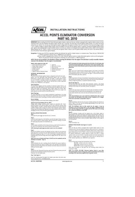
INSTALLATION INSTRUCTIONS<br />
ACCEL POINTS ELIMINATOR CONVERSION<br />
PART NO. <strong>2010</strong><br />
IMPORTANT: Before installing the ACCEL Points Eliminator <strong>Ignition</strong> System, make sure that your vehicle is equipped with an ignition ballast resistor (or loom<br />
resistance wire) in the wire between the ignition switch and the coil (+) terminal. One easy way to find the ignition ballast resistor is to check the service<br />
manual for your vehicle. You can test your stock ignition system voltage while the engine is at idle at the coil (+) terminal. If the measured voltage is within<br />
1-volt of battery voltage, an ignition ballast resistor must be installed in the wire from the ignition switch. In general, all vehicles equipped with the Delco<br />
point ignition were equipped with an ignition ballast resistor. If you find your vehicle is not equipped with an ignition ballast resistor, install an ACCEL <strong>Ignition</strong><br />
Ballast Resistor Part No. 150001 in series in the wire from the ignition switch. Failure to use an ignition ballast resistor will result in the eventual destruction<br />
of the ACCEL Points Eliminator <strong>Ignition</strong> Module.<br />
Exceptions: 1) Using one of ACCEL’s 4 specially matched coils eliminate the need for a ballast resistor or a resistance wire. These coils are: 140108, 8140<br />
or 8140C SuperStock Canister Coils, or 140009 HD E-core SuperCoil.<br />
2) If your vehicle is equipped with an ACCEL 275+/300+ Electronic <strong>Ignition</strong> Control or similar aftermarket ignition control, use the wiring specified<br />
for the particular controller, along with its matching coil, such as ACCEL 's 140019 SuperCoil.<br />
NOTE: This kit can be installed in the distributor without removing the distributor from the engine if the distributor is easily accessible. However,<br />
removal of the distributor from the engine is recommended.<br />
PARTS INCLUDED IN THIS KIT<br />
1 ACCEL Points Eliminator Module 1 Cable Tie<br />
1 Shutter Wheel, 2-piece set 2 Bolts, 8-32 x 3/4 Hex<br />
1 Distributor Wire Harness 2 Nuts, 8-32 Hex<br />
1 Female Connector 2 Flathead Screws, 8-32 x 1/4<br />
1 Mounting Plate 2 Screws, 6-32 x 3/16<br />
1 Capsule, Thermal Conductive Grease 1 Grommet<br />
GENERAL INFORMATION<br />
<strong>Ignition</strong> Coils:<br />
The ACCEL Points Eliminator <strong>Ignition</strong> System is designed to work with most stock<br />
ignition coils and aftermarket high performance ignition coils. For optimum<br />
performance in systems without an ACCEL 275+/300+ or similar ignition control,<br />
use one of ACCEL’s 4 specially matched coils eliminates the need for a ballast<br />
resistor or a resistance wire. These coils are: 140108, 8140 or 8140C SuperStock<br />
Canister Coils, 140009 HD E-core SuperCoil.<br />
Spark Plug Wires:<br />
To prevent false triggering and the possibility of premature ignition failures, use<br />
suppression type spark plug wire. We recommend spiral core ignition wire, such as<br />
ACCEL 8mm Spiral Core SuperStock, ACCEL 8.8mm Spiral Core, ACCEL 300+<br />
RaceWire or ACCEL 8mm Extreme 9000 <strong>Ignition</strong> Wire. Do NOT use a copper core<br />
spark plug wire set with the ACCEL Points Eliminator kit.<br />
Spark Plug Gaps:<br />
For street applications, use your engine manufacturer’s specifications. For racing<br />
applications, start with your engine manufacturer’s specifications, then experiment<br />
with and closely monitor various gaps to achieve maximum performance.<br />
Electric Welding:<br />
Unplug the distributor wire harness before welding on the vehicle<br />
Optional Circuit Guard Mallory Part No. 29371:<br />
Voltage spikes (voltage transients, power surges) are associated with "noisy"<br />
electrical systems from electrical defects such as worn alternator brushes, faulty<br />
voltage regulator, corroded or oxidized electrical connections and similar electrical<br />
problems. Voltage spikes damage the ACCEL Points Eliminator <strong>Ignition</strong> Module.<br />
Voltage spikes are clamped and regulated by the optional Mallory Circuit Guard from<br />
damaging the ACCEL Points Eliminator <strong>Ignition</strong> Module.<br />
INSTALLATION PROCEDURE<br />
Step 1<br />
Disconnect the point trigger wire from the coil (–) terminal.<br />
Step 2<br />
Locate the spark plug wire on the distributor cap that the engine timing is set from.<br />
See a service manual for these locations. Mark the distributor housing, in line with<br />
this spark plug wire position on the distributor cap.<br />
Step 3<br />
Turn the engine crankshaft until the timing mark lines up with the TDC (top dead center)<br />
mark on the timing tab. See a service manual for these locations.<br />
NOTE: Removing the spark plugs may make it easier to turn the crankshaft.<br />
Step 4<br />
Remove the distributor cap from the distributor and lay it aside. Do not remove the<br />
spark plug wires or coil wire. The rotor blade should point to the mark made on the<br />
distributor housing (from Step 2). If it is not, turn the engine crankshaft one full turn<br />
(repeating Step 3) until the timing mark lines up (again) with the TDC mark on the<br />
timing tab.<br />
NOTE: Once you are finished with Step 4, DO NOT turn the crankshaft until the<br />
distributor is installed – Step 12.<br />
Step 5<br />
Note the direction the rotor is pointing. Note the direction the vacuum chamber is<br />
pointing. Disconnect the vacuum chamber hose at the carburetor and temporarily<br />
plug this carburetor fitting. Remove the distributor hold down clamp and remove the<br />
distributor from the engine.<br />
Step 6<br />
Remove the rotor. Disconnect the primary point wire. Remove the primary wire and<br />
grommet from the distributor. Remove the points and the<br />
condenser from the breaker plate.<br />
NOTE: Occasionally, the breaker plate ground wire will interfere. Pry the breaker plate<br />
ground wire from the breaker plate, and disconnect it from vacuum chamber mounting<br />
screw. The ACCEL Points Eliminator system will operate without the breaker plate<br />
ground wire.<br />
Step 8<br />
Apply a thin coat of white thermal conductive grease to the bottom of the ACCEL<br />
Points Eliminator module. Install the ACCEL Points Eliminator module onto the<br />
mounting plate with two 6-32 x 3/16 screws. See Figure 1. Secure the three module<br />
wires to the breaker plate with a cable tie.<br />
Step 9<br />
Install the grommet in the hole in the distributor hosing where the primary point wire<br />
had previously fed through. Slide the three wires from the ACCEL Points Eliminator<br />
module, through the grommet, to outside the distributor housing.<br />
Step 10 (See Figure 2)<br />
Put the three wires from the ACCEL Points Eliminator module in the female<br />
connector: green wire in hole #1; brown wire in hole #2; red wire in hole #3. Plug the<br />
distributor wire harness into the female connector. See Figure 2.<br />
Step 11<br />
Install the two–piece shutter underneath the rotor drive plate and install two 8-32 bolts.<br />
The hex heads of the 8-32 bolts fits into the matching holes on the underside of the<br />
shutter wheel. Install the rotor on the rotor drive and install two 8-32 hex nuts. See<br />
Figure 1.<br />
NOTE: Some distributors use a rotor made from a flexible plastic. File or cut the<br />
rotor locator (on the bottom of the rotor) so that it measures 1/8" in length.<br />
Install rotor and shutter as described in Step 11.<br />
Step 12<br />
Install the distributor with the rotor and vacuum chamber pointing in the direction as<br />
noted in Step 5. The rotor must be pointing (approximately) at the mark on the<br />
distributor housing from Step 2.<br />
NOTE: The distributor must be fully seated into the engine. It may be<br />
necessary to turn the oil pump drive, or turn the engine crankshaft two full<br />
turns until the timing mark lines up (again) with the TDC mark on the timing<br />
tab, to allow the distributor to seat fully.<br />
Step 13<br />
Turn the distributor housing until the nearest slot on the shutter wheel is<br />
approximately in the center of the optics of the ACCEL Points Eliminator module. This<br />
will generally give timing close enough for starting purposes. The rotor must be<br />
pointing (approximately) at the mark on the distributor housing from Step 2. Put the<br />
distributor hold down clamp in place and tighten slightly, leaving it loose enough to<br />
turn the distributor.<br />
Step 14<br />
Install the distributor cap.<br />
WIRING PROCEDURE (See Figures 3, 4 and 5)<br />
Step 1<br />
Make sure that your vehicle is equipped with an ignition ballast resistor (or loom<br />
resistance wire) in the wire between the ignition switch and the coil (+) terminal. If<br />
you find your vehicle is not equipped with an ignition ballast resistor, install an ACCEL<br />
<strong>Ignition</strong> Ballast Resistor Part No. 150001 in series in the wire from the ignition switch.<br />
For optimum performance in systems without an ACCEL 275+/375+ or similar<br />
ignition control, use one of ACCEL's 4 specially matched coils which eliminates the<br />
need for a ballast resistor or a resistance wire. These coils are: 140108, 8140 or<br />
8140C Canister SuperStock coil, 140009 HD E-core SuperCoil.<br />
Step 2<br />
There are three wires coming from the distributor wire harness:<br />
RED WIRE: Connect to the coil (+) terminal.<br />
GREEN WIRE: Connect to the coil (–) terminal.<br />
BROWN WIRE: Connect to engine block ground.<br />
Clean away any grease, oil and paint from the mounting surface before the<br />
connection is made.<br />
NOTE: If an ACCEL 275+/300+ Electronic <strong>Ignition</strong> Control or any other<br />
aftermarket ignition control is being used, connect the distributor wire harness<br />
according to the instructions supplied with the ignition control.<br />
Step 7 (See Figure 1)<br />
Install the mounting plate flat against the breaker plate where the points were.<br />
Secure using two 8-32 x 1/4 flathead screws.<br />
ACCEL IGNITION www.mrgasket.com 1
DISTRIBUTOR TUNE–UP PARTS PART NO.<br />
DISTRIBUTOR CAP 120214<br />
ROTOR 130117<br />
SHUTTER WHEEL (Two Piece) 338<br />
ACCEL Points Eliminator Module 2005<br />
DISTRIBUTOR WIRE HARNESS 29349<br />
STARTING THE ENGINE<br />
CAUTION: Be sure all tools, wires and miscellaneous objects are clear of<br />
moving engine parts and extreme heat before starting the engine.<br />
Recheck all wires and connections to make sure they are correct. Check and clean,<br />
or replace spark plugs. If replacing spark plugs, use types recommended by the<br />
engine manufacturer.<br />
Step 1<br />
Connect a timing light. Find the area with the best view of the timing marks.<br />
Step 2<br />
Start engine. If it fails to start, rotate the distributor in small increments clockwise or<br />
counterclockwise until engine starts. Do not exceed more than ten degrees of<br />
distributor housing rotation in either direction.<br />
Step 3<br />
Set timing as recommended by engine manufacturer, then tighten distributor hold<br />
down clamp. Make sure timing is still correct. If timing has moved, repeat this procedure.<br />
Step 4<br />
Re-connect the vacuum hose between the vacuum chamber and the carburetor.<br />
FIGURE 3<br />
ACCEL POINTS ELIMINATOR WIRING DIAGRAM USING<br />
12V IGNITION FEED AND AN ACCEL 140108, 8140<br />
OR 8140C<br />
MUST USE<br />
SUPRESSOR COIL<br />
WIRE<br />
FIGURE 1<br />
( )<br />
+<br />
( )<br />
–<br />
IGNITION COIL<br />
NOTE: ACCEL 8140 COIL IS SHOWN<br />
FOR ILLUSTRATION PURPOSES.<br />
GREEN<br />
RED<br />
BROWN<br />
TO IGNITION SWITCH<br />
TO IGNITION 12V SWITCH<br />
DISTRIBUTOR<br />
DISTRIBUTOR WIRE<br />
HARNESS<br />
GROUND TO ENGINE BLOCK<br />
ACCEL POINTS<br />
ELIMINATOR MODULE<br />
FIGURE 4<br />
ACCEL POINTS ELIMINATOR WIRING DIAGRAM USING<br />
OEM PRIMARY RESISTANCE WIRE<br />
MUST USE<br />
SUPRESSOR COIL<br />
WIRE<br />
IGNITION COIL<br />
–<br />
+<br />
GREEN<br />
RED<br />
OEM PRIMARY<br />
RESISTANCE WIRE<br />
BROWN<br />
TO IGNITION SWITCH<br />
DISTRIBUTOR<br />
DISTRIBUTOR WIRE<br />
HARNESS<br />
FIGURE 5<br />
GROUND TO ENGINE BLOCK<br />
ACCEL POINTS ELIMINATOR WIRING DIAGRAM<br />
USING BALLAST RESISTOR<br />
FIGURE 2<br />
MUST USE<br />
SUPRESSOR COIL<br />
WIRE<br />
FEMALE<br />
CONNECTOR<br />
DISTRIBUTOR WIRE<br />
HARNESS<br />
IGNITION COIL<br />
RED<br />
BROWN<br />
GREEN<br />
3 2<br />
1<br />
INDEX RIB<br />
RED<br />
BROWN<br />
GREEN<br />
+<br />
–<br />
ACCEL BALLAST<br />
RESISTOR<br />
PART NO. 150001 OR<br />
OEM BALLAST<br />
GREEN<br />
RED<br />
BROWN<br />
TO IGNITION SWITCH<br />
DISTRIBUTOR<br />
DISTRIBUTOR WIRE<br />
HARNESS<br />
ACCEL IS A DIVISION OF THE MR. GASKET PERFORMANCE GROUP<br />
10601 MEMPHIS AVE. #12, CLEVELAND, OH 44144<br />
216.688.8300 FAX 216.688.8306<br />
GROUND TO ENGINE BLOCK<br />
FORM 1581A<br />
1/04<br />
Made in U.S.A.<br />
Printed in U.S.A.<br />
2 www.mrgasket.com


