

MSD 6520 Ignition Kit Installation Instructions - Jegs
MSD 6520 Ignition Kit Installation Instructions - Jegs
MSD 6520 Ignition Kit Installation Instructions - Jegs

You also want an ePaper? Increase the reach of your titles
YUMPU automatically turns print PDFs into web optimized ePapers that Google loves.
INSTALLATION INSTRUCTIONS<br />
PRESTART CHECK LIST<br />
• The only wires connected to the coil terminals are the <strong>MSD</strong> Orange to coil positive and<br />
Black to coil negative.<br />
• The small Red wire of the <strong>MSD</strong> is connected to a switched 12 volt source.<br />
• Confirm the cylinder select is in the proper position for your application.<br />
• The <strong>MSD</strong> power leads are connected directly to the battery positive and negative terminals.<br />
• The battery is connected and fully charged if not using an alternator.<br />
• The engine is equipped with at least one ground strap to the chassis.<br />
TROUBLESHOOTING<br />
Every <strong>MSD</strong> <strong>Ignition</strong> undergoes numerous quality control checks including a four hour burn-in test.<br />
If you experience a problem with your <strong>MSD</strong>, our research has shown that the majority of problems<br />
are due to improper installation or poor connections.<br />
The Troubleshooting section has several checks and tests you can perform to ensure proper<br />
installation and operation of the <strong>MSD</strong>. If you have any questions concerning your <strong>MSD</strong>, call our<br />
Customer Support Department at (915) 855-7123, 8 - 5 mountain time.<br />
LED<br />
The LED on the side of the <strong>MSD</strong> monitors several operating conditions of the <strong>MSD</strong>. If the<br />
LED indicates that there is a problem with the ignition system, follow the steps through the<br />
Troubleshooting section. The LED will appear to be on steady at above idle speeds when everything<br />
is functioning properly.<br />
• Flashes once per second if the battery supply voltage is low when under 3,300 rpm (while<br />
multiple sparking). This indicates a charging problem or poor connection.<br />
• It will flash approximately once per second if the battery input voltage is above 27 volts for<br />
a sustained amount of time.<br />
• The LED will flash for every trigger signal from the distributor or crank trigger. You can take<br />
advantage of this when statically setting the timing when using the White wire to trigger.<br />
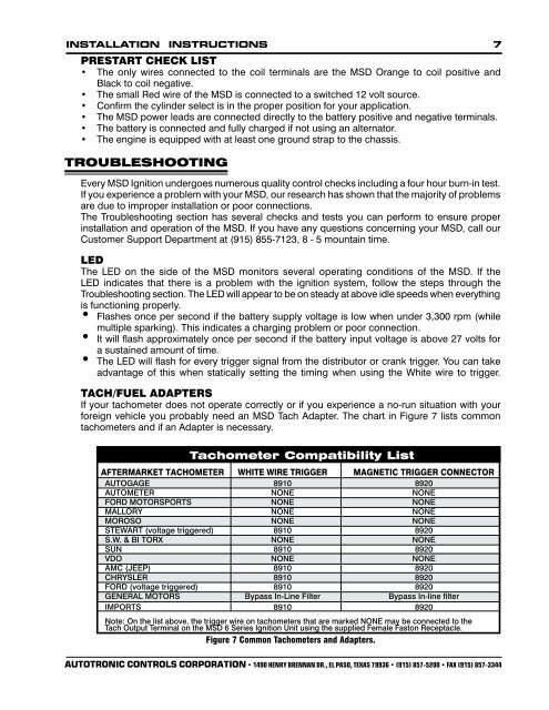
TACH/FUEL ADAPTERS<br />
If your tachometer does not operate correctly or if you experience a no-run situation with your<br />
foreign vehicle you probably need an <strong>MSD</strong> Tach Adapter. The chart in Figure 7 lists common<br />
tachometers and if an Adapter is necessary.<br />
<br />
Tachometer Compatibility List<br />
AFTERMARKET TACHOMETER WHITE WIRE TRIGGER MAGNETIC TRIGGER CONNECTOR<br />
AUTOGAGE 8910 8920<br />
AUTOMETER NONE NONE<br />
FORD MOTORSPORTS NONE NONE<br />
MALLORY NONE NONE<br />
MOROSO NONE NONE<br />
STEWART (voltage triggered) 8910 8920<br />
S.W. & BI TORX NONE NONE<br />
SUN 8910 8920<br />
VDO NONE NONE<br />
AMC (JEEP) 8910 8920<br />
CHRYSLER 8910 8920<br />
FORD (voltage triggered) 8910 8920<br />
GENERAL MOTORS Bypass In-Line Filter Bypass In-line filter<br />
IMPORTS 8910 8920<br />
Note: On the list above, the trigger wire on tachometers that are marked NONE may be connected to the<br />
Tach Output Terminal on the <strong>MSD</strong> 6 Series <strong>Ignition</strong> Unit using the supplied Female Faston Receptacle.<br />
Figure 7 Common Tachometers and Adapters.<br />
AUTOTRONIC CONTROLS CORPORATION • 1490 HENRY BRENNAN DR., EL PASO, TEXAS 79936 • (915) 857-5200 • FAX (915) 857-3344


