3100 Installation Guide - Janus International
3100 Installation Guide - Janus International
3100 Installation Guide - Janus International

You also want an ePaper? Increase the reach of your titles
YUMPU automatically turns print PDFs into web optimized ePapers that Google loves.
JANUS INTERNATIONAL<br />
1 866 562 2580<br />
www .janusintl.c o m<br />
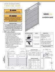
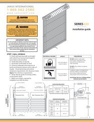
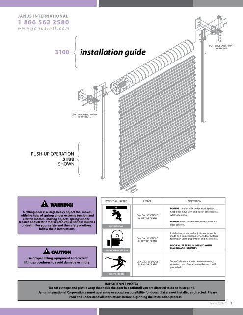
<strong>3100</strong> installation guide<br />
RIGHT DRIVE END SHOWN<br />
LH OPPOSITE<br />
LEFT TENSION END SHOWN<br />
RH OPPOSITE<br />
PUSH-UP OPERATION<br />
<strong>3100</strong><br />
SHOWN<br />
WARNING!<br />
A rolling door is a large heavy object that moves<br />
with the help of springs under extreme tension and<br />
electric motors. Moving objects, springs under<br />
tension and electric motors can cause serious injuries<br />
or death. For your safety and the safety of others,<br />
follow these instructions.<br />
CAUTION<br />
Use proper lifting equipment and correct<br />
lifting procedures to avoid damage or injury.<br />
POTENTIAL HAZARD EFFECT PREVENTION<br />
MOVING DOOR<br />
EXTREME SPRING TENSION<br />
CAN CAUSE SERIOUS<br />
INJURY OR DEATH<br />
CAN CAUSE SERIOUS<br />
INJURY OR DEATH<br />
CAN CAUSE SERIOUS<br />
BURNS OR DEATH<br />
DO NOT stand or walk under moving door.<br />
Keep door in full view and free of obstructions<br />
while operating.<br />
DO NOT allow children to operate the door or<br />
door controls.<br />
<strong>Installation</strong>, repairs and adjustments must be<br />
made by a trained rolling service door systems<br />
technician using proper tools and instructions.<br />
DOOR MUST BE FULLY OPENED WHEN<br />
MAKING ADJUSTMENTS.<br />
Turn off electrical power before removing<br />
operator cover. Operator must be electrically<br />
grounded.<br />
ELECTRIC SHOCK<br />
IMPORTANT NOTE:<br />
Do not cut tape and plastic wrap that holds the door in a roll until you are directed to do so in step 14B.<br />
<strong>Janus</strong> <strong>International</strong> Corporation cannot guarantee or accept responsibility for doors that are not installed as directed. Please<br />
read and understand all instructions before beginning the installation process.<br />
revised 3/1/13 1
SIDE ROOM REQUIREMENTS<br />
* All dimensions are taken from edge of opening<br />
OPERATION<br />
BACK<br />
OF<br />
GUIDE<br />
OUTSIDE OF<br />
BRACKET<br />
TENSIONER END<br />
OUTSIDE OF<br />
BRACKET<br />
DRIVE END<br />
(NON-TENSIONER)<br />
OUTSIDE OF<br />
HAND CHAIN<br />
DRIVE<br />
EACH END<br />
OF AXLE<br />
<strong>3100</strong><br />
DOOR<br />
SERIES<br />
Push-up<br />
Reduced Hand Chain<br />
4-1/4"<br />
4-1/4"<br />
5-7/8"<br />
5-7/8"<br />
5-7/8"<br />
6-5/8"<br />
8-1/8"<br />
8-3/4"<br />
8-3/4"<br />
Electric<br />
4-1/4"<br />
5-7/8"<br />
7-3/8"<br />
8-3/4"<br />
EDGE OF OPENING<br />
END OF AXLE CLEARANCE<br />
OUTSIDE OF TENSIONER<br />
BRACKET CLEARANCE<br />
EDGE OF OPENING<br />
END OF AXLE CLEARANCE<br />
OUTSIDE OF CHAIN DRIVE<br />
OUTSIDE OF DRIVE<br />
BRACKET CLEARANCE<br />
CLEARANCE<br />
CHARTS<br />
FIGURE 1<br />
Tensioner<br />
End Shown<br />
BACK OF<br />
GUIDE CLEARANCE<br />
Tensioner end and drive end<br />
can be installed at either<br />
end of door assembly.<br />
Drive End<br />
(Non-Tensioner)<br />
Shown<br />
BACK OF<br />
GUIDE CLEARANCE<br />
HEADROOM REQUIREMENTS<br />
OPENING<br />
HEIGHT<br />
VERTICAL<br />
HEADROOM<br />
HORIZONTAL<br />
HEADROOM<br />
HORIZONTAL<br />
HEADROOM<br />
THRU<br />
8'-0" 20" 20"<br />
OVER<br />
8'-0"<br />
THRU<br />
10'-0"<br />
OVER<br />
10'-0"<br />
THRU<br />
14'-0"<br />
OVER<br />
14'-0"<br />
THRU<br />
16'-0"<br />
OVER<br />
16'-0"<br />
THRU<br />
18'-0"<br />
OVER<br />
18'-0"<br />
THRU<br />
20'-0"<br />
21" 21"<br />
21-1/2" 21"<br />
22" 21"<br />
22" 22"<br />
22" 22"<br />
VERTICAL<br />
HEADROOM<br />
WALL<br />
OPENING<br />
HEIGHT<br />
2<br />
revised 3/1/13
STEP 1: WALL OPENING<br />
A. Check wall opening width and height and verify these measurements against size of door to be installed.<br />
B. Verify that jambs are plumb.<br />
C. Check floor and header for level.<br />
D. Check for adequate side clearance at jambs and clearance above and at sides of header. Check vertical and horizontal<br />
requirements. See Clearance charts figure 1 for minimum requirements.<br />
E. Verify that the guide mounting surface on the jamb is flush.<br />
F. Make sure all parts required for installation are with the door.<br />
STEP 2: MOUNTING PLATES (OPTIONAL EXCEPT FOR STEEL JAMBS)<br />
A. If door will install to steel jambs, mounting plates for the door brackets are required and may be welded<br />
or bolted to the jambs.<br />
B. Top of mounting plates should be located 10" above top of opening and be level with each other. Side of<br />
mounting plates should be even with edge of opening. If opening width is off, adjust locations accordingly.<br />
See figure 2.<br />
C. If mounting plates are bolted to jambs, do not use a flat washer between bolt and mounting plate. See figure 3.<br />
NOTE: DOOR DRIVE OPERATION MAY BE INSTALLED ON EITHER END OF DOOR ASSEMBLY.<br />
STEP 3: BRACKETS TO GUIDES<br />
A. Attach door brackets to guides, locating top surface of bracket 2" below top of guide. Use 2 each 1/4-20 x 5/8"<br />
carriage bolts, 1/4-20 serrated flange hex nuts and 1/4" flat washers per bracket for tensioner end and the<br />
non-tensioner (drive) end for push-up operation. See figures 5 and 6.<br />
B. For reduced hand chain drive end, install drive bracket with 2 each 1/4-20 x 1-3/4" carriage bolts, 1/4-20<br />
serrated flange hex nuts and 1/4" flat washers. Insert 1 each 1-1/4" O.D. x 3/4" long spacer tube between<br />
guide and bracket at each bolt location. See figure 7.<br />
C. For electric operation drive end, install drive bracket with 2 each 1/4-20 x 2-1/2" carriage bolts, 1/4-20 serrated<br />
flange hex nuts and 1/4" flat washers. Insert 2 each 1-1/4" O.D. x 3/4" long spacer tubes between guide and<br />
bracket at each bolt location. See figure 8.<br />
STEP 4: GUIDES AND BRACKETS TO JAMB<br />
A. Attach brackets and guides to jambs using fasteners shown in table 1.<br />
B. The guides should be mounted centered about the opening and spaced curtain width + 4" apart for opening widths<br />
through 12' or curtain width + 3-3/4" for opening widths over 12' through 16'. This spacing is measured from<br />
back of guide to back of guide. See figure 3. Both guides must be plumb.<br />
C. Once both guides have been correctly positioned, attach them to the jambs using the appropriate fastener at<br />
each hole location. See table 1 and figure 3.<br />
D. Check top surface of brackets to verify they are level with each other. If they are not, loosen the bracket-toguide<br />
attachment fasteners and slide bracket(s) vertically until level. Tighten bracket-to-guide fasteners.<br />
E. Install 3 bracket-to-jamb attachment fasteners for each bracket. See table 1.<br />
WARNING!<br />
DOOR CAN FALL IF BOTH BRACKETS ARE NOT SECURELY FASTENED TO THE JAMBS. ALL FASTENERS ATTACHING BRACKETS TO<br />
JAMBS MUST FIT SECURELY INTO A STRUCTURAL MEMBER OR SURFACE. IF DOOR FALLS, SERIOUS INJURY OR DEATH<br />
AND/OR DAMAGE TO DOOR CAN RESULT.<br />
TABLE 1: Wall Fasteners included for jamb attachment of Brackets and <strong>Guide</strong>s.<br />
ITEM<br />
JAMB<br />
FASTENERS<br />
DRILL SIZE<br />
Brackets<br />
Steel<br />
Concrete or Filled Block<br />
3/8-16 x 1-1/4” Hex Bolt and Nut<br />
3/8" x 1-3/4” Powers Wedge-Bolt<br />
7/16”<br />
Powers 01316<br />
<strong>Guide</strong>s<br />
Steel<br />
Concrete or Filled Block<br />
1/4" x 14 x1” TEKS Screw<br />
None<br />
3/8" x 4” Powers Wedge-Bolt 3/8” x 10” O.A.L.<br />
revised 3/1/13 3
FIGURE 2<br />
MOUNTING PLATE<br />
INSTALLATION<br />
MOUNTING PLATES TO BE LEVEL<br />
BOLT HEAD ORIENTATION<br />
NOT CRITICAL<br />
SERIES <strong>3100</strong><br />
MOUNTING PLATE<br />
(2 REQUIRED<br />
FOR STEEL<br />
JAMBS ONLY)<br />
10"<br />
SERIES <strong>3100</strong><br />
MOUNTING PLATE<br />
(2 REQUIRED<br />
FOR STEEL<br />
JAMBS ONLY)<br />
TOP OF OPENING<br />
MOUNTING PLATE EVEN<br />
WITH EDGE OF OPENING<br />
MOUNTING PLATE EVEN<br />
WITH EDGE OF OPENING<br />
EDGE OF OPENING<br />
EDGE OF OPENING<br />
FASTENER LOCATIONS<br />
FOR OPTION 3<br />
ATTACHMENT TO<br />
MINIMUM 14 GAUGE<br />
STEEL JAMBS<br />
2"<br />
FASTENER LOCATION<br />
FOR OPTION 1<br />
STEEL JAMBS<br />
2"<br />
SERIES <strong>3100</strong><br />
GUIDE CROSS<br />
SECTION SHOWN<br />
IN MOUNTING<br />
PLATE AREA<br />
4-1/4"<br />
MOUNTING PLATE BOLT<br />
CURTAIN WIDTH + 4"<br />
(OPENING WIDTHS THROUGH 12')<br />
CURTAIN WIDTH + 3-3/4"<br />
(OPENING WIDTHS OVER 12' THROUGH 16')<br />
4-1/4"<br />
FASTENER LOCATION<br />
FOR CONCRETE AND<br />
FILLED BLOCK JAMBS<br />
AND FOR OPTION 2<br />
STEEL JAMBS<br />
FIGURE 3<br />
GUIDE<br />
INSTALLATION<br />
WALL<br />
WALL<br />
WALL<br />
FIGURE 4<br />
TENSIONER<br />
END<br />
4<br />
revised 3/1/13<br />
CAST AXLE SUPPORT BRACKET - 1-5/16"<br />
HAND CHAIN OPERATION<br />
ONE EACH PER DOOR<br />
SERIES <strong>3100</strong><br />
STAMPED AXLE SUPPORT - 1-5/16"<br />
PUSH-UP & ELECTRIC OPERATION<br />
ONE EACH PER DOOR<br />
SERIES <strong>3100</strong><br />
TENSIONER ASSEMBLY - 1-5/16"<br />
ONE EACH PER DOOR<br />
SERIES <strong>3100</strong>
STEP 5: TENSIONER END<br />
A. Using tensioner assembly's spring roll pin located in knurled wheel, rotate upward in the direction that clears the axle.<br />
B. Slide tensioner assembly over axle, with arrow pointing toward wall. Release pin. See figures 4 and 5.<br />
WARNING!<br />
TENSIONER ASSEMBLY MUST BE ORIENTED ON AXLE WITH THE ARROW POINTING TOWARD THE WALL. IF THIS IS NOT DONE, IT WILL<br />
NOT OPERATE AS DESIGNED, WHICH MAY CAUSE SERIOUS INJURY OR DEATH DUE TO THE DOOR SUDDENLY LOSING SPRING TENSION<br />
AND RAPIDLY MOVING DOWNWARD.<br />
STEP 6: PUSH-UP NON-TENSIONER END<br />
A. Slide stamped axle support over axle, with arrow pointing toward wall. See figures 4 and 6.<br />
STEP 7: REDUCED CHAIN DRIVE END<br />
A. Fasten 63 tooth cast ring gear to drum using 3 each 3/8-16 x 1-1/2" grade 5 hex bolts and 3/8" lock washers.<br />
B. Install 2 each 3/8-16 x 1" square head setscrews in the threaded holes in the cast axle support bracket.<br />
These will be tightened against the axle later.<br />
C. Slide cast axle support bracket over axle. See figures 4 and 7.<br />
STEP 8: ELECTRIC DRIVE END<br />
A. Locate 3 each 1" O.D. x 2-3/8" long spacer tubes and 9" long x 2-5/8" offset struts between 72 tooth #41<br />
sprocket and drum. Attach sprocket with 3 each 3/8-16 x 3-1/2" grade 5 hex bolts and 3/8" lock washers.<br />
B. Slide stamped axle support over axle, with arrow pointing toward wall. See figures 4 and 8.<br />
STEP 9: LIFTING DOOR ASSEMBLY<br />
A. Orient door with bottom bar located at 12 o'clock position.<br />
B. Lift door assembly using a forklift that has padded forks in order to prevent damage to curtain.<br />
C. Position door on brackets with tensioner and axle support resting safely on top of bracket flange.<br />
D. Door should be positioned as close as possible to the header and still be able to rotate and clear bottom bar.<br />
E. Each end of door should be equal distance from the header and the curtain must be centered in the opening.<br />
WARNING!<br />
DO NOT ALLOW DOOR ASSEMBLY TO ROLL OFF BRACKETS OR MOVE SIDEWAYS OFF EDGE OF BRACKET. IF DOOR FALLS,<br />
SERIOUS INJURY OR DEATH AND/OR DAMAGE TO DOOR CAN RESULT.<br />
STEP 10: TENSIONER END<br />
A. Attach tensioner assembly to door bracket using 2 each 3/8-16 x 3/4" grade 5 hex bolts, 3/8" lock<br />
washers and 3/8" flat washers. See figures 4 and 5.<br />
STEP 11: PUSH-UP NON-TENSIONER END<br />
A. Attach stamped axle support to door bracket using 2 each 3/8-16 x 3/4" grade 5 hex bolts, 3/8" lock<br />
washers and 3/8" flat washers. See figures 4 and 6.<br />
STEP 12: REDUCED HAND CHAIN DRIVE END<br />
A. Attach cast axle support bracket to door bracket using 3/8-16 x 3/4" grade 5 hex bolt, 3/8" lock washer<br />
and 3/8" flat washer.<br />
B. Position chain hoist assembly on door bracket next to cast axle support and attach to door bracket using<br />
2 each 3/8-16 x 3/4" grade 5 hex bolts, 3/8" lock washers and 3/8" flat washers. The spur gear on the hoist<br />
will engage with the internal teeth of the cast ring gear on the end of the drum. See figure 7.<br />
C. Connect cast axle support bracket to side of chain hoist using 3/8-16 x 3/4" hex bolt and 3/8" lock washer.<br />
See figures 4 and 7.<br />
D. Feed hand chain over chain pocket wheel and through hoist. Connect ends of hand chain, being careful not<br />
to twist chain. Hand chain may be lengthened or shortened as necessary.<br />
E. Install hand chain keeper on wall or jamb.<br />
STEP 13: ELECTRIC DRIVE END<br />
A. Attach stamped axle support to door bracket using 2 each 3/8-16 x 3/4" grade 5 hex bolts, 3/8" lock<br />
washers and 3/8" flat washers. See figures 4 and 8.<br />
STEP 14: SETTING INITIAL SPRING TENSION<br />
A. Rotate door 1-1/2 revolutions in the direction that would send the bottom bar down through the guides.<br />
B. While firmly holding the door at the bottom bar, cut the tape and plastic wrap that holds the door in a coil.<br />
Direct the bottom bar down into the guides, stopping just past the head stop area.<br />
WARNING!<br />
EXTREME SPRING TENSION CAN CAUSE SERIOUS INJURY OR DEATH. INSTALLATION, REPAIRS AND ADJUSTMENTS MUST BE MADE BY<br />
A TRAINED ROLLING SERVICE DOOR SYSTEMS TECHNICIAN USING PROPER TOOLS AND INSTRUCTIONS.<br />
DOOR MUST BE FULLY OPEN WHEN MAKING ADJUSTMENTS.<br />
revised 3/1/13 5
BEARING<br />
MOUNTING PLATE<br />
(STEEL JAMBS ONLY)<br />
TENSIONER ASSEMBLY - 1-5/16"<br />
CARRIAGE BOLT<br />
1/4-20 X 5/8"<br />
FLAT WASHER 1/4"<br />
DOOR<br />
BRACKET<br />
DOOR ASSEMBLY<br />
SERRATED FLANGE<br />
HEX NUT 1/4-20<br />
HEADSTOP<br />
AXLE 1-5/16"<br />
DRUM 12"<br />
FLAT WASHER 3/8"<br />
LOCK WASHER 3/8"<br />
HEX BOLT - GRADE 5<br />
3/8-16 X 3/4"<br />
GUIDE<br />
SERIES <strong>3100</strong><br />
WIND LOAD RATED<br />
ALL OPERATIONS<br />
TENSIONER END<br />
ASSEMBLY DIAGRAM<br />
FIGURE 5<br />
BEARING<br />
STAMPED AXLE SUPPORT - 1-5/16"<br />
MOUNTING PLATE<br />
(STEEL JAMBS ONLY)<br />
CARRIAGE BOLT<br />
1/4-20 X 5/8"<br />
FLAT WASHER 1/4"<br />
DOOR<br />
BRACKET<br />
DOOR ASSEMBLY<br />
SERRATED FLANGE<br />
HEX NUT 1/4-20<br />
HEADSTOP<br />
AXLE 1-5/16"<br />
DRUM 12"<br />
FLAT WASHER 3/8"<br />
LOCK WASHER 3/8"<br />
SERIES <strong>3100</strong><br />
WIND LOAD RATED<br />
PUSH-UP OPERATION<br />
NON-TENSIONER END<br />
ASSEMBLY DIAGRAM<br />
FIGURE 6<br />
6<br />
revised 3/1/13<br />
HEX BOLT - GRADE 5<br />
3/8-16 X 3/4"<br />
GUIDE
CAST RING GEAR<br />
63 TOOTH<br />
BEARING<br />
HEX BOLT - GRADE 5<br />
3/8-16 X 1-1/2"<br />
HEX BOLT<br />
3/8-16 X 3/4"<br />
LOCK WASHER - 3/8"<br />
CHAIN HOIST<br />
ASSEMBLY<br />
CAST AXLE<br />
SUPPORT BRACKET<br />
1-5/16"<br />
AXLE 1-5/16"<br />
DRUM 12"<br />
DOOR ASSEMBLY<br />
MOUNTING PLATE<br />
(STEEL JAMBS ONLY)<br />
LOCK WASHER - 3/8"<br />
SQUARE HEAD CUP POINT<br />
SET SCREW 3/8-16 X 1"<br />
FLAT WASHER 1/4"<br />
DOOR<br />
BRACKET<br />
CARRIAGE BOLT<br />
1/4-20 X 1-3/4"<br />
SERRATED FLANGE<br />
HEX NUT 1/4-20<br />
HEADSTOP<br />
SPACER<br />
1-1/4" O.D. X 3/4" L<br />
SERIES <strong>3100</strong><br />
WIND LOAD RATED<br />
REDUCED HAND CHAIN OPERATION<br />
DRIVE END<br />
ASSEMBLY DIAGRAM<br />
FLAT<br />
WASHER 3/8"<br />
LOCK<br />
WASHER 3/8"<br />
GUIDE<br />
CHAIN KEEPER<br />
FIGURE 7<br />
HEX BOLT - GRADE 5<br />
3/8-16 X 3/4"<br />
BEARING<br />
72 TOOTH #41 SPROCKET<br />
MOUNTING PLATE<br />
(STEEL JAMBS ONLY)<br />
STAMPED AXLE<br />
SUPPORT - 1-5/16"<br />
SPACER<br />
1-1/4" O.D. X 3/4" L<br />
CARRIAGE BOLT<br />
1/4-20 X 2-1/2"<br />
AXLE 1-5/16"<br />
SPACER (3)<br />
1" O.D. X 2-3/8" L<br />
DRUM 12"<br />
DOOR ASSEMBLY<br />
FLAT WASHER 1/4"<br />
STRUT (3)<br />
9" L X 2-5/8" OFFSET<br />
DOOR<br />
BRACKET<br />
LOCK WASHER 3/8"<br />
HEADSTOP<br />
SERRATED FLANGE<br />
HEX NUT 1/4-20<br />
FLAT<br />
WASHER 3/8"<br />
HEX BOLT - GRADE 5<br />
3/8-16 X 3-1/2"<br />
SERIES <strong>3100</strong><br />
WIND LOAD RATED<br />
ELECTRIC OPERATION<br />
DRIVE END<br />
ASSEMBLY DIAGRAM<br />
LOCK<br />
WASHER 3/8"<br />
GUIDE<br />
FIGURE 8<br />
HEX BOLT - GRADE 5<br />
3/8-16 X 3/4"<br />
revised 3/1/13 7
STEP 15: HEAD STOPS<br />
A. Slide head stop from outside of each guide. See figures 5 through 8.<br />
B. Secure each head stop to guide with a 3/8-16 x 1/2” hex bolt and a 3/8” lock washer.<br />
STEP 16: SLIDE LOCK, STEP PLATE AND PULL ROPE<br />
A. Lower bottom bar and install slide lock and step plate using 2 each 1/4-20 x 1" hex bolts, 5/16-18 hex nuts,<br />
1/4" flat washers and 1/4-20 nylon insert hex nuts. Do this at both ends of bottom bar. See figure 9.<br />
B. Transfer the 1/4-20 x 1/2" carriage bolts and 1/4-20 serrated flange hex nuts that were removed from both<br />
ends of the bottom bar to the 2 holes at the center of the bottom bar and angle.<br />
C. For push-up operation only, install rope in one of the holes at the center of the horizontal leg of the bottom<br />
bar angle.<br />
DOOR CURTAIN<br />
SLIDE LOCK<br />
HEX BOLT<br />
1/4-20 X 1" STEP PLATE<br />
BOTTOM BAR ASSEMBLY<br />
FIGURE 9<br />
BOTTOM BAR<br />
NYLON INSERT NUT<br />
1/4-20<br />
ANGLE<br />
ASTRAGAL<br />
HEX NUT 5/16-18<br />
FLAT WASHER 1/4"<br />
STEP 17: POSITION DOOR<br />
A. Fully open door.<br />
B. At both ends of the door, slightly loosen all 3/8-16 x 3/4" hex bolts that go through the door bracket and<br />
connect to the tensioner, axle support and chain hoist.<br />
C. Push door assembly as close as possible toward header and still be able to rotate freely. Each end of door<br />
should be equal distance from the header and the curtain must be centered in the opening.<br />
D. Tighten securely all 3/8-16 x 3/4" hex bolts that were loosened in step 17B.<br />
E. Tighten all 3/8-16 square head setscrews in tensioner and axle support at both ends of door.<br />
STEP 18: CHECK DOOR OPERATION<br />
A. Lower and raise the door to test door operation and balance.<br />
B. If door is easy to close, but hard to open, increase spring tension (See step 19).<br />
C. If door is hard to close, but easy to open, decrease spring tension (See step 19).<br />
WARNING!<br />
DOOR MUST BE FULLY OPENED WHEN MAKING ADJUSTMENTS.<br />
STEP 19: ADJUST SPRING TENSION (if required)<br />
A. Loosen all 3/8-16 square head setscrews in tensioner and axle support at both ends of door.<br />
B. At tensioner end, place pipe wrench around end of axle so that pulling down on the handle will rotate the axle to<br />
increase spring tension.<br />
C. To increase spring tension, pull down on pipe wrench. The tensioner will automatically grip the axle and hold<br />
the new tension setting.<br />
D. To decrease spring tension, momentarily pull down on pipe wrench and then lift the spring roll pin on the<br />
tensioner's knurled wheel. Gently let up on pipe wrench, allowing the axle to rotate to reduce the tension.<br />
While holding the new tension, release the tensioner's spring roll pin. The tensioner will now grip the axle<br />
and hold the new tension setting.<br />
E. Tighten all 3/8-16 square head setscrews in tensioner and axle support at both ends of door.<br />
F. Remove pipe wrench and operate door.<br />
G. Repeat steps 19A through 19F as necessary.<br />
8<br />
STEP 20: WARNING LABEL<br />
A. Install warning label at a readable height on the drive side door guide or jamb.<br />
revised 3/1/13