Mathematical Models for Control of Aircraft and Satellites - NTNU
Mathematical Models for Control of Aircraft and Satellites - NTNU
Mathematical Models for Control of Aircraft and Satellites - NTNU

You also want an ePaper? Increase the reach of your titles
YUMPU automatically turns print PDFs into web optimized ePapers that Google loves.
MATHEMATICAL MODELS FOR CONTROL OF<br />
AIRCRAFT AND SATELLITES<br />
THOR I. FOSSEN<br />
Pr<strong>of</strong>essor <strong>of</strong> Guidance, Navigation <strong>and</strong> <strong>Control</strong><br />
Centre <strong>for</strong> Autonomous Marine Operations <strong>and</strong> Systems<br />
Department <strong>of</strong> Engineering Cybernetics<br />
Norwegian University <strong>of</strong> Science <strong>and</strong> Technology<br />
April 2013<br />
3rd edition<br />
Copyright c○1998-2013 Department <strong>of</strong> Engineering Cybernetics, <strong>NTNU</strong>.<br />
1st edition published February 1998.<br />
2nd edition published January 2011.<br />
3rd edition published April 2013.
Contents<br />
Figures<br />
iii<br />
1 Introduction 1<br />
2 <strong>Aircraft</strong> Modeling 3<br />
2.1 Definition <strong>of</strong> <strong>Aircraft</strong> State-Space Vectors . . . . . . . . . . . . . . . . . . . . 3<br />
2.2 Body-Fixed Coordinate Systems <strong>for</strong> <strong>Aircraft</strong> . . . . . . . . . . . . . . . . . . 4<br />
2.2.1 Rotation matrices <strong>for</strong> wind <strong>and</strong> stability axes . . . . . . . . . . . . . 5<br />
2.3 <strong>Aircraft</strong> Equations <strong>of</strong> Motion . . . . . . . . . . . . . . . . . . . . . . . . . . 6<br />
2.3.1 Kinematic equations <strong>for</strong> translation . . . . . . . . . . . . . . . . . . . 6<br />
2.3.2 Kinematic equations <strong>for</strong> attitude . . . . . . . . . . . . . . . . . . . . 7<br />
2.3.3 Rigid-body kinetics . . . . . . . . . . . . . . . . . . . . . . . . . . . . 7<br />
2.3.4 Sensors <strong>and</strong> measurement systems . . . . . . . . . . . . . . . . . . . . 8<br />
2.4 Perturbation Theory (Linear Theory) . . . . . . . . . . . . . . . . . . . . . . 8<br />
2.4.1 Definition <strong>of</strong> nominal <strong>and</strong> perturbation values . . . . . . . . . . . . . 9<br />
2.4.2 Linearization <strong>of</strong> the rigid-body kinetics . . . . . . . . . . . . . . . . . 9<br />
2.4.3 Linear state-space model based using wind <strong>and</strong> stability axes . . . . . 11<br />
2.5 Decoupling in Longitudinal <strong>and</strong> Lateral Modes . . . . . . . . . . . . . . . . . 12<br />
2.5.1 Longitudinal equations . . . . . . . . . . . . . . . . . . . . . . . . . . 13<br />
2.5.2 Lateral equations . . . . . . . . . . . . . . . . . . . . . . . . . . . . . 13<br />
2.6 Aerodynamic Forces <strong>and</strong> Moments . . . . . . . . . . . . . . . . . . . . . . . 14<br />
2.6.1 Longitudinal aerodynamic <strong>for</strong>ces <strong>and</strong> moments . . . . . . . . . . . . . 16<br />
2.6.2 Lateral aerodynamic <strong>for</strong>ces <strong>and</strong> moments . . . . . . . . . . . . . . . . 16<br />
2.7 Propeller Thrust . . . . . . . . . . . . . . . . . . . . . . . . . . . . . . . . . 17<br />
2.8 Aerodynamic Coeffi cients . . . . . . . . . . . . . . . . . . . . . . . . . . . . . 18<br />
2.8.1 Aerodynamic <strong>for</strong>ces <strong>and</strong> moments . . . . . . . . . . . . . . . . . . . . 19<br />
2.8.2 Drag coeffi cient . . . . . . . . . . . . . . . . . . . . . . . . . . . . . . 20<br />
2.8.3 Lift coeffi cient . . . . . . . . . . . . . . . . . . . . . . . . . . . . . . . 21<br />
2.8.4 Side<strong>for</strong>ce coeffi cient . . . . . . . . . . . . . . . . . . . . . . . . . . . . 21<br />
2.8.5 Rolling moment coeffi cient . . . . . . . . . . . . . . . . . . . . . . . . 21<br />
2.8.6 Pitching moment coeffi cient . . . . . . . . . . . . . . . . . . . . . . . 22<br />
2.8.7 Yawing moment coeffi cient . . . . . . . . . . . . . . . . . . . . . . . . 23<br />
2.8.8 Equations <strong>of</strong> motion including aerodynamic coeffi cients . . . . . . . . 23<br />
2.9 St<strong>and</strong>ard <strong>Aircraft</strong> Maneuvers . . . . . . . . . . . . . . . . . . . . . . . . . . 23<br />
i
ii<br />
CONTENTS<br />
2.9.1 Dynamic equation <strong>for</strong> coordinated turn (bank-to-turn) . . . . . . . . 24<br />
2.9.2 Dynamic equation <strong>for</strong> altitude control . . . . . . . . . . . . . . . . . . 25<br />
2.10 <strong>Aircraft</strong> Stability Properties . . . . . . . . . . . . . . . . . . . . . . . . . . . 26<br />
2.10.1 Longitudinal stability analysis . . . . . . . . . . . . . . . . . . . . . . 27<br />
2.10.2 Lateral stability analysis . . . . . . . . . . . . . . . . . . . . . . . . . 28<br />
2.11 Design <strong>of</strong> flight control systems . . . . . . . . . . . . . . . . . . . . . . . . . 29<br />
3 Satellite Modeling 31<br />
3.1 Attitude Model . . . . . . . . . . . . . . . . . . . . . . . . . . . . . . . . . . 31<br />
3.1.1 Euler’s 2nd Axiom applied to satellites . . . . . . . . . . . . . . . . . 31<br />
3.1.2 Skew-symmetric representation <strong>of</strong> the satellite model . . . . . . . . . 32<br />
3.2 Actuator Dynamics . . . . . . . . . . . . . . . . . . . . . . . . . . . . . . . . 32<br />
3.3 Design <strong>of</strong> Satellite Attitude <strong>Control</strong> Systems . . . . . . . . . . . . . . . . . . 34<br />
3.3.1 Nonlinear quaternion set-point regulator . . . . . . . . . . . . . . . . 34<br />
3.3.2 PD-controller <strong>of</strong> Wen <strong>and</strong> Kreutz-Delago (1991) . . . . . . . . . . . . 35<br />
4 Matlab Simulation <strong>Models</strong> 37<br />
4.1 Boeing-767 . . . . . . . . . . . . . . . . . . . . . . . . . . . . . . . . . . . . . 37<br />
4.1.1 Longitudinal model . . . . . . . . . . . . . . . . . . . . . . . . . . . . 37<br />
4.1.2 Lateral model . . . . . . . . . . . . . . . . . . . . . . . . . . . . . . . 38<br />
4.2 F-16 Fighter . . . . . . . . . . . . . . . . . . . . . . . . . . . . . . . . . . . . 38<br />
4.2.1 Longitudinal model . . . . . . . . . . . . . . . . . . . . . . . . . . . . 39<br />
4.3 F2B Bristol Fighter . . . . . . . . . . . . . . . . . . . . . . . . . . . . . . . . 40<br />
4.3.1 Lateral model . . . . . . . . . . . . . . . . . . . . . . . . . . . . . . . 41<br />
4.4 <strong>NTNU</strong> student cube-satellite . . . . . . . . . . . . . . . . . . . . . . . . . . . 41
List <strong>of</strong> Figures<br />
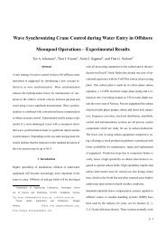
1.1 Sketch showing a modern fighter aircraft (Stevens <strong>and</strong> Lewis 1992). . . . . . 1<br />
2.1 Definition <strong>of</strong> aircraft body axes, generalized velocities, <strong>for</strong>ces, moments <strong>and</strong><br />
Euler angles (McLean 1990). . . . . . . . . . . . . . . . . . . . . . . . . . . . 4<br />
2.2 Definition <strong>of</strong> stability <strong>and</strong> wind axes <strong>for</strong> an aircraft (Stevens <strong>and</strong> Lewis 1992). 5<br />
2.3 <strong>Control</strong> inputs <strong>for</strong> conventional aircraft. Notice that the two ailerons can be<br />
controlled by using one control input: δ A = 1/2(δ AL + δ AR ). . . . . . . . . . 14<br />
2.4 Lift <strong>and</strong> drag as a function <strong>of</strong> angle <strong>of</strong> attack. . . . . . . . . . . . . . . . . . 22<br />
2.5 <strong>Aircraft</strong> longitudinal eigenvalue configuration plotted in the complex plane. . 28<br />
3.1 The NUTS CubeSat project at <strong>NTNU</strong>- Courtesy to http://nuts.cubesat.no/ 31<br />
4.1 Schematic drawing <strong>of</strong> the Bristol F.2B Fighter (McRuer et al 1973). . . . . . 40<br />
iii
iv<br />
LIST OF FIGURES
Chapter 1<br />
Introduction<br />
This booklet is a collection <strong>of</strong> lecture notes used in the course TTK4109 Guidance <strong>and</strong> <strong>Control</strong><br />
<strong>of</strong> Vehicles, which is given at the Department <strong>of</strong> Engineering Cybernetics, <strong>NTNU</strong>. The<br />
kinematic <strong>and</strong> kinetic equations <strong>of</strong> a marine craft (ships, high-speed craft <strong>and</strong> underwater<br />
vehicles) can be modified to describe aircraft <strong>and</strong> satellites by minor adjustments <strong>of</strong> notation<br />
<strong>and</strong> assumptions. Consequently, the vectorial notation introduced in the two Wiley<br />
textbooks:<br />
Fossen, T. I. (1994). Guidance <strong>and</strong> <strong>Control</strong> <strong>of</strong> Ocean Vehicles<br />
Fossen, T. I. (2011). H<strong>and</strong>book <strong>of</strong> Marine Craft Hydrodynamics <strong>and</strong> Motion <strong>Control</strong><br />
is used to describe the aircraft <strong>and</strong> satellite equations <strong>of</strong> motion.<br />
Figure 1.1: Sketch showing a modern fighter aircraft (Stevens <strong>and</strong> Lewis 1992).<br />
The booklet is organized according to:<br />
• Chapter 2: <strong>Aircraft</strong> Modeling<br />
• Chapter 3: Satellite Modeling<br />
• Chapter 4: Matlab Simulation <strong>Models</strong><br />
1
2 CHAPTER 1. INTRODUCTION<br />
Other useful references on flight control are:<br />
Blakelock, J. H. (1991). <strong>Aircraft</strong> <strong>and</strong> Missiles (John Wiley & Sons Ltd.)<br />
Etkin, B. <strong>and</strong> L. D. Reid (1996). Dynamics <strong>of</strong> Flight: Stability <strong>and</strong> <strong>Control</strong><br />
Wiley & Sons Ltd.)<br />
(John<br />
Fortescue, P., G. Swinerd <strong>and</strong> J. Stark (2011). Spacecraft Systems Engineering (John<br />
Wiley & Sons Ltd.)<br />
Hughes, P. C. (1986). Spacecraft Attitude Dynamics (John Wiley & Sons Ltd.)<br />
McLean, D. (1990). Automatic Flight <strong>Control</strong> Systems (Prentice Hall Inc.)<br />
McRuer, D., D. Ashkenas <strong>and</strong> A. I. Graham (1973). <strong>Aircraft</strong> Dynamics <strong>and</strong> Automatic<br />
<strong>Control</strong> (Princeton University Press)<br />
Nelson, R. C. (1998). Flight Stability <strong>and</strong> Automatic <strong>Control</strong> (McGraw-Hill Int.)<br />
Roskam, J. (1999). Airplane Flight Dynamics <strong>and</strong> Automatic Flight <strong>Control</strong>s (Darcorporation)<br />
Schmidt, D. K. (2012). Modern Flight Dynamics (McGraw-Hill Int.)<br />
Stevens, B. L. <strong>and</strong> F. L. Lewis (2003). <strong>Aircraft</strong> <strong>Control</strong> <strong>and</strong> Simulation (John Wiley<br />
& Sons Ltd.)<br />
In<strong>for</strong>mation about the graduate coursesTTK4109 Guidance <strong>and</strong> <strong>Control</strong> <strong>of</strong> Vehicles <strong>and</strong><br />
TK8109 Advanced Topics in Guidance <strong>and</strong> Navigation are found on the Wiki-pages<br />
URL: http://www.itk.ntnu.no/emner/ttk4190<br />
URL: http://www.itk.ntnu.no/emner/tk8109<br />
Thor I. Fossen<br />
Trondheim —3 April 2013
Chapter 2<br />
<strong>Aircraft</strong> Modeling<br />
This chapter gives an introduction to aircraft modeling. The equations <strong>of</strong> motion are linearized<br />
using perturbation theory <strong>and</strong> the final results are state-space models <strong>for</strong> the longitudinal<br />
<strong>and</strong> lateral motions. The models can be used <strong>for</strong> aircraft simulation <strong>and</strong> design <strong>of</strong><br />
flight control systems.<br />
2.1 Definition <strong>of</strong> <strong>Aircraft</strong> State-Space Vectors<br />
The aircraft generalized velocity vector is defined according to (see Figure 2.1):<br />
2<br />
ν :=<br />
6<br />
4<br />
2<br />
η :=<br />
6<br />
4<br />
U<br />
V<br />
W<br />
P<br />
Q<br />
R<br />
3<br />
X E<br />
Y E<br />
Z E , h<br />
Φ<br />
Θ<br />
Ψ<br />
2<br />
=<br />
7 6<br />
5 4<br />
3<br />
=<br />
7 6<br />
5 4<br />
longitudinal (<strong>for</strong>ward) velocity<br />
lateral (transverse) velocity<br />
vertical velocity<br />
roll rate<br />
pitch rate<br />
yaw rate<br />
2<br />
Earth-fixed x-position<br />
Earth-fixed y-position<br />
Earth-fixed z-position (axis downwards), altitude<br />
roll angle<br />
pitch angle<br />
yaw angle<br />
3<br />
7<br />
5<br />
3<br />
7<br />
5<br />
(2.1)<br />
(2.2)<br />
Forces <strong>and</strong> moments are defined in a similar manner:<br />
2 3 2<br />
X longitudinal <strong>for</strong>ce<br />
Y<br />
transverse <strong>for</strong>ce<br />
Z<br />
6 L<br />
:=<br />
vertical <strong>for</strong>ce<br />
7 6 roll moment<br />
4 M 5 4 pitch moment<br />
N yaw moment<br />
3<br />
7<br />
5<br />
(2.3)<br />
Comment 1: Notice that the capital letters L, M, N <strong>for</strong> the moments are different from<br />
3
4 CHAPTER 2. AIRCRAFT MODELING<br />
Figure 2.1: Definition <strong>of</strong> aircraft body axes, generalized velocities, <strong>for</strong>ces, moments <strong>and</strong> Euler<br />
angles (McLean 1990).<br />
those used <strong>for</strong> marine craft—that is, K, M, N. The reason <strong>for</strong> this is that L is reserved as<br />
length parameter <strong>for</strong> ships <strong>and</strong> underwater vehicles.<br />
Comment 2: For aircraft it is common to use capital letters <strong>for</strong> the states U, V, W, etc.<br />
while it is common to use small letters <strong>for</strong> marine craft.<br />
2.2 Body-Fixed Coordinate Systems <strong>for</strong> <strong>Aircraft</strong><br />
For aircraft it is common to use the following body-fixed coordinate systems:<br />
• BODY axes, superscript b<br />
• STABILITY axes, superscript s<br />
• WIND axes, superscript w<br />
The axis systems are shown in Figure 2.2 where the angle <strong>of</strong> attack α <strong>and</strong> sideslip angle β<br />
are defined as:<br />
tan(α) := W U<br />
(2.4)<br />
sin(β) := V V T<br />
(2.5)<br />
where<br />
V T = √ U 2 + V 2 + W 2 (2.6)
2.2. BODY-FIXED COORDINATE SYSTEMS FOR AIRCRAFT 5<br />
Figure 2.2: Definition <strong>of</strong> stability <strong>and</strong> wind axes <strong>for</strong> an aircraft (Stevens <strong>and</strong> Lewis 1992).<br />
is the total speed <strong>of</strong> the aircraft. Aerodynamic effects are classified according to the Mach<br />
number:<br />
M := V T<br />
a<br />
(2.7)<br />
where a = 340 m/s = 1224 km/h is the speed <strong>of</strong> sound in air at a temperature <strong>of</strong> 20 o C on<br />
the ocean surface. The following terminology is used <strong>for</strong> varying speed:<br />
Subsonic speed M < 1.0<br />
Transonic speed 0.8 ≤ M ≤ 1.2<br />
Supersonic speed 1.0 ≤ M ≤ 5.0<br />
Hypersonic speed 5.0 ≤ M<br />
An aircraft will break the sound barrier at M = 1.0 <strong>and</strong> this is clearly heard as a sharp<br />
crack. If you fly at low altitude <strong>and</strong> break the sound barrier, windows in building will break<br />
due to pressure-induced waves.<br />
2.2.1 Rotation matrices <strong>for</strong> wind <strong>and</strong> stability axes<br />
The relationship between vectors expressed in different coordinate systems can be derived<br />
using rotation matrices. The BODY axes are first rotated a negative sideslip angle −β about<br />
the z-axis. The new coordinate system is then rotated a positive angle <strong>of</strong> attack α about<br />
the new y-axis such that the resulting x-axis points in the direction <strong>of</strong> the total speed V T .<br />
The first rotation defines the WIND axes while the second rotation defines the STABILITY
6 CHAPTER 2. AIRCRAFT MODELING<br />
axes. This can be mathematically expressed as:<br />
2<br />
cos(β) sin(β)<br />
3<br />
0<br />
p w = R z,−β p s = 4 − sin(β) cos(β) 0 5 p s (2.8)<br />
2<br />
0 0 1<br />
3<br />
cos(α) 0 sin(α)<br />
p s = R y,α p b = 4 0 1 0 5 p b (2.9)<br />
− sin(α) 0 cos(α)<br />
The rotation matrix becomes:<br />
Hence,<br />
R w b = R z,−β R y,α (2.10)<br />
p w = R w b p b (2.11)<br />
⇕<br />
p w =<br />
⇕<br />
p w =<br />
2<br />
4<br />
2<br />
4<br />
cos(β) sin(β) 0<br />
− sin(β) cos(β) 0<br />
0 0 1<br />
3 2<br />
5 4<br />
cos(α) 0 sin(α)<br />
0 1 0<br />
− sin(α) 0 cos(α)<br />
cos(α) cos(β) sin(β) sin(α) cos(β)<br />
− cos(α) sin(β) cos(β) − sin(α) sin(β)<br />
− sin(α) 0 cos(α)<br />
3<br />
3<br />
5 p b (2.12)<br />
5 p b (2.13)<br />
This gives the following relationship between the velocities in body <strong>and</strong> wind axes:<br />
2<br />
v b = 4<br />
Consequently,<br />
U<br />
V<br />
W<br />
3<br />
2<br />
5 = (R w b ) ⊤ v w = R ⊤ y,αR ⊤ 4<br />
z,−β<br />
V T<br />
0<br />
0<br />
3<br />
2<br />
5 = 4<br />
U = V T cos(α) cos(β)<br />
V = V T sin(β)<br />
W = V T sin(α) cos(β)<br />
V T cos(α) cos(β)<br />
V T sin(β)<br />
V T sin(α) cos(β)<br />
3<br />
5 (2.14)<br />
(2.15)<br />
2.3 <strong>Aircraft</strong> Equations <strong>of</strong> Motion<br />
2.3.1 Kinematic equations <strong>for</strong> translation<br />
The kinematic equations <strong>for</strong> translation <strong>and</strong> rotation <strong>of</strong> a body-fixed coordinate system<br />
BODY with respect to a local geographic coordinate system NED (North-East-Down) can<br />
be expressed in terms or the Euler angles:<br />
2<br />
4<br />
Ẏ E<br />
ŻE<br />
5 = R n b<br />
Ẋ E<br />
3<br />
2<br />
4<br />
U<br />
V<br />
W<br />
3<br />
2<br />
5 = R z,Ψ R y,Θ R x,Φ<br />
4<br />
U<br />
V<br />
W<br />
3<br />
5 (2.16)
2.3. AIRCRAFT EQUATIONS OF MOTION 7<br />
Exp<strong>and</strong>ing this expression gives:<br />
2 3 2<br />
Ẋ E cΨ −sΨ 0<br />
4 Ẏ E<br />
5 = 4 sΨ cΨ 0<br />
ŻE 0 0 1<br />
2<br />
4<br />
3 2<br />
5 4<br />
cΘ 0 sΘ<br />
0 1 0<br />
−sΘ 0 cΘ<br />
3 2<br />
5 4<br />
1 0 0<br />
0 cΦ −sΦ<br />
0 sΦ cΦ<br />
3 2<br />
5 4<br />
⇕ (2.17)<br />
3 2<br />
3 2 3<br />
Ẋ E cΨcΘ −sΨcΦ + cΨsΘsΦ sΨsΦ + cΨcΦsΘ U<br />
Ẏ E<br />
5 = 4 sΨcΘ cΨcΦ + sΦsΘsΨ −cΨsΦ + sΘsΨcΦ 5 4 V 5<br />
ŻE −sΘ cΘsΦ cΘcΦ<br />
W<br />
2.3.2 Kinematic equations <strong>for</strong> attitude<br />
U<br />
V<br />
W<br />
3<br />
5<br />
The attitude is given by:<br />
2<br />
P<br />
3 2<br />
4 Q 5 = 4<br />
R<br />
˙Φ<br />
0<br />
0<br />
3 2<br />
5 + R ⊤ 4<br />
x,Φ<br />
0<br />
˙Θ<br />
0<br />
3<br />
2<br />
5 + R ⊤ x,ΦR ⊤ 4<br />
y,Θ<br />
0<br />
0<br />
˙Ψ<br />
3<br />
5 (2.18)<br />
which gives:<br />
2<br />
4<br />
˙Φ<br />
˙Θ<br />
˙Ψ<br />
3<br />
2<br />
5 = 4<br />
1 sΦtΘ cΦtΘ<br />
0 cΦ −sΦ<br />
0 sΦ/cΘ cΦ/cΘ<br />
3 2<br />
5 4<br />
P<br />
Q<br />
R<br />
3<br />
5 , cΘ ≠ 0 (2.19)<br />
2.3.3 Rigid-body kinetics<br />
The aircraft rigid-body kinetics can be expressed as (Fossen 1994, 2011):<br />
m( ˙ν 1 + ν 2 × ν 1 ) = τ 1 (2.20)<br />
I CG ˙ν 2 + ν 2 × (I CG ν 2 ) = τ 2 (2.21)<br />
where ν 1 := [U, V, W ] T , ν 2 := [P, Q, R] T , τ 1 := [X, Y, Z] T <strong>and</strong> τ 2 := [L, M, N] T . It is assumed<br />
that the coordinate system is located in the aircraft center <strong>of</strong> gravity (CG). The<br />
resulting model is written:<br />
M RB ˙ν + C RB (ν)ν = τ RB (2.22)<br />
where<br />
M RB =<br />
<br />
<br />
mI3×3 O 3×3<br />
mS(ν2 ) O<br />
, C<br />
O 3×3 I RB (ν) =<br />
3×3<br />
CG O 3×3 −S(I CG<br />
ν 2 )<br />
<br />
(2.23)<br />
3<br />
The inertia tensor is defined as (assume that I xy = I yz = 0 which corresponds to xz−plane<br />
symmetry):<br />
2<br />
I x 0 −I xz<br />
−I xz 0 I z<br />
I CG := 4 0 I y 0 5 (2.24)<br />
The <strong>for</strong>ces <strong>and</strong> moments acting on the aircraft can be expressed as:<br />
τ RB = −g(η) + τ (2.25)
8 CHAPTER 2. AIRCRAFT MODELING<br />
where τ is a generalized vector that includes aerodynamic <strong>and</strong> control <strong>for</strong>ces. The gravitational<br />
<strong>for</strong>ce f G = [0 0 mg] T acts in the CG (origin <strong>of</strong> the body-fixed coordinate system) <strong>and</strong><br />
this gives the following vector expressed in NED:<br />
2<br />
3<br />
mg sin(Θ)<br />
<br />
−mg cos(Θ) sin(Φ)<br />
g(η) = −(R n fG<br />
b )⊤ =<br />
−mg cos(Θ) cos(Φ)<br />
O 3×1 6 0<br />
(2.26)<br />
7<br />
4 0 5<br />
0<br />
Hence, the aircraft model can be written in matrix <strong>for</strong>m as:<br />
or in component <strong>for</strong>m:<br />
M RB ˙ν + C RB (ν)ν + g(η) = τ (2.27)<br />
m( ˙U + QW − RV + g sin(Θ)) = X<br />
m( ˙V + UR − W P − g cos(Θ) sin(Φ)) = Y<br />
m(Ẇ + V P − QU − g cos(Θ) cos(Φ)) = Z<br />
I x P˙<br />
− I xz (Ṙ + P Q) + (I z − I y )QR = L (2.28)<br />
I y ˙Q + I xz (P 2 − R 2 ) + (I x − I z )P R = M<br />
I z Ṙ − I xz P ˙ + (I y − I x )P Q + I xz QR = N<br />
2.3.4 Sensors <strong>and</strong> measurement systems<br />
It is common that aircraft sensor systems are equipped with three accelerometers. If the<br />
accelerometers are located in the CG, the measurement equations take the following <strong>for</strong>m:<br />
a xCG = X m = ˙U + QW − RV + g sin(Θ) (2.29)<br />
a yCG = Y m = ˙V + UR − W P − g cos(Θ) sin(Φ) (2.30)<br />
a zCG = Z m<br />
= Ẇ + V P − QU − g cos(Θ) cos(Φ) (2.31)<br />
In addition to these sensors, an aircraft is equipped with gyros, magnetometers <strong>and</strong> a sensor<br />
<strong>for</strong> altitude h <strong>and</strong> wind speed V T . These sensors are used in inertial navigation systems (INS)<br />
which again use a Kalman filter to compute estimates <strong>of</strong> U, V, W, P, Q <strong>and</strong> R as well as the<br />
Euler angles Φ,Θ <strong>and</strong> Ψ. Other measurement systems that are used onboard aircraft are<br />
global navigation satellite systems (GNSS), radar <strong>and</strong> sensors <strong>for</strong> angle <strong>of</strong> attack.<br />
2.4 Perturbation Theory (Linear Theory)<br />
The nonlinear equations <strong>of</strong> motion can be linearized by using perturbation theory. This is<br />
illustrated below.
2.4. PERTURBATION THEORY (LINEAR THEORY) 9<br />
2.4.1 Definition <strong>of</strong> nominal <strong>and</strong> perturbation values<br />
According to linear theory it is possible to write the states as the sum <strong>of</strong> a nominal value<br />
(usually constant) <strong>and</strong> a perturbation (deviation from the nominal value). Moreover,<br />
Total state = Nominal value + Perturbation<br />
The following definitions are made:<br />
2 3 2 3<br />
2<br />
X 0 δX<br />
Y 0<br />
δY<br />
τ := τ 0 + δτ =<br />
Z 0<br />
6 L 0<br />
+<br />
δZ<br />
7 6 δL<br />
, ν := ν 0 + δν =<br />
7<br />
6<br />
4 M 0<br />
5 4 δM 5<br />
4<br />
N 0 δN<br />
3<br />
U 0<br />
V 0<br />
W 0<br />
P 0<br />
7<br />
Q 0<br />
5<br />
R 0<br />
2<br />
+<br />
6<br />
4<br />
u<br />
v<br />
w<br />
p<br />
q<br />
r<br />
3<br />
7<br />
5<br />
(2.32)<br />
Similar, the angles are defined according to:<br />
2 3 2<br />
Θ<br />
4 Φ 5 := 4<br />
Ψ<br />
3 2<br />
Θ 0<br />
Φ 0<br />
5 + 4<br />
Ψ 0<br />
θ<br />
φ<br />
ψ<br />
3<br />
5 (2.33)<br />
Consequently, a linearized state-space model will consist <strong>of</strong> the following states u, v, w, p, q, r, θ, φ<br />
<strong>and</strong> ψ.<br />
2.4.2 Linearization <strong>of</strong> the rigid-body kinetics<br />
The rigid-body kinetics can be linearized by using perturbation theory.<br />
Equilibrium condition<br />
If the aerodynamic <strong>for</strong>ces <strong>and</strong> moments, velocities, angles <strong>and</strong> control inputs are expressed<br />
as nominal values <strong>and</strong> perturbations τ = τ 0 + δτ , ν = ν 0 + δν <strong>and</strong> η = η 0 + δη, the aircraft<br />
equilibrium point will satisfy (it is assumed that ˙ν 0 = 0):<br />
This can be exp<strong>and</strong>ed according to:<br />
C RB (ν 0 )ν 0<br />
+ g(η 0<br />
) = τ 0 (2.34)<br />
m(Q 0 W 0 − R 0 V 0 + g sin(Θ 0 )) = X 0<br />
m(U 0 R 0 − P 0 W 0 − g cos(Θ 0 ) sin(Φ 0 )) = Y 0<br />
m(P 0 V 0 − Q 0 U 0 − g cos(Θ 0 ) cos(Φ 0 )) = Z 0<br />
(I z − I y )Q 0 R 0 − P 0 Q 0 I xz = L 0 (2.35)<br />
(P 2 0 − R 2 0)I xz + (I x − I z )P 0 R 0 = M 0<br />
(I y − I x )P 0 Q 0 + Q 0 R 0 I xz = N 0
10 CHAPTER 2. AIRCRAFT MODELING<br />
Perturbed equations<br />
The perturbed equations—that is, the linearized equations <strong>of</strong> motion are usually derived by<br />
a 1st-order Taylor series expansion about the nominal values. Alternatively, it is possible<br />
to substitute (2.32) <strong>and</strong> (2.35) into (2.27) <strong>and</strong> neglect higher-order terms <strong>of</strong> the perturbed<br />
states. This is illustrated <strong>for</strong> the first degree <strong>of</strong> freedom (DOF):<br />
Example 1 (Linearization <strong>of</strong> surge using perturbation theory)<br />
m[ ˙U + QW − RV + g sin(Θ)] = X<br />
⇓ (2.36)<br />
m[ ˙U 0 + ˙u + (Q 0 + q)(W 0 + w) − (R 0 + r)(V 0 + v) + g sin(Θ 0 + θ)] = X 0 + δX<br />
This can be written:<br />
sin(Θ 0 + θ) = sin(Θ 0 ) cos(θ) + cos(Θ 0 ) sin(θ) θ small<br />
≈ sin(Θ 0 ) + cos(Θ 0 )θ (2.37)<br />
Since ˙U 0 = 0 <strong>and</strong><br />
m(Q 0 W 0 − R 0 V 0 + g sin(Θ 0 )) = X 0 (2.38)<br />
Equation (2.36) is reduced to:<br />
m[ ˙u + Q 0 w + W 0 q + wq − R 0 v − V 0 r − vr + g cos(Θ 0 )θ] = δX (2.39)<br />
If it is assumed that the 2nd-order terms wq <strong>and</strong> vr are negligible, the linearized model<br />
becomes:<br />
□<br />
m[ ˙u + Q 0 w + W 0 q − R 0 v − V 0 r + g cos(Θ 0 )θ] = δX (2.40)<br />
Linear state-space model <strong>for</strong> aircraft<br />
If all DOFs are linearized, the following state-space model is obtained:<br />
m[ ˙u + Q 0 w + W 0 q − R 0 v − V 0 r + g cos(Θ 0 )θ] = δX<br />
m[ ˙v + U 0 r + R 0 u − W 0 p − P 0 w − g cos(Θ 0 ) cos(Φ 0 )φ + g sin(Θ 0 ) sin(Φ 0 )θ] = δY<br />
m[ẇ + V 0 p + P 0 v − U 0 q − Q 0 u + g cos(Θ 0 ) sin(Φ 0 )φ + g sin(Θ 0 ) cos(Φ 0 )θ] = δZ<br />
I x ṗ − I xz ṙ + (I z − I y )(Q 0 r + R 0 q) − I xz (P 0 q + Q 0 p) = δL (2.41)<br />
I y ˙q + (I x − I z )(P 0 r + R 0 p) − 2I xz (R 0 r + P 0 p) = δM<br />
I z ṙ − I xz ṗ + (I y − I x )(P 0 q + Q 0 p) + I xz (Q 0 r + R 0 q) = δN<br />
This can be expressed in matrix <strong>for</strong>m as:<br />
M RB ˙ν + N RB ν + Gη = τ (2.42)
2.4. PERTURBATION THEORY (LINEAR THEORY) 11<br />
where<br />
M RB =<br />
N RB =<br />
G =<br />
2<br />
6<br />
4<br />
2<br />
6<br />
4<br />
2<br />
6<br />
4<br />
3<br />
m 0 0<br />
m 0 0 3×3<br />
0 0 m<br />
I x 0 −I xz<br />
7<br />
0 3×3 0 I y 0 5<br />
−I xz 0 I z<br />
3<br />
0 −mR 0 mQ 0 0 mW 0 −mV 0<br />
mR 0 0 −P 0 −W 0 0 U 0<br />
−mQ 0 mP 0 0 mV 0 −mU 0 0<br />
−I xz Q 0 (I z − I y )R 0 − I xz P 0 (I z − I y )Q 0<br />
7<br />
0 3×3 (I x − I z )R 0 −2I xz P 0 (I x − I z )P 0 − 2I xz R 0<br />
5<br />
(I y − I x )Q 0 (I y − I x )P 0 + I xz R 0 I xz Q 0<br />
3<br />
0 mg cos(Θ 0 ) 0<br />
0 3×3 −mg cos(Θ 0 ) cos(Φ 0 ) mg sin(Θ 0 ) sin(Φ 0 ) 0<br />
mg cos(Θ 0 ) sin(Φ 0 ) mg sin(Θ 0 ) cos(Φ 0 ) 0<br />
7<br />
0 3×3 0 3×3<br />
5<br />
In addition to this, the kinematic equations must be linearized.<br />
2.4.3 Linear state-space model based using wind <strong>and</strong> stability axes<br />
An alternative state-space model is obtained by using α <strong>and</strong> β as states. If it is assumed<br />
that α <strong>and</strong> β are small such that cos(α) ≈ 1 <strong>and</strong> sin(β) ≈ β, Equation (2.15) can be written<br />
as:<br />
U = V T U = V T<br />
V = V T β<br />
W = V T α<br />
Furthermore, the state-space vector:<br />
2 3 2<br />
u<br />
β<br />
x =<br />
α<br />
6 p<br />
=<br />
7 6<br />
4 q 5 4<br />
r<br />
⇒<br />
β = V V T<br />
α = W V T<br />
(2.43)<br />
surge velocity<br />
sideslip angle<br />
angle <strong>of</strong> attack<br />
roll rate<br />
pitch rate<br />
yaw rate<br />
3<br />
7<br />
5<br />
(2.44)<br />
is chosen to describe motions in 6 DOF. The relationship between the body-fixed velocity<br />
vector:<br />
ν = [u, v, w, p, q, r] T (2.45)<br />
<strong>and</strong> the new state-space vector x can be written as:<br />
ν = Tx = diag{1, V T , V T , 1, 1, 1, 1}x (2.46)
12 CHAPTER 2. AIRCRAFT MODELING<br />
where V T > 0. If the total speed is V T = U 0 = constant (linear theory), it is seen that:<br />
˙α = 1<br />
V T<br />
ẇ (2.47)<br />
˙β = 1<br />
V T<br />
˙v (2.48)<br />
˙V T = 0 (2.49)<br />
If nonlinear theory is applied, the following differential equations are obtained:<br />
˙α =<br />
UẆ − W ˙U<br />
U 2 + W 2 (2.50)<br />
˙β = ˙V V T − V ˙V T<br />
V 2<br />
T cos β (2.51)<br />
˙V T = U ˙U + V ˙V + W Ẇ<br />
V T<br />
(2.52)<br />
In the linear case it is possible to trans<strong>for</strong>m the body-fixed state-space model:<br />
to<br />
where<br />
˙ν = Fν + Gu (2.53)<br />
ẋ = Ax + Bu (2.54)<br />
A = T −1 FT, B = T −1 G (2.55)<br />
For ˙V T ≠ 0 this trans<strong>for</strong>mation is much more complicated. The linear state-space trans<strong>for</strong>mation<br />
is commonly used by aircraft manufactures. An example is the Boeing B-767 model<br />
(see Chapter 4).<br />
2.5 Decoupling in Longitudinal <strong>and</strong> Lateral Modes<br />
For an aircraft it is common to assume that the longitudinal modes (DOFs 1, 3 <strong>and</strong> 5)<br />
are decoupled from the lateral modes (DOFs 2, 4 <strong>and</strong> 6). The key assumption is that the<br />
fuselage is slender—that is, the length is much larger than the width <strong>and</strong> the height <strong>of</strong> the<br />
aircraft. It is also assumed that the longitudinal velocity is much larger than the vertical<br />
<strong>and</strong> transversal velocities.<br />
In order to decouple the rigid-body kinetics (2.41) in longitudinal <strong>and</strong> lateral modes it<br />
will be assumed that the states v, p, r <strong>and</strong> φ are negligible in the longitudinal channel while<br />
u, w, q <strong>and</strong> θ are negligible when considering the lateral channel. This gives two sub-systems:
2.5. DECOUPLING IN LONGITUDINAL AND LATERAL MODES 13<br />
2.5.1 Longitudinal equations<br />
Kinetics:<br />
2<br />
4<br />
m[ ˙u + Q 0 w + W 0 q + g cos(Θ 0 )θ] = δX<br />
m[ẇ − U 0 q − Q 0 u + g sin(Θ 0 ) cos(Φ 0 )θ] = δZ (2.56)<br />
3 2<br />
m 0 0<br />
0 m 0 5 4<br />
0 0 I y<br />
˙u<br />
ẇ<br />
˙q<br />
3<br />
2<br />
5 + 4<br />
0 mQ 0 mW 0<br />
−mQ 0 0 −mU 0<br />
0 0 0<br />
2<br />
4<br />
I y ˙q = δM<br />
mg cos(Θ 0 )<br />
mg sin(Θ 0 ) cos(Φ 0 )<br />
0<br />
3 2<br />
5 4<br />
3<br />
u<br />
w<br />
q<br />
3<br />
5 +<br />
2<br />
5 θ = 4<br />
δX<br />
δZ<br />
δM<br />
3<br />
5<br />
(2.57)<br />
Kinematics:<br />
˙θ = q (2.58)<br />
2.5.2 Lateral equations<br />
Kinetics:<br />
2<br />
4<br />
m 0 0<br />
3 2<br />
0 I x −I xz<br />
5 4<br />
m[ ˙v + U 0 r − W 0 p − g cos(Θ 0 ) cos(Φ 0 )φ] = δY<br />
I x ṗ − I xz ṙ + (I z − I y )Q 0 r − I xz Q 0 p = δL (2.59)<br />
I z ṙ − I xz ṗ + (I y − I x )Q 0 p + I xz Q 0 r = δN<br />
˙v<br />
ṗ<br />
ṙ<br />
3<br />
2<br />
5 + 4<br />
0 −mW 0 mU 0<br />
3<br />
0 −I xz Q 0 (I z − I y )Q 0<br />
5<br />
2<br />
4<br />
2<br />
4<br />
−mg cos(Θ 0 ) cos(Φ 0 )<br />
0<br />
0<br />
v<br />
p<br />
r<br />
3<br />
3<br />
5 +<br />
2<br />
5 φ = 4<br />
δY<br />
δL<br />
δN<br />
3<br />
5<br />
(2.60)<br />
Kinematics:<br />
˙φ<br />
˙ψ<br />
<br />
=<br />
1 tan(Θ0 )<br />
0 1/ cos(Θ 0 )<br />
p<br />
r<br />
<br />
(2.61)
14 CHAPTER 2. AIRCRAFT MODELING<br />
Figure 2.3: <strong>Control</strong> inputs <strong>for</strong> conventional aircraft. Notice that the two ailerons can be<br />
controlled by using one control input: δ A = 1/2(δ AL + δ AR ).<br />
2.6 Aerodynamic Forces <strong>and</strong> Moments<br />
In the <strong>for</strong>thcoming sections, the following abbreviations <strong>and</strong> notation will be used to describe<br />
the aerodynamic coeffi cients:<br />
X index =<br />
Y index =<br />
Z index =<br />
∂X L<br />
∂ index index = ∂L<br />
∂ index<br />
∂Y<br />
∂ index<br />
M index = ∂M<br />
∂ index<br />
∂Z<br />
∂ index<br />
N index = ∂N<br />
∂ index<br />
In order to illustrate how control surfaces influence the aircraft, an aircraft equipped with<br />
the following control inputs will be considered (see Figure 2.3):
2.6. AERODYNAMIC FORCES AND MOMENTS 15<br />
δ T Thrust Jet/propeller<br />
δ E Elevator<br />
<strong>Control</strong> surfaces on the rear <strong>of</strong> the aircraft used <strong>for</strong> pitch <strong>and</strong><br />
altitude control<br />
δ A Aileron<br />
Hinged control surfaces attached to the trailing edge <strong>of</strong> the wing used<br />
<strong>for</strong> roll/bank control<br />
δ F Flaps<br />
Hinged surfaces on the trailing edge <strong>of</strong> the wings used <strong>for</strong> braking<br />
<strong>and</strong> bank-to-turn<br />
δ R Rudder Vertical control surface at the rear <strong>of</strong> the aircraft used <strong>for</strong> turning<br />
A conventional aircraft has control surfaces such as ailerons δ A , elevators δ E , flaps δ F <strong>and</strong><br />
rudders δ R . A positive deflection <strong>of</strong> the control surfaces are to give a negative aerodynamic<br />
moment on the aircraft. Some <strong>of</strong> the control surfaces, like the ailerons, deflects simultaneously<br />
in an asymmetric manner. If an aircraft has two ailerons δ AL <strong>and</strong> δ AR , the aileron<br />
deflection is computed by:<br />
δ A = 1 2 (δ A R<br />
− δ AL ) (2.62)<br />
Other control surfaces, such as elevators, deflect symmetrically. If an aircraft has two elevators<br />
δ EL <strong>and</strong> δ ER , the elevator deflections become:<br />
δ E = 1 2 (δ E R<br />
+ δ EL ) (2.63)<br />
Linear theory<br />
The number <strong>of</strong> aerodynamic coeffi cients is reduced if linear theory is assumed. The control<br />
inputs <strong>and</strong> aerodynamic <strong>for</strong>ces <strong>and</strong> moments can be written as:<br />
τ = −M F ˙ν − N F ν + Bu (2.64)<br />
where −M F is aerodynamic added mass, −N F is aerodynamic damping <strong>and</strong> B is a matrix<br />
describing the actuator configuration including the <strong>for</strong>ce coeffi cients. The actuator dynamics<br />
is modeled by a 1st-order system:<br />
˙u = T −1 (u c − u) (2.65)<br />
where u c is comm<strong>and</strong>ed input, u is the actual control input produced by the actuators <strong>and</strong><br />
T = diag{T 1 , T 2 , ..., T r } is a diagonal matrix <strong>of</strong> positive time constants. Substitution <strong>of</strong> (2.64)<br />
into the model (2.42) gives:<br />
(M RB + M F ) ˙ν + (N RB<br />
+ N F<br />
)ν + Gη = Bu<br />
M ˙ν + Nν + Gη = Bu<br />
⇕ (2.66)<br />
The matrices M <strong>and</strong> N are defined as M = M RB + M F <strong>and</strong> N = N RB + N F<br />
. The linearized<br />
kinematics takes the following <strong>for</strong>m:<br />
The resulting state-space models are:<br />
˙η = J ν ν + J η η (2.67)
16 CHAPTER 2. AIRCRAFT MODELING<br />
Linear state-space model with actuator dynamics<br />
2<br />
4<br />
˙η<br />
˙ν<br />
˙u<br />
3<br />
2<br />
5 = 4<br />
3<br />
J η J ν 0<br />
−M −1 G −M −1 N M −1 B 5<br />
0 0 −T −1<br />
2<br />
4<br />
η<br />
ν<br />
u<br />
3<br />
2<br />
5 + 4<br />
3<br />
0<br />
0 5 u c (2.68)<br />
T −1<br />
Linear state-space model neglecting the actuator dynamics<br />
<br />
J<br />
= η<br />
˙η˙ν −M −1 G<br />
J ν<br />
−M −1 N<br />
η<br />
ν<br />
<br />
+<br />
0<br />
M −1 B<br />
<br />
u (2.69)<br />
2.6.1 Longitudinal aerodynamic <strong>for</strong>ces <strong>and</strong> moments<br />
McLean [7] expresses the longitudinal <strong>for</strong>ces <strong>and</strong> moments as:<br />
2<br />
4<br />
dX<br />
dZ<br />
dM<br />
3<br />
2<br />
5 = 4<br />
3<br />
X ˙u Xẇ X ˙q<br />
Z ˙u Zẇ Z ˙q<br />
5<br />
M ˙u Mẇ M ˙q<br />
2<br />
4<br />
˙u<br />
ẇ<br />
˙q<br />
3<br />
5 + 4<br />
2<br />
4<br />
2<br />
3<br />
X u X w X q<br />
Z u Z w Z q<br />
5<br />
M q M w M q<br />
3 2<br />
X δT X δE X δF<br />
Z δT<br />
Z δE Z δF<br />
5 4<br />
M δT M δE M δF<br />
2<br />
4<br />
u<br />
w<br />
q<br />
3<br />
δ T<br />
3<br />
δ E<br />
5<br />
5 +<br />
(2.70)<br />
which corresponds to the matrices −M F , −N F <strong>and</strong> B in (2.64). If the aircraft cruise speed<br />
U 0 = constant, then δ T = 0. Altitude can be controlled by using the elevators δ E . Flaps δ F<br />
can be used to reduce the speed during l<strong>and</strong>ing. The flaps can also be used to turn harder<br />
<strong>for</strong> instance by moving one flap while the other is kept at the zero position. This is common<br />
in bank-to-turn maneuvers. For conventional aircraft the following aerodynamic coeffi cients<br />
can be neglected:<br />
X ˙u , X q , Xẇ, X δE , Z ˙u , Zẇ, M ˙u (2.71)<br />
Hence, the model <strong>for</strong> altitude control reduces to:<br />
2<br />
4<br />
dX<br />
dZ<br />
dM<br />
3<br />
2<br />
5 = 4<br />
3<br />
0 0 X ˙q<br />
0 0 Z ˙q<br />
5<br />
0 Mẇ M ˙q<br />
2<br />
4<br />
˙u<br />
ẇ<br />
˙q<br />
3<br />
2<br />
5 + 4<br />
3<br />
X u X w 0<br />
Z u Z w Z q<br />
5<br />
M q M w M q<br />
2<br />
4<br />
u<br />
w<br />
q<br />
3<br />
2<br />
5 + 4<br />
3<br />
X δE<br />
Z δE<br />
5 δ E (2.72)<br />
M δE<br />
If the actuator dynamics is important, aerodynamic coeffi cients such as X˙δT<br />
, X˙δE<br />
, ... must<br />
be included in the model.<br />
2.6.2 Lateral aerodynamic <strong>for</strong>ces <strong>and</strong> moments<br />
The lateral model takes the <strong>for</strong>m [7]:
2.7. PROPELLER THRUST 17<br />
2<br />
4<br />
dY<br />
dL<br />
dN<br />
3<br />
2<br />
5 = 4<br />
Y ˙v Yṗ Yṙ<br />
L ˙v Lṗ Lṙ<br />
N ˙v Nṗ Nṙ<br />
3 2<br />
5 4<br />
˙v<br />
ṗ<br />
ṙ<br />
3<br />
2<br />
5 + 4<br />
3<br />
Y v Y p Y r<br />
L v L p L r<br />
5<br />
N v N p N r<br />
2<br />
4<br />
v<br />
p<br />
r<br />
3<br />
2<br />
5 + 4<br />
Y δA Y δR<br />
3<br />
L δA L δR<br />
<br />
5 δA<br />
δ R<br />
(2.73)<br />
which corresponds to the matrices −M F , −N F <strong>and</strong> B in (2.64). For conventional aircraft<br />
the following aerodynamic coeffi cients can be neglected:<br />
This gives:<br />
Y ˙v , Y p , Yṗ, Y r , Yṙ, Y δA ,L ˙v , Lṙ, N ˙v , Nṙ (2.74)<br />
2<br />
4<br />
dY<br />
dL<br />
dN<br />
3<br />
2<br />
5 = 4<br />
0 0 0<br />
0 Lṗ 0<br />
0 Nṗ 0<br />
3 2<br />
5 4<br />
˙v<br />
ṗ<br />
ṙ<br />
3<br />
2<br />
5 + 4<br />
3<br />
Y v 0 0<br />
L v L p L r<br />
5<br />
N v N p N r<br />
2<br />
4<br />
v<br />
p<br />
r<br />
3<br />
2<br />
5 + 4<br />
3<br />
0 Y δR<br />
<br />
L δA<br />
L δR<br />
5 δA<br />
δ<br />
N δA N R<br />
δR<br />
(2.75)<br />
2.7 Propeller Thrust<br />
The thrust from a propeller can be modeled as:<br />
where<br />
T Thrust <strong>for</strong>ce [N]<br />
K t Thrust coeffi cient<br />
ρ Density <strong>of</strong> air [kg/m 3 ]<br />
n Propeller angular velocity [rad/s]<br />
D Propeller diameter [m]<br />
T = K t ρn 2 D 4 (2.76)<br />
Assuming that the trust <strong>for</strong>ce acts in the horizontal plane <strong>of</strong> {b}, <strong>and</strong> parallel with the<br />
x b -axis, it can be expressed in {b} as:<br />
2 3 2 3<br />
X t T<br />
ft b = 4 Y t<br />
5 = 4 0 5 (2.77)<br />
Z t 0<br />
3<br />
3<br />
If the line <strong>of</strong> action <strong>of</strong> the thrust is not directed through CO, it will in addition generate an<br />
applied moment given by<br />
2<br />
L t<br />
N t<br />
2<br />
0<br />
m b t = 4 M t<br />
5 = r b t/b × ft b = S(r b t/b)ft<br />
b<br />
−T r ty<br />
= 4 T r tz<br />
5 (2.78)
18 CHAPTER 2. AIRCRAFT MODELING<br />
where r b t/b = [r t x<br />
, r ty , r tz ] ⊤ is the location <strong>of</strong> the propeller with respect to CO.<br />
Sometimes the effects due to the rotating mass caused by the propeller must be considered<br />
as an applied moment. This is because the equations <strong>of</strong> motion has been derived by assuming<br />
that the aircraft is a rigid body with no internal moving parts. The applied moment due to<br />
the rotating mass caused by the propeller is given by:<br />
m b p =<br />
i d<br />
dt hb p (2.79)<br />
where h b p is the angular momentum <strong>of</strong> the rotating mass, <strong>and</strong> is given in {b} as:<br />
2<br />
h b p = 4<br />
I p Ω p<br />
0<br />
0<br />
3<br />
5 (2.80)<br />
where I p is the inertia <strong>of</strong> the rotating mass <strong>and</strong> Ω p is the angular velocity. Assuming the<br />
angular velocity <strong>of</strong> the rotating mass is constant:<br />
2<br />
m b p = 4<br />
L p<br />
3<br />
M p<br />
5 =<br />
i d<br />
dt hb p =<br />
b d<br />
dt hb p + ω b b/n × h b p<br />
= ω b b/n × h b p = S(ω b b/n)h b p<br />
2 3<br />
0<br />
= 4 I p Ω p R<br />
−I p Ω p Q<br />
5 (2.81)<br />
The total <strong>for</strong>ces <strong>and</strong> moments due to thrust, τ t are:<br />
<br />
τ t =<br />
f b t<br />
S(r b t/g )f b t + S(ω b b/n )hb p<br />
<br />
(2.82)<br />
2.8 Aerodynamic Coeffi cients<br />
Different methods can be used to estimate the aerodynamic coeffi cients such as wind tunnel<br />
experiments or system identification based on logged experimental data from the aircraft.<br />
The aircraft equations <strong>of</strong> motion can be quite simple if the aircraft is not highly maneuverable.<br />
The more maneuverable aircraft, the more coeffi cients are needed to accurately<br />
describe the aerodynamic <strong>for</strong>ces <strong>and</strong> moments.<br />
The aerodynamic coeffi cients are usually linear at small angles <strong>of</strong> angle <strong>of</strong> attack <strong>and</strong><br />
sideslip. The most important parameters used to describe an airfoil are:<br />
b<br />
c<br />
¯c<br />
S<br />
AR = b 2 /S<br />
Wing span (tip to tip)<br />
Wing chord (varies along span)<br />
Mean aerodynamic chord<br />
Total wing area<br />
Aspect ratio
2.8. AERODYNAMIC COEFFICIENTS 19<br />
<strong>Aircraft</strong> with delta-shaped wings <strong>of</strong>ten have a low-aspect ratio, AR. A low-aspect ratio<br />
permits very high roll rates, but have a greatly reduced lift-over-drag. High lift-over-drag<br />
gives an aircraft that has effective cruise per<strong>for</strong>mance, that is passenger jets.<br />
The aerodynamic <strong>for</strong>ces <strong>and</strong> moments are <strong>of</strong>ten proportional to the freestream mass<br />
density, ρ a , <strong>and</strong> the square <strong>of</strong> the freestream airspeed, V T . It is thus convenient to define the<br />
dynamic pressure, ¯q, which is later used to calculate the aerodynamic <strong>for</strong>ces <strong>and</strong> moments:<br />
2.8.1 Aerodynamic <strong>for</strong>ces <strong>and</strong> moments<br />
¯q = 1 2 ρ aV 2<br />
T (2.83)<br />
The aerodynamic <strong>for</strong>ces <strong>and</strong> moments acting on an aircraft can be parametrized as:<br />
2 3 2 3<br />
X a C X<br />
fa b = 4 Y a<br />
5 = ¯qS 4 C Y<br />
5 (2.84)<br />
Z a C z<br />
2<br />
m b a = 4<br />
L a<br />
3<br />
M a<br />
5 = ¯qS<br />
2<br />
4<br />
bC l<br />
3<br />
¯cC m<br />
5 (2.85)<br />
where the aerodynamic coeffi cients C X <strong>and</strong> C Z <strong>of</strong>ten are replaced by expressions that are<br />
functions <strong>of</strong> the drag coeffi cient C D <strong>and</strong> the lift coeffi cient C L (see Figure 2.4). Positive drag<br />
<strong>and</strong> lift coeffi cients are directed along the −x s <strong>and</strong> −z s stability axes, respectively, such that:<br />
2<br />
4<br />
C D<br />
3<br />
0<br />
C<br />
5 = R s b<br />
2<br />
= 4<br />
2<br />
4<br />
3<br />
−C X<br />
0 5<br />
−C Z<br />
cos(α) 0 sin(α)<br />
0 1 0<br />
− sin(α) 0 cos(α)<br />
3 2<br />
5 4<br />
−C X<br />
3<br />
0 5 (2.86)<br />
Hence, the aerodynamic <strong>for</strong>ces can then be rewritten as:<br />
2 3 2 3 2 3<br />
X a<br />
0<br />
−C D<br />
fa b = 4 Y a<br />
5 = ¯qS 4 C Y<br />
5 + ¯qSR b 4<br />
s 0 5<br />
Z a 0<br />
−C L<br />
2<br />
3<br />
−C D cos(α) + C L sin(α)<br />
= ¯qS 4 C Y<br />
−C D sin(α) − C L cos(α)<br />
5 (2.87)<br />
The generalized aerodynamic <strong>for</strong>ces become:<br />
f<br />
b<br />
τ a = a<br />
m b a<br />
<br />
(2.88)<br />
The aerodynamic coeffi cients C i , i = D, Y, L, l, m, n, are in general functions <strong>of</strong> angle <strong>of</strong><br />
attack α, sideslip angle β, Mach number M, altitude h, control surface deflections δ S <strong>and</strong><br />
the thrust coeffi cient:<br />
T C =<br />
T<br />
(2.89)<br />
¯qS D
20 CHAPTER 2. AIRCRAFT MODELING<br />
where S D is the area <strong>of</strong> the disc swept out by a propeller blade. There<strong>for</strong>e, the aerodynamic<br />
coeffi cients are functions:<br />
C i = C i (α, β, M, h, δ S , T C ) (2.90)<br />
where i = D, Y, L, l, m, n. Consequently, the aerodynamic coeffi cients may have complicated<br />
dependences, which are hard to model with great accuracy. If the aircraft has restricted<br />
flight modes, thts is restricted to low Mach numbers <strong>and</strong> small angles <strong>of</strong> attack <strong>and</strong> sideslip,<br />
the aerodynamic coeffi cients may be greatly simplified. The complicated dependency may<br />
then be broken into a sum <strong>of</strong> simpler linear terms.<br />
2.8.2 Drag coeffi cient<br />
The drag <strong>of</strong> an aircraft is one <strong>of</strong> the most important features to model. By reducing drag,<br />
the fuel consumption is reduced, thus giving higher range, <strong>and</strong> in addition higher maximum<br />
cruise speed. The total drag <strong>of</strong> an aircraft is usually taken as the sum <strong>of</strong> the following drag<br />
components:<br />
• Parasite drag = friction drag + <strong>for</strong>m drag<br />
• Induced drag (effect <strong>of</strong> wing-tip vortices)<br />
• Wave drag (effect <strong>of</strong> shock waves)<br />
where<br />
Friction drag also known as skin friction, describes the friction <strong>of</strong> the fluid against the<br />
surface <strong>of</strong> the aircraft. The friction drag is proportional to the area in contact with<br />
the fluid, also known as the wetted area.<br />
Form drag is the pressure drag caused by flow separation at high alpha.<br />
Induced Drag also known as vortex drag, is the pressure drag caused by the tip vortices<br />
<strong>of</strong> a finite wing when it is producing lift.<br />
Wave drag is the pressure drag caused if shock waves are present over the surface <strong>of</strong> the<br />
aircraft. The wave drag becomes significant at Mach numbers M > 0.4 <strong>for</strong> a fighter<br />
aircraft, where the flow reaches supersonic speed.<br />
The friction drag <strong>of</strong>ten varies parabolically with the lift coeffi cient, while the induced<br />
drag can <strong>of</strong>ten be modeled as:<br />
C Di =<br />
C2 L<br />
(2.91)<br />
πeAR<br />
where e is the effi ciency factor, close to unity, <strong>and</strong> AR is the aspect ratio. The total drag <strong>of</strong><br />
an aircraft takes the <strong>for</strong>m:<br />
C D (C L , M) = k(M) (C L − C LDM ) 2 + C DM (M) (2.92)
2.8. AERODYNAMIC COEFFICIENTS 21<br />
where k(M) is a proportionality constant that varies with the Mach number. In addition,<br />
the drag coeffi cient may be a function <strong>of</strong> the control surfaces <strong>and</strong> l<strong>and</strong>ing gear. A more<br />
general equation <strong>for</strong> the drag coeffi cient is:<br />
C D = C D (α, β, M, h) + ∆C D (M, δ E ) + ∆C D (M, δ R ) + ∆C D (δ F ) + ∆C D (gear) + · · · (2.93)<br />
A linear approximation <strong>of</strong> this expressions is:<br />
2.8.3 Lift coeffi cient<br />
C D = C D0 + C Dα α + C DδE δ E + C DδR δ R + C DδF δ F (2.94)<br />
The lift coeffi cient, C L , is in general mainly determined by the fuselage, wings <strong>and</strong> their<br />
interference effects. It is also a function <strong>of</strong> Mach <strong>and</strong> the angle <strong>of</strong> attack. The lift coeffi cient<br />
is usually quite linear with a until near stall, where it drops sharply, <strong>and</strong> then may rise again<br />
be<strong>for</strong>e falling to zero at large angles <strong>of</strong> attack (see Figure 2.4). A general equation <strong>for</strong> the<br />
lift coeffi cient is given in<br />
C L = C L (α, β, M, T C ) + ∆C L (δ F ) + ∆C Lge (h) (2.95)<br />
where ∆C Lge (h) is the increment <strong>of</strong> lift due to ground effect. A typical simple linear model<br />
structure <strong>for</strong> the lift coeffi cient is given in<br />
C L = C L0 + C Lα α + C LδF δ F (2.96)<br />
2.8.4 Side<strong>for</strong>ce coeffi cient<br />
The side<strong>for</strong>ce coeffi cient, C Y , is in general mainly determined by sideslip <strong>and</strong> rudder deflection.<br />
It is <strong>of</strong>ten quite linear in sideslip angle β, <strong>and</strong> a positive sideslip will give a negative<br />
side<strong>for</strong>ce. A typical expression <strong>for</strong> the side<strong>for</strong>ce coeffi cient is:<br />
C Y = C Y (α, β, M)+∆C YδR (α, β, M, δ R )+∆C YδA (α, β, M, δ A )+ b<br />
2V T<br />
<br />
CYp (α, M)P + C Yr (α, M)R <br />
A typical simple linear model structure <strong>for</strong> the side<strong>for</strong>ce coeffi cient is given in<br />
2.8.5 Rolling moment coeffi cient<br />
(2.97)<br />
C Y = C Y0 + C Yβ β + C YδR δ R + C YδA δ A (2.98)<br />
The rolling moment coeffi cient, C l , is in general mainly determined by sideslip <strong>and</strong> by control<br />
action <strong>of</strong> the ailerons <strong>and</strong> the rudder. It is <strong>of</strong>ten quite linear in sideslip angle <strong>and</strong> a positive<br />
sideslip will give a negative rolling moment. A typical expression <strong>for</strong> the rolling moment<br />
coeffi cient is:<br />
C l = C l (α, β, M)+∆C lδA (α, β, M, δ A )+∆C lδR (α, β, M, δ R )+ b <br />
Clp (α, M)P + C lr (α, M)R <br />
2V T<br />
(2.99)
22 CHAPTER 2. AIRCRAFT MODELING<br />
Figure 2.4: Lift <strong>and</strong> drag as a function <strong>of</strong> angle <strong>of</strong> attack.<br />
A linear model <strong>for</strong> the rolling moment coeffi cient is:<br />
b b<br />
C l = C l0 + C lβ β + C lδA δ A + C lδR δ R + C lp P + C lr R (2.100)<br />
2V T 2V T<br />
2.8.6 Pitching moment coeffi cient<br />
The pitching moment coeffi cient, C m , is in general mainly determined by angle <strong>of</strong> attack<br />
α <strong>and</strong> by control action <strong>of</strong> the elevators. It may be quite linear in angle <strong>of</strong> attack, <strong>and</strong><br />
a positive angle <strong>of</strong> attack will give a negative pitching moment. A typical model <strong>for</strong> the<br />
pitching moment coeffi cient is:<br />
C m = C m (α, M, h, δ F , T C ) + ∆C mδe (α, M, h, δ E )<br />
+ ¯c C mq (α, M, h)Q + C m<br />
2V<br />
˙α<br />
(α, M, h) ˙α + x R<br />
T<br />
¯c C L<br />
+ ∆C mthrust (δ T , M, h) + ∆C mgear (h) (2.101)<br />
The term x C<br />
R¯c L is used to correct <strong>for</strong> any x-displacement <strong>of</strong> the aircraft CG from the aerodynamic<br />
data reference position. The second last term represents the effect <strong>of</strong> the engine thrust<br />
vector not passing through the aircraft CG, while the last term represents the moment due<br />
to the l<strong>and</strong>ing-gear doors <strong>and</strong> the l<strong>and</strong>ing gear. A linear model <strong>for</strong> the pitching moment<br />
coeffi cient takes the <strong>for</strong>m:<br />
¯c<br />
C m = C m0 + C mα α + C mδe δ e + C mq Q (2.102)<br />
2V T
2.9. STANDARD AIRCRAFT MANEUVERS 23<br />
2.8.7 Yawing moment coeffi cient<br />
The yawing moment coeffi cient, C n , is in general mainly determined by the sideslip angle β<br />
<strong>and</strong> by control action <strong>of</strong> the rudders. It is quite linear in sideslip β <strong>for</strong> small angles <strong>of</strong> attack<br />
α, where a positive sideslip β will give a positive yawing moment. A general equation <strong>for</strong><br />
the yawing moment coeffi cient is given by:<br />
C n = C n (α, β, M, T C ) + ∆C nδR (α, β, M, δ R ) + ∆C nδA (α, β, M, δ A )<br />
+ b<br />
2V T<br />
<br />
Cnp (α, M)P + C nr (α, M)R (2.103)<br />
A linear model <strong>for</strong> the yawing moment coeffi cient is gven by:<br />
b b<br />
C n = C n0 + C nβ β + C nδR δ R + C nδA δ A + C np P + C nr R (2.104)<br />
2V T 2V T<br />
2.8.8 Equations <strong>of</strong> motion including aerodynamic coeffi cients<br />
The resulting equations <strong>of</strong> motion including the aerodynamic coeffi cients are:<br />
P˙<br />
− I xz<br />
I x<br />
Ṙ − I xz<br />
I z<br />
˙U = V R − W Q − g sin(Θ) + T m + ¯qS m C X (2.105)<br />
˙V = W P − UR + g cos(Θ) sin(Φ) + ¯qS m C Y (2.106)<br />
Ẇ = UQ − V P + g cos(Θ) cos(Φ) + ¯qS m C Z (2.107)<br />
Ṙ = − I z − I y<br />
QR + I xz<br />
P Q + ¯qbS C l (2.108)<br />
I x I x I x<br />
˙Q = − I x − I z<br />
P R − I xz<br />
(P 2 − R 2 ) + T r t z<br />
I y I y I y<br />
P ˙ = − I y − I x<br />
I z<br />
P Q − I xz<br />
I z<br />
QR − T r t y<br />
I z<br />
2.9 St<strong>and</strong>ard <strong>Aircraft</strong> Maneuvers<br />
The nominal values depends on the aircraft maneuver. For instance:<br />
1. Straight flight: Θ 0 = Q 0 = R 0 = 0<br />
2. Symmetric flight: Ψ 0 = V 0 = 0<br />
3. Flying with wings level: Φ 0 = P 0 = 0<br />
Constant angular rate maneuvers can be classified according to:<br />
1. Steady turn: R 0 = constant<br />
2. Steady pitching flight: Q 0 = constant<br />
3. Steady rolling/spinning flight: P 0 = constant<br />
+ I p<br />
I y<br />
Ω p R + ¯qS¯c<br />
I y<br />
C m (2.109)<br />
− I p<br />
I z<br />
Ω p Q + ¯qSb<br />
I z<br />
C n (2.110)
24 CHAPTER 2. AIRCRAFT MODELING<br />
2.9.1 Dynamic equation <strong>for</strong> coordinated turn (bank-to-turn)<br />
A frequently used maneuver is coordinated turn where the acceleration in the y-direction is<br />
zero ( ˙β = 0), sideslip β = 0 <strong>and</strong> zero steady-state pitch <strong>and</strong> roll angles—that is,<br />
β = ˙β = 0 (2.111)<br />
Θ 0 = Φ 0 = 0 (2.112)<br />
Furthermore it is assumed that V T = U 0 = constant. Since β = ˙β = 0 <strong>and</strong> β = V/U 0 it<br />
follows that V = ˙V = 0. This implies that the external <strong>for</strong>ces δY = 0. From (2.28) it is seen<br />
that:<br />
m[ ˙V + UR − W P − g cos(Θ) sin(Φ)] = Y (2.113)<br />
m[(U 0 + u)(R 0 + r) − (W 0 + w)(P 0 + p) − g cos(θ) sin(φ)] = Y 0 (2.114)<br />
Assume that the longitudinal <strong>and</strong> lateral motions are decoupled—that is, u = w = q = θ = 0.<br />
If perturbation theory is applied under the assumption that the 2nd-order terms ur = pw =<br />
0,we get:<br />
m(U 0 R 0 + U 0 r − W 0 P 0 − W 0 p − g sin(φ)) = Y 0 (2.115)<br />
The equilibrium equation (2.35) gives the steady-state condition:<br />
Substitution <strong>of</strong> (2.116) into (2.115) gives:<br />
or<br />
m(U 0 R 0 − W 0 P 0 ) = Y 0 (2.116)<br />
m(U 0 r − W 0 p − g sin(φ)) = 0 (2.117)<br />
r = W 0<br />
U 0<br />
p + g U 0<br />
sin(φ) (2.118)<br />
The aircraft is <strong>of</strong>ten trimmed such that the angle <strong>of</strong> attack α 0 = W 0 /U 0 = 0. This implies<br />
that the yaw rate can be expressed as:<br />
r = g U 0<br />
sin(φ) φ small<br />
≈ g U 0<br />
φ (2.119)<br />
which is a very important result since it states that a roll angle angle φ different from zero<br />
will induce a yaw rate r which again turns the aircraft (bank-to-turn). With other words, we<br />
can use a moment in roll, <strong>for</strong> instance generated by the ailerons, to turn the aircraft. The<br />
yaw angle is given by:<br />
˙ψ = r (2.120)<br />
An alternative method is <strong>of</strong> course to turn the aircraft by using the rear rudder to generate<br />
a yaw moment. The bank-to-turn principle is used in many missile control systems since it<br />
improves maneuverability, in particular in combination with a rudder controlled system.<br />
⇓
2.9. STANDARD AIRCRAFT MANEUVERS 25<br />
Example 2 (Augmented turning model using rear rudders)<br />
Turning autopilots using the rudder δ R as control input is based on the lateral state-space<br />
model. The differential equation <strong>for</strong> ψ is augmented on the lateral model as shown below:<br />
□<br />
2<br />
6<br />
4<br />
˙v<br />
ṗ<br />
ṙ<br />
˙φ<br />
˙ψ<br />
3 2<br />
7<br />
5 = 6<br />
4<br />
a 11 a 12 a 13 a 14 0<br />
a 21 a 22 a 23 0 0<br />
a 31 a 32 a 33 0 0<br />
0 1 0 0 0<br />
0 0 1 0 0<br />
3 2<br />
7 6<br />
5 4<br />
v<br />
p<br />
r<br />
φ<br />
ψ<br />
3 2<br />
7<br />
5 + 6<br />
4<br />
b 11<br />
b 21<br />
b 31<br />
0<br />
0<br />
3<br />
7<br />
5 δ R (2.121)<br />
Example 3 (Augmented bank-to-turn model using ailerons)<br />
Bank-to-turn autopilots are designed using the lateral state-space model with ailerons as<br />
control inputs, <strong>for</strong> instance δ A = 1/2(δ AL + δ AR ). This is done by augmenting the bank-toturn<br />
equation (2.119) to the state-space model according to:<br />
□<br />
2<br />
6<br />
4<br />
˙v<br />
ṗ<br />
ṙ<br />
˙φ<br />
˙ψ<br />
3 2<br />
7<br />
5 = 6<br />
4<br />
a 11 a 12 a 13 a 14 0<br />
a 21 a 22 a 23 0 0<br />
a 31 a 32 a 33 0 0<br />
0 1 0 0 0<br />
0 0 0<br />
g<br />
U 0<br />
0<br />
3 2<br />
7 6<br />
5 4<br />
v<br />
p<br />
r<br />
φ<br />
ψ<br />
3 2<br />
7<br />
5 + 6<br />
4<br />
b 11<br />
b 21<br />
b 31<br />
0<br />
0<br />
3<br />
7<br />
5 δ A (2.122)<br />
2.9.2 Dynamic equation <strong>for</strong> altitude control<br />
<strong>Aircraft</strong> altitude control systems are designed by considering the equation <strong>for</strong> the vertical<br />
acceleration in the center <strong>of</strong> gravity expressed in NED coordinates; see (2.28). This gives:<br />
a zCG = Ẇ + V P − QU − g cos(Θ) cos(Φ) (2.123)<br />
If the acceleration is perturbed according to a zCG = a z0 + δa z <strong>and</strong> we assume that Ẇ0 = 0,<br />
the following equilibrium condition is obtained:<br />
Equation (2.123) can be perturbed as:<br />
a z0 = V 0 P 0 − Q 0 U 0 − g cos(Θ 0 ) cos(Φ 0 ) (2.124)<br />
a z0 + δa z = ẇ + (V 0 + v)(P 0 + p) − (Q 0 + q)(U 0 + u) − g cos(Θ 0 + θ) cos(Φ 0 + φ) (2.125)<br />
Furthermore, assume that the altitude is changed by symmetric straight-line flight with<br />
horizontal wings such that V 0 = Φ 0 = Θ 0 = P 0 = Q 0 = 0. This gives:<br />
a z0 + δa z = ẇ + vp − q(U 0 + u) − g cos(θ) cos(φ) (2.126)
26 CHAPTER 2. AIRCRAFT MODELING<br />
Assume that the 2nd-order terms vp <strong>and</strong> uq can be neglected <strong>and</strong> subtract the equilibrium<br />
condition (2.124) from (2.126) such that:<br />
δa z = ẇ − U 0 q (2.127)<br />
Differentiating the altitude twice with respect to time gives the relationship:<br />
ḧ = −δa z = U 0 q − ẇ (2.128)<br />
If we integrate this expression under the assumption that ḣ(0) = U 0θ(0) − w(0) = 0, we get:<br />
ḣ = U 0 θ − w (2.129)<br />
The flight path is defined as:<br />
γ := θ − α (2.130)<br />
where α = w/U 0 . This gives the resulting differential equation <strong>for</strong> altitude control:<br />
ḣ = U 0 γ (2.131)<br />
Example 4 (Augmented model <strong>for</strong> altitude control using ailerons)<br />
An autopilot model <strong>for</strong> altitude control based on the longitudinal state-space model with<br />
states u, w(alt. α), q <strong>and</strong> θ is obtained by augmenting the differential equation <strong>for</strong> h to the<br />
state-space model according to:<br />
2<br />
6<br />
4<br />
˙u<br />
ẇ<br />
˙q<br />
˙θ<br />
ḣ<br />
3 2<br />
7<br />
5 + 6<br />
4<br />
a 11 a 12 a 13 a 14 0<br />
a 21 a 22 a 23 a 24 0<br />
a 31 a 32 a 33 0 0<br />
0 0 1 0 0<br />
0 −1 0 U 0 0<br />
3 2<br />
7 6<br />
5 4<br />
u<br />
w<br />
q<br />
θ<br />
h<br />
3 2<br />
7<br />
5 + 6<br />
4<br />
b 11 b 12<br />
b 21 b 22<br />
b 31 b 32<br />
0 0<br />
0 0<br />
3<br />
7<br />
5<br />
<br />
δT<br />
δ E<br />
<br />
(2.132)<br />
□<br />
2.10 <strong>Aircraft</strong> Stability Properties<br />
The aircraft stability properties can be investigated by computing the eigenvalues <strong>of</strong> the<br />
system matrix A using:<br />
For a matrix A <strong>of</strong> dimension n × n there is n solutions <strong>of</strong> λ.<br />
det(λI − A) = 0 (2.133)
2.10. AIRCRAFT STABILITY PROPERTIES 27<br />
2.10.1 Longitudinal stability analysis<br />
For conventional aircraft the characteristic equation is <strong>of</strong> 4th order. Moreover,<br />
(λ 2 + 2ζ ph ω ph λ + ω 2 ph)(λ 2 + 2ζ sp ω sp λ + ω 2 sp) = 0 (2.134)<br />
where the subscripts ph <strong>and</strong> sp denote the following modi:<br />
• Phugoid mode<br />
• Short-period mode<br />
The phugoid mode is observed as a long period oscillation with little damping. In some<br />
cases the Phugoid mode can be unstable such that the oscillations increase with time. The<br />
Phugoid mode is characterized by the natural frequency ω ph <strong>and</strong> relative damping ratio ζ ph .<br />
The short-period mode is a fast mode given by the natural frequency ω sp <strong>and</strong> relative<br />
damping factor ζ sp . The short-period mode is usually well damped.<br />
Classification <strong>of</strong> eigenvalues<br />
• Conventional aircraft: Conventional aircraft have usually two complex conjugated<br />
pairs <strong>of</strong> Phugoid <strong>and</strong> short-period types. For the B-767 model in Chapter 4, the<br />
eigenvalues can be computed using damp.m in Matlab:<br />
a = [<br />
-0.0168 0.1121 0.0003 -0.5608<br />
-0.0164 -0.7771 0.9945 0.0015<br />
-0.0417 -3.6595 -0.9544 0<br />
0 0 1.0000 0]<br />
damp(a)<br />
Eigenvalue Damping Freq. (rad/sec)<br />
-0.0064 + 0.0593i 0.1070 0.0596<br />
-0.0064 - 0.0593i 0.1070 0.0596<br />
-0.8678 + 1.9061i 0.4143 2.0943<br />
-0.8678 - 1.9061i 0.4143 2.0943<br />
From this is seen that ω ph = 0.0596, ζ ph = 0.1070, ω sp = 2.0943 <strong>and</strong> ζ sp = 0.4143.<br />
• Tuck Mode: Supersonic aircraft may have a very large aerodynamic coeffi cient M u .<br />
This implies that the oscillatory Phugoid equation gives two real solutions where one<br />
is positive (unstable) <strong>and</strong> one is negative (stable). This is referred to as the tuck mode<br />
since the phenomenon is observed as a downwards pointing nose (tucking under) <strong>for</strong><br />
increasing speed.
28 CHAPTER 2. AIRCRAFT MODELING<br />
Figure 2.5: <strong>Aircraft</strong> longitudinal eigenvalue configuration plotted in the complex plane.<br />
• A third oscillatory mode: For fighter aircraft the center <strong>of</strong> gravity is <strong>of</strong>ten located<br />
behind the neutral point or the aerodynamic center—that is, the point where the trim<br />
moment M w w is zero. When this happens, the aerodynamic coeffi cient M w takes a<br />
value such that the roots <strong>of</strong> the characteristic equation has four real solutions. When<br />
the center <strong>of</strong> gravity is moved backwards one <strong>of</strong> the roots <strong>of</strong> the Phugoid <strong>and</strong> shortperiod<br />
modes become imaginary <strong>and</strong> they <strong>for</strong>m a new complex conjugated pair. This<br />
is usually referred to as the 3rd oscillatory mode. The locations <strong>of</strong> the eigenvalues are<br />
illustrated in Figure 2.5.<br />
2.10.2 Lateral stability analysis<br />
The lateral characteristic equation is usually <strong>of</strong> 5th order:<br />
λ 5 + α 4 λ 4 + α 3 λ 3 + α 2 λ 2 + α 1 λ + α 0 = 0 (2.135)<br />
λ(λ + e)(λ + f)(λ 2 + 2ζ D ω D λ + ω 2 D) = 0 (2.136)<br />
where the term λ in the last equation corresponds to a pure integrator in roll—that is, ˙ψ = r.<br />
The term (λ+e) is the aircraft spiral/divergence mode. This is usually a very slow mode.<br />
Spiral/divergence corresponds to horizontally leveled wings followed by roll <strong>and</strong> a diverging<br />
spiral maneuver.<br />
The term (λ+f) describes the subsidiary roll mode while the 2nd-order system is referred<br />
to as Dutch roll. This is an oscillatory system with a small relative damping factor ζ D . The<br />
natural frequency in Dutch roll is denoted ω D .<br />
If the lateral B-767 Matlab model in Chapter 4 is considered, the Matlab comm<strong>and</strong><br />
damp.m gives:<br />
⇓
2.11. DESIGN OF FLIGHT CONTROL SYSTEMS 29<br />
a = [<br />
-0.1245 0.0350 0.0414 -0.9962<br />
-15.2138 -2.0587 0.0032 0.6450<br />
0 1.0000 0 0.0357<br />
1.6447 -0.0447 -0.0022 -0.1416<br />
damp(a)<br />
Eigenvalue Damping Freq. (rad/sec)<br />
-0.0143 1.0000 0.0143<br />
-0.1121 + 1.4996i 0.0745 1.5038<br />
-0.1121 - 1.4996i 0.0745 1.5038<br />
-2.0863 1.0000 2.0863<br />
In this example we only get four eigenvalues since the pure integrator in yaw is not<br />
include in the system matrix. It is seen that the spiral mode is given by e = −0.0143 while<br />
the subsidiary roll mode is given by f = −2.0863. Dutch roll is recognized by ω D = 0.0745<br />
<strong>and</strong> ζ D = 1.5038.<br />
2.11 Design <strong>of</strong> flight control systems<br />
A detailed introduction to design <strong>of</strong> flight control systems are given by [7], [11], [8] <strong>and</strong> [12].<br />
The control system are based on linear design techniques using linearized models similar to<br />
those discussed in the sections above.
30 CHAPTER 2. AIRCRAFT MODELING
Chapter 3<br />
Satellite Modeling<br />
When stabilizing satellites in geostationary orbits only the attitude <strong>of</strong> the satellite is <strong>of</strong><br />
interest since the position is given by the Earth’s rotation. Figure 3.1 shows the NUTS<br />
CubeSat project at <strong>NTNU</strong>.<br />
3.1 Attitude Model<br />
3.1.1 Euler’s 2nd Axiom applied to satellites<br />
The rigid-body kinetics (2.21) gives:<br />
I CG ˙ω + ω × (I CG ω) = τ (3.1)<br />
3<br />
were ω = [p, q, r] ⊤ <strong>and</strong> I CG = I ⊤ CG > 0 is the inertia tensor about the center <strong>of</strong> gravity given<br />
by:<br />
2<br />
I x −I xy −I xz<br />
−I xz −I yz I z<br />
I CG = 4 −I xy I y −I yz<br />
5 (3.2)<br />
Both the Euler angles <strong>and</strong> quaternions can be used to represent attitude. Moreover,<br />
˙q = T q (q)ω (3.3)<br />
Figure 3.1: The NUTS CubeSat project at <strong>NTNU</strong>- Courtesy to http://nuts.cubesat.no/<br />
31
32 CHAPTER 3. SATELLITE MODELING<br />
where q = [η, ε 1 , ε 2 , ε 3 ] ⊤ , θ = [Φ, Θ, Ψ] ⊤ <strong>and</strong><br />
T θ (θ) =<br />
2<br />
4<br />
T q (q) = 1 6<br />
24<br />
˙θ = T θ (θ)ω (3.4)<br />
1 sin(Φ) tan(Θ) cos(Φ) tan(Θ)<br />
0 cos(Φ) − sin(Φ)<br />
0 sin(Φ)/ cos(Θ) cos(Φ)/ cos(Θ)<br />
2<br />
−ε 1 −ε 2 −ε 3<br />
η −ε 3 ε 2<br />
ε 3 η −ε 1<br />
−ε 2 ε 1 η<br />
3<br />
3<br />
5 , cos(Θ) ≠ 0 (3.5)<br />
7<br />
5 (3.6)<br />
The satellite has three controllable moments τ = [τ 1 , τ 2 , τ 3 ] ⊤ , which can be generated using<br />
different actuators. Magnetic actuators are described in Section 3.2.<br />
3.1.2 Skew-symmetric representation <strong>of</strong> the satellite model<br />
The dynamic model (3.1) can also be written:<br />
I CG ˙ω − (I CG<br />
ω) × ω = τ (3.7)<br />
where we have used the fact that a × b = −b × a. Furthermore, it is possible to find a<br />
matrix S(ω) such that S(ω) = −S ⊤ (ω) is skew-symmetric. With other words:<br />
The matrix S(ω) must satisfy the condition:<br />
I CG ˙ω + S(ω)ω = τ (3.8)<br />
S(ω)ω ≡ −(I CG<br />
ω) × ω (3.9)<br />
A matrix satisfying this condition is:<br />
2<br />
0 −I yz q − I xz p + I z r I yz r + I xy p − I y q<br />
3<br />
S(ω) = 4 I yz q + I xz p − I z r 0 −I xz r − I xy q + I x p 5 (3.10)<br />
−I yz r − I xy p + I y q I xz r + I xy q − I x p 0<br />
3.2 Actuator Dynamics<br />
Magnetic actuators are used to control the NUTS cube-satellite, which is a student satellite<br />
project at <strong>NTNU</strong>. The magnetic actuators are cheap, solid-state <strong>and</strong> energy-effi cient. Due<br />
to variations <strong>of</strong> the magnetic field <strong>for</strong> a moving satellite, modeling <strong>and</strong> control may be<br />
challenging. An analogy could be an airplane moving through a various density atmospheres,<br />
suddenly leaving you with limited control <strong>of</strong> either roll, pitch or yaw.<br />
When applying an electrical current through the windings <strong>of</strong> the coils, a magnetic dipole<br />
moment is generated. When this field reacts with the magnetic field surrounding the Earth,<br />
a magnetic torque is generated, which makes the satellite move. Let the Earth´s magnetic
3.2. ACTUATOR DYNAMICS 33<br />
field in BODY coordinates be denoted by B b = [B x , B y , B z ] ⊤ while the magnetic field m b =<br />
[m x , m y , m z ] ⊤ set up by the actuators is:<br />
m b =<br />
2<br />
6<br />
4<br />
N xA xV x<br />
R x<br />
N yA yV y<br />
R y<br />
N zA zV z<br />
R z<br />
3<br />
7<br />
5 (3.11)<br />
= K coil V (3.12)<br />
where<br />
<strong>and</strong> <strong>for</strong> n = x, y, z,<br />
K coil =<br />
2<br />
6<br />
4<br />
N xA x<br />
R x<br />
0 0<br />
N<br />
0 yA y<br />
R y<br />
0<br />
N<br />
0 0 zA z<br />
R z<br />
3<br />
7<br />
5 , V =<br />
2<br />
4<br />
V x<br />
3<br />
V y<br />
5 (3.13)<br />
N n<br />
A n<br />
V n<br />
R n<br />
is the number <strong>of</strong> turns with copper thread in the coil<br />
is the area <strong>of</strong> the coil<br />
is the voltage over the coil<br />
is the resistance <strong>of</strong> the coil<br />
Then, the torque becomes:<br />
where<br />
S(−B b ) = 4<br />
τ = m b × B b<br />
= S(−B b )m b (3.14)<br />
2<br />
0 B z −B y<br />
−B z 0 B x<br />
B y −B x 0<br />
3<br />
5 (3.15)<br />
For control purposes, we usually assign τ , however, the satellite only accepts voltage signals<br />
as input, <strong>and</strong> not torque. It is straight<strong>for</strong>ward to find the magnetic field m b due to the<br />
actuators:<br />
m b = τ × B b (3.16)<br />
In view <strong>of</strong> (3.13), one may find the relation between voltages <strong>and</strong> the torque vector:<br />
V = K −1<br />
coil<br />
τ × B b (3.17)<br />
The matrix K coil , usually referred to as the control allocation matrix, is a constant matrix.<br />
Note that B b will change throughout the orbit.<br />
According to (3.14), τ b always lies in the plane perpendicular to B b . Suppose that τ d is<br />
the torque that the controller produces. It is required that τ d lies in the plane perpendicular
34 CHAPTER 3. SATELLITE MODELING<br />
to B b . It implies that τ only represents the component <strong>of</strong> τ d that is perpendicular to B b . To<br />
avoid unnecessary use <strong>of</strong> electricity, the length <strong>of</strong> τ d is scaled down by 1/ B b 2 . Accordingly,<br />
m b =<br />
⇓<br />
τ =<br />
1<br />
‖B b ‖ 2 (τ d × B b ) (3.18)<br />
1<br />
‖B b ‖ 2 (τ d × B b ) × B b (3.19)<br />
Let γ be the angle between τ d <strong>and</strong> B b . The magnitude <strong>of</strong> τ is given by:<br />
‖τ ‖ = 1<br />
‖B b ‖ 2 ‖τ d‖ B<br />
b sin(γ)<br />
B b <br />
= ‖τ d ‖ sin(γ) (3.20)<br />
3.3 Design <strong>of</strong> Satellite Attitude <strong>Control</strong> Systems<br />
Design <strong>of</strong> nonlinear trajectory-tracking control systems <strong>for</strong> Hamiltonian systems in the <strong>for</strong>m<br />
(3.8) is quite common in the literature. One example is the nonlinear <strong>and</strong> passive adaptive<br />
attitude control system <strong>of</strong> Slotine <strong>and</strong> Di Benedetto [10]. An alternative representation<br />
is proposed by Fossen [3], which simplifies the representation <strong>of</strong> the regressor matrix.<br />
Trajectory-tracking controllers require that the model parameters are known or estimated<br />
using parameter adaptation. For set-point regulation is possible to derive controllers that<br />
do not require model parameters. This is presented below.<br />
3.3.1 Nonlinear quaternion set-point regulator<br />
Consider the Lyapunov function c<strong>and</strong>idate:<br />
V = 1 2 ω⊤ I CG ω + h(˜q) (3.21)<br />
where h(˜q) is a positive definite function depending <strong>of</strong> the attitude error, <strong>for</strong> instance:<br />
h(˜q) = 1 2˜q⊤ K p˜q, ˜q = q − q d (3.22)<br />
where q d = constant <strong>and</strong> K p > 0 is a design matrix. This means that the desired attitude<br />
must be specified as a unit quaternion, which usually is computed by specifying the desired<br />
Euler angles <strong>and</strong> trans<strong>for</strong>ming these to a desired unit quaternion.<br />
Differentiation <strong>of</strong> V with respect to time gives:<br />
˙V = ω T I CG ˙ω + ˙q ⊤ ∂h<br />
∂˜q<br />
= ω ⊤ (−S(ω)ω + τ ) + ω ⊤ T ⊤ q (q) ∂h<br />
∂˜q<br />
(3.23)
3.3. DESIGN OF SATELLITE ATTITUDE CONTROL SYSTEMS 35<br />
Since S(ω) = −S ⊤ (ω), it follows that:<br />
This suggests that the control input τ should be chosen as:<br />
ω ⊤ S(ω)ω = 0 ∀ω (3.24)<br />
τ = −K d ω − T ⊤ q (q) ∂h<br />
∂˜q<br />
= −K d ω − T ⊤ q (q)K p˜q (3.25)<br />
where K d > 0. such that<br />
<br />
˙V = ω ⊤ τ + T ⊤ q (q) ∂h <br />
∂˜q<br />
= −ω ⊤ K d ω ≤ 0 (3.26)<br />
<strong>and</strong> stability <strong>and</strong> convergence follow from st<strong>and</strong>ard Lyapunov techniques, <strong>for</strong> instance by<br />
using Barbalat’s lemma.<br />
3.3.2 PD-controller <strong>of</strong> Wen <strong>and</strong> Kreutz-Delago (1991)<br />
The classical PD-controller <strong>for</strong> satellite attitude regulation uses feedback from the imaginary<br />
part ˜ε = [˜ε 1 , ˜ε 2 , ˜ε 3 ] ⊤ <strong>of</strong> the unit quaternion error ˜q = [˜η, ˜ε 1 , ˜ε 2 , ˜ε 3 ] ⊤ where ˜η denotes the<br />
real part <strong>of</strong> the unit quaternion. The attitude error dynamics ˜q can be described by unit<br />
quaternions according to:<br />
˙˜η = 1 2 ω⊤˜ε (3.27)<br />
˙˜ε = − 1 2˜ηω − 1 ω × ˜ε (3.28)<br />
2<br />
The following PD-controller is proposed by Wen <strong>and</strong> Kreutz-Delgado [13]:<br />
τ = k p˜ε − k d ω (3.29)<br />
where k p > 0 <strong>and</strong> k d > 0 are the controller gains. Notice that the control law does not<br />
depends on the model <strong>of</strong> the system, <strong>and</strong> it makes ω <strong>and</strong> ˜ε asymptotically converge to zero<br />
<strong>and</strong> hence ˜η converges to zero. Consider the following scalar function:<br />
V = (k p + ck d ) (˜η − 1) 2 + ˜ε ⊤˜ε + 1 2 ω⊤ I CG ω − cε ⊤ I CG ω (3.30)<br />
One may show that there exists a suffi ciently small c > 0 such that V > 0 <strong>for</strong> all ˜η ≠ 1,<br />
˜ε ≠ 0, <strong>and</strong> ω ≠ 0. In fact, V is bounded from below as<br />
V ≥ (k p + ck d )(˜η − 1) 2 + 1 2<br />
<br />
˜ε ω<br />
2(k p + ck d ) cγ I<br />
cγ I µ I<br />
˜ε<br />
ω<br />
<br />
(3.31)
36 CHAPTER 3. SATELLITE MODELING<br />
where γ I = ‖I CG ‖ <strong>and</strong> µ I = inf ‖v‖=1 v ⊤ I CG v. µ I > 0 since the inertia matrix I CG is positive<br />
definite. We take the time derivative <strong>of</strong> V :<br />
˙V = 2(k p + ck d ) (˜η − 1)˙˜η + ˜ε ⊤ ˙˜ε + ω ⊤ I CG ˙ω − c˙˜ε ⊤ I CG ω − c˜ε ⊤ I CG ˙ω (3.32)<br />
It is straight<strong>for</strong>ward to find that (˜η − 1)˙˜η + ˜ε ⊤ ˙˜ε = −(1/2)ω ⊤˜ε since ˜ε ⊤ (ω × ˜ε) = 0. Also,<br />
ω ⊤ I CG ˙ω = ω ⊤ (τ − ω × I CG ω) = ω ⊤ τ . Moreover, we can find that<br />
<br />
−c˙˜ε ⊤ I CG ω − c˜ε ⊤ I CG ˙ω = −c − 2˜ηω 1 − 1 ⊤<br />
2 ω × ˜ε I CG ω − c˜ε ⊤ (τ − ω × I CG ω) (3.33)<br />
Thus, together with the control law ((3.29)), the time derivative will be<br />
˙V = −ck p ‖˜ε‖ 2 − k 2 d ‖ω‖ 2 − c −<br />
1 2˜ηω − 1 2 ω × ˜ε ⊤<br />
I CG ω − c˜ε ⊤ (−ω × I CG ω)<br />
≤ − ˜ε<br />
ω <br />
⊤ ckp 0 ˜ε<br />
0 k d − 2cγ I ω<br />
⊤<br />
(3.34)<br />
˙V ≤ 0; then, from Barbalat’s lemma, it follows that ˜ε → 0 <strong>and</strong> ω → 0 as time tends to<br />
infinity.<br />
As explained by (3.11)—(3.13), the input signal is voltage V <strong>of</strong> the coil. Thus, we need<br />
to find the relation between τ <strong>and</strong> V. In practical situations, scaling is also required so as<br />
to avoid unnecessary electricity load. There<strong>for</strong>e, one may derive the following input signal:<br />
V = K −1<br />
coil<br />
τ × B b<br />
= k p<br />
‖B b ‖ 2 K−1 coil<br />
˜ε × B b − k d<br />
‖B b ‖ 2 K−1 coil<br />
ω × B b (3.35)
Chapter 4<br />
Matlab Simulation <strong>Models</strong><br />
4.1 Boeing-767<br />
The longitudinal <strong>and</strong> lateral B-767 state-space models are given below. The state vectors<br />
are:<br />
2 3 2 3<br />
u (ft/s)<br />
β (deg)<br />
x lang = 6 α (deg)<br />
7<br />
4 q (deg/s) 5 , x lat = 6 p (deg/s)<br />
7<br />
4 φ (deg/s) 5 (4.1)<br />
θ (deg)<br />
r (deg)<br />
Equilibrium point:<br />
u lang =<br />
<br />
δE (deg)<br />
δ T (%)<br />
Speed V T = 890 ft/s = 980 km/h<br />
Altitude h = 35 000 ft<br />
Mass m = 184 000 lbs<br />
Mach-number M = 0.8<br />
4.1.1 Longitudinal model<br />
<br />
, u lat =<br />
a = [ -0.0168 0.1121 0.0003 -0.5608<br />
-0.0164 -0.7771 0.9945 0.0015<br />
-0.0417 -3.6595 -0.9544 0<br />
0 0 1.0000 0];<br />
b = [ -0.0243 0.0519<br />
-0.0634 -0.0005<br />
-3.6942 0.0243<br />
0 0 ];<br />
<br />
δA (deg)<br />
δ R (deg)<br />
<br />
(4.2)<br />
37
38 CHAPTER 4. MATLAB SIMULATION MODELS<br />
Eigenvalues:<br />
lam = [<br />
-0.8678 + 1.9061i<br />
-0.8678 - 1.9061i<br />
-0.0064 + 0.0593i<br />
-0.0064 - 0.0593i];<br />
4.1.2 Lateral model<br />
a = [<br />
-0.1245 0.0350 0.0414 -0.9962<br />
-15.2138 -2.0587 0.0032 0.6458<br />
0 1.0000 0 0.0357<br />
1.6447 -0.0447 -0.0022 -0.1416];<br />
b = [<br />
-0.0049 0.0237<br />
-4.0379 0.9613<br />
0 0<br />
-0.0568 -1.2168];<br />
Eigenvalues:<br />
lam = [<br />
-0.1121 + 1.4996i<br />
-0.1121 - 1.4996i<br />
-2.0863<br />
-0.0143];<br />
4.2 F-16 Fighter<br />
The lateral model <strong>of</strong> the F-16 fighter aircraft is based on [11], pages 370—371. The state<br />
vectors are:<br />
2 3<br />
β (ft/s)<br />
φ (ft/s)<br />
2 3<br />
p (rad/s)<br />
<br />
r w (deg)<br />
x lat =<br />
r (rad)<br />
uA (rad)<br />
, u lat =<br />
, y 6 δ A (rad)<br />
u R (rad) lat = 6 p (deg/s)<br />
7<br />
4 β (deg) 5 (4.3)<br />
7<br />
4 δ R (rad) 5<br />
φ (deg)<br />
r w (rad)<br />
Equilibrium point:<br />
Speed V T = 502 ft/s = 552 km/h<br />
Mach-number M = 0.45
4.2. F-16 FIGHTER 39<br />
4.2.1 Longitudinal model<br />
a = [<br />
-0.3220 0.0640 0.0364 -0.9917 0.0003 0.0008 0<br />
0 0 1 -0.0037 0 0 0<br />
-30.6492 0 -3.6784 0.6646 -0.7333 0.1315 0<br />
8.5396 0 -0.0254 -0.4764 -0.0319 -0.0620 0<br />
0 0 0 0 -20.2 0 0<br />
0 0 0 0 0 -20.2 0<br />
0 0 0 57.2958 0 0 -1 ];<br />
b = [<br />
0 0<br />
0 0<br />
0 0<br />
0 0<br />
20.2 0<br />
0 20.2<br />
0 0 ];<br />
c= [<br />
0 0 0 57.2958 0 0 -1<br />
0 0 57.2958 0 0 0 0<br />
57.2958 0 0 0 0 0 0<br />
0 57.2958 0 0 0 0 0 ];<br />
Eigenvalues:<br />
lam = [<br />
-1.0000<br />
-0.4224+ 3.0633i<br />
-0.4224- 3.0633i<br />
-0.0167<br />
-3.6152<br />
-20.2000<br />
-20.2000 ];<br />
Notice that the last two eigenvalues correspond to the actuator states.
40 CHAPTER 4. MATLAB SIMULATION MODELS<br />
Figure 4.1: Schematic drawing <strong>of</strong> the Bristol F.2B Fighter (McRuer et al 1973).<br />
4.3 F2B Bristol Fighter<br />
The lateral model <strong>of</strong> the F2B Bristol fighter aircraft is given below [8]. This is a British<br />
aircraft from World War I (see Figure 4.1). The aircraft model is <strong>for</strong> β = 0 (coordinated<br />
turn). The state-space vector is:<br />
x lat =<br />
2<br />
6<br />
4<br />
p (deg/s)<br />
r (deg/s)<br />
φ (deg)<br />
ψ (deg)<br />
where the dynamics <strong>for</strong> ψ satisfies the bank-to-turn equation:<br />
Equilibrium point:<br />
˙ψ = g U 0<br />
φ =<br />
Speed V T = 138 ft/s = 151.4 km/h<br />
Altitude h = 6 000 ft<br />
Mach-number M = 0.126<br />
3<br />
7<br />
5 , u lat = [δ A (deg)] (4.4)<br />
9.81<br />
φ = 0. 233φ (4.5)<br />
138 · 0.3048
4.4. <strong>NTNU</strong> STUDENT CUBE-SATELLITE 41<br />
4.3.1 Lateral model<br />
a = [<br />
-7.1700 2.0600 0 0<br />
-0.4360 -0.3410 0 0<br />
1.0000 0 0 0<br />
0 0 0.2330 0];<br />
b = [<br />
26.1000<br />
-1.6600<br />
0<br />
0];<br />
Eigenvalues:<br />
lam = [<br />
0<br />
0<br />
-0.4752<br />
-7.0358];<br />
4.4 <strong>NTNU</strong> student cube-satellite<br />
The <strong>NTNU</strong> student cube-satellite shown in Figure 3.1 has the following inertia matrix:<br />
I_CG = diag{[0.0108,0.0113,0.0048]};<br />
% kg m^2
42 CHAPTER 4. MATLAB SIMULATION MODELS
Bibliography<br />
[1] Blakelock, J. H. (1991). <strong>Aircraft</strong> <strong>and</strong> Missiles (John Wiley & Sons Ltd.)<br />
[2] Etkin, B. <strong>and</strong> L. D. Reid (1996). Dynamics <strong>of</strong> Flight: Stability <strong>and</strong> <strong>Control</strong> (John<br />
Wiley & Sons Ltd.)<br />
[3] Fossen, T. I. (1993). Comments on ”Hamiltonian Adaptive <strong>Control</strong> <strong>of</strong> Spacecraft”,<br />
IEEE Transactions on Automatic <strong>Control</strong>, TAC-38(5):671—672.<br />
[4] Fossen, T. I. (1994). Guidance <strong>and</strong> <strong>Control</strong> <strong>of</strong> Ocean Vehicles (John Wiley & Sons<br />
Ltd.)<br />
[5] Fossen, T. I. (2011). H<strong>and</strong>book <strong>of</strong> Marine Craft Hydrodynamics <strong>and</strong> Motion <strong>Control</strong>.<br />
(John Wiley & Sons Ltd.)<br />
[6] Hughes, P. C. (1986). Spacecraft Attitude Dynamics (John Wiley & Sons Ltd.)<br />
[7] McLean, D. (1990). Automatic Flight <strong>Control</strong> Systems (Prentice Hall Inc.)<br />
[8] McRuer, D., D. Ashkenas og A. I. Graham (1973). <strong>Aircraft</strong> Dynamics <strong>and</strong><br />
Automatic <strong>Control</strong>. (Princeton University Press, New Jersey 1973).<br />
[9] Nelson R. C. (1998). Flight Stability <strong>and</strong> Automatic <strong>Control</strong> (McGraw-Hill Int.)<br />
[10] Slotine, J. J. E. og M. D. Di Benedetto (1990). Hamiltonian Adaptive <strong>Control</strong><br />
<strong>of</strong> Spacecraft, IEEE Transactions on Automatic <strong>Control</strong>, TAC-35(7):848—852.<br />
[11] Stevens, B. L. og F. L. Lewis (1992). <strong>Aircraft</strong> <strong>Control</strong> <strong>and</strong> Simulation (John Wiley<br />
& Sons Ltd.)<br />
[12] Roskam, J. (1999). Airplane Flight Dynamics <strong>and</strong> Automatic Flight <strong>Control</strong>s (Darcorporation)<br />
[13] Wen, J. T.-Y. <strong>and</strong> K. Kreutz-Delgado (1991). The Attitude <strong>Control</strong> Problem.<br />
IEEE Transactions on Automatic <strong>Control</strong>, Vol. 36, No. 10. October 1991.<br />
43