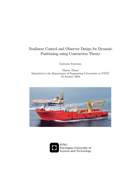
Nonlinear Control and Observer Design for Dynamic ... - NTNU
Nonlinear Control and Observer Design for Dynamic ... - NTNU
Nonlinear Control and Observer Design for Dynamic ... - NTNU

You also want an ePaper? Increase the reach of your titles
YUMPU automatically turns print PDFs into web optimized ePapers that Google loves.
<strong>Nonlinear</strong> <strong>Control</strong> <strong>and</strong> <strong>Observer</strong> <strong>Design</strong> <strong>for</strong> <strong>Dynamic</strong><br />
Positioning using Contraction Theory<br />
Guttorm Torsetnes<br />
Master Thesis<br />
Submitted to the Department of Engineering Cybernetics at <strong>NTNU</strong><br />
22 January 2004
Contents<br />
Abstract<br />
Acknowledgments<br />
Abbreviations<br />
v<br />
vii<br />
ix<br />
1 Introduction 1<br />
1.1 <strong>Dynamic</strong>positioning ....................................... 1<br />
1.2 Motivation ............................................ 1<br />
1.3 Contributions........................................... 3<br />
2 Contraction theory 5<br />
2.1 Abasicconvergenceresult.................................... 5<br />
2.2 Generalizedcontractionanalysis ................................ 7<br />
2.3 Interpretation of contraction <strong>and</strong> stability . . ......................... 8<br />
2.4 Combinationsofcontractingsystems.............................. 10<br />
2.4.1 Parallelcombination................................... 12<br />
2.4.2 Feedbackcombination .................................. 12<br />
2.4.3 Hierarchicalcombination ................................ 12<br />
3 <strong>Observer</strong> design 15<br />
3.1 Acontraction-basedobserverdesign .............................. 15<br />
3.1.1 <strong>Observer</strong>incompact<strong>for</strong>m................................ 16<br />
3.1.2 <strong>Observer</strong>intheframeworkofcontraction ....................... 17<br />
3.1.3 Eliminatingtherotationmatricesfromtheanalysis.................. 18<br />
3.1.4 Contractiontheorem<strong>for</strong>theobserver.......................... 19<br />
3.1.5 <strong>Observer</strong>infeedback<strong>for</strong>m................................ 21<br />
3.1.6 Biasmodel ........................................ 22<br />
3.2 Acontraction-basedobserverdesignwithaccelerationmeasurements............ 23<br />
3.2.1 Simplifiedobserverincompact<strong>for</strong>m .......................... 24<br />
3.2.2 Simplifiedobserverintheframeworkofcontraction.................. 25<br />
3.2.3 Contraction theorem <strong>for</strong> the simplifiedobserver.................... 27<br />
3.3 Gain-scheduled wave filtering .................................. 27<br />
3.3.1 <strong>Observer</strong> model <strong>for</strong> gain-scheduled wave filtering ................... 28<br />
3.3.2 <strong>Observer</strong> with gain-scheduled wave filteringincompact<strong>for</strong>m ............ 29<br />
3.3.3 Stability of LPV systems ................................ 30<br />
3.3.4 Contraction theorem <strong>for</strong> observer with gain-scheduled wave filtering ........ 31<br />
3.3.5 Measuring ω 0 ....................................... 32<br />
3.4 Gain-scheduled wave filteringwithaccelerationmeasurements................ 33<br />
3.4.1 Simplified observer with gain-scheduled wave filteringincompact<strong>for</strong>m....... 33<br />
iii
iv<br />
CONTENTS<br />
3.4.2 Contraction theorem <strong>for</strong> simplified observer with gain-scheduled wave filtering <strong>and</strong><br />
accelerationmeasurements................................ 35<br />
3.5 Concludingremarks ....................................... 36<br />
4 <strong>Control</strong>ler design 37<br />
4.1 Acontractionbasednonlinearseparationprinciple ...................... 37<br />
4.2 <strong>Control</strong>allocation ........................................ 38<br />
4.3 <strong>Observer</strong>-feedbackcontrol .................................... 38<br />
4.3.1 <strong>Observer</strong>-feedback control with gain-scheduled wave filtering ............ 38<br />
4.3.2 <strong>Observer</strong>-feedback control with gain-scheduled wave filtering <strong>and</strong> acceleration feedback............................................<br />
39<br />
5 Simulation results 43<br />
5.1 <strong>Observer</strong>-feedback control with gain-scheduled wave filtering................. 44<br />
5.1.1 Moderateseastate.................................... 44<br />
5.1.2 Veryroughseastate................................... 48<br />
5.2 <strong>Observer</strong>-feedback control with gain-scheduled wave filtering <strong>and</strong> acceleration feedback . . 53<br />
5.2.1 Moderateseastate.................................... 53<br />
5.2.2 Veryroughseastate................................... 56<br />
5.3 Concludingremarks ....................................... 60<br />
6 Conclusion 63<br />
A <strong>Observer</strong> data 65<br />
B <strong>Control</strong>ler data 69
Abstract<br />
This thesis contains new results on the design of dynamic positioning (DP) systems <strong>for</strong> marine surface<br />
vessels.<br />
A positioned ship is continuously exposed to environmental disturbances, <strong>and</strong> the objective of the<br />
DP system is to maintain the desired position <strong>and</strong> heading by the use of thrusters <strong>and</strong> propellers, or<br />
to per<strong>for</strong>m low-speed maneuvering. In a DP system, an observer is needed to produce low-frequency<br />
(LF) estimates of the vessel motion. The observer includes a model of the waves, <strong>and</strong> is there<strong>for</strong>e able<br />
to filter out the wave-frequency (WF) motion from the feedback loop. This is known as wave filtering.<br />
The oscillatory WF motion should not enter the feedback loop because this will only cause unnecessary<br />
wear <strong>and</strong> tear on the actuators. However, the sea state is constantly changing, <strong>and</strong> the observer should<br />
there<strong>for</strong>e be able to automatically adjust the estimation of the LF motion to the slowly-varying wave<br />
model parameters. This can be achieved by measuring the wave model parameters on-line, <strong>and</strong> is referred<br />
to as gain-scheduled wave filtering.<br />
The main contributions of this thesis are:<br />
• <strong>Observer</strong> design: Two observers, with <strong>and</strong> without acceleration measurements, with gain-scheduled<br />
wave filtering, both based on existing observers, have been developed <strong>and</strong> analysed. The gainscheduled<br />
wave filtering is achieved by measuring the slowly-varying wave model parameters online,<br />
<strong>and</strong> there<strong>for</strong>e require no a priori knowledge of the sea state.<br />
• Stability analysis of the resulting observer-controller system by using results on nonlinear cascades:<br />
It is shown that a PID controller (with acceleration feedback when acceleration measurements are<br />
available) can be implemented with the estimates of the proposed observers, <strong>and</strong> that the overall<br />
system is globally contracting, <strong>and</strong> consequently UGES.<br />
The per<strong>for</strong>mance of the DP system is demonstrated in computer simulations <strong>for</strong> different environmental<br />
disturbances.<br />
v
vi<br />
ABSTRACT
Acknowledgments<br />
First <strong>and</strong> <strong>for</strong>emost I would like to thank my supervisor Professor Thor I. Fossen, <strong>and</strong> my advisors, Post<br />
DocJeromeJouffroy <strong>and</strong> PhD student Ivar Ihle, <strong>for</strong> good advice <strong>and</strong> feedback. I am especially grateful<br />
to Jerome Jouffroy <strong>for</strong> teaching me (almost) everything there is to know about contraction theory. Also,<br />
I would like to thank Post Doc Lars Imsl<strong>and</strong> <strong>for</strong> good advice on LMIs, PhD Karl-Petter Lindegaard<br />
<strong>for</strong> feedback regarding his observer design <strong>and</strong> PhD student Øyvind Smogeli <strong>for</strong> helping me to run a<br />
realistic simulation in MCSim. And last, but not least I would like to thank my (<strong>for</strong>mer) fellow students<br />
Johannes Tjønnås, PhD student Morten Breivik <strong>and</strong> PhD student Jostein Hansen <strong>for</strong> countless good<br />
advice during the last five years.<br />
Guttorm Torsetnes<br />
Trondheim, January 2004<br />
vii
viii<br />
ACKNOWLEDGMENTS
Abbreviations<br />
UGAS<br />
UGES<br />
u.n.d.<br />
LF<br />
WF<br />
DOF<br />
AFB<br />
NED<br />
LMI<br />
PDS<br />
PID<br />
LTI<br />
LTV<br />
LPV<br />
Uni<strong>for</strong>mly Globally Asymptotically Stable<br />
Uni<strong>for</strong>mly Globally Exponentially Stable<br />
Uni<strong>for</strong>mly Negative Definite<br />
Low Frequency<br />
Wave Frequency<br />
Degree Of Freedom<br />
Acceleration Feedback<br />
North-East-Down coordinate system<br />
Linear Matrix Inequality<br />
Power Density Spectrum<br />
Proportional Integral Derivative<br />
Linear Time-Invariant<br />
Linear Time-Varying<br />
Linear Parameter-Varying<br />
ix
x<br />
ABBREVIATIONS
Chapter 1<br />
Introduction<br />
1.1 <strong>Dynamic</strong> positioning<br />
The subject of this thesis is the design of DP systems <strong>for</strong> marine surface vessels. DP systems are designed<br />
<strong>for</strong> station-keeping or low speed maneuvering by means of thrusters <strong>and</strong> propellers. In the systems<br />
considered, the pitch <strong>and</strong> roll motion of the vessel is neglected, such that the mathematical model used<br />
<strong>for</strong> control is only a description in 3 DOF as shown in figure 1.1. That is, only the horizontal-plane<br />
position <strong>and</strong> heading is controlled. For background in<strong>for</strong>mation on mathematical modelling of marine<br />
vessels, the reader is referred to (Fossen 2002).<br />
1.2 Motivation<br />
One of the most important issues to take into account when designing DP systems <strong>for</strong> ships, is wave<br />
filtering, <strong>and</strong> dates back to the work of Balchen <strong>and</strong> co-workers. That is, the total vessel motion is<br />
modelled as the superposition of the low-frequency (LF) vessel motion <strong>and</strong> the wave induced wavefrequency<br />
(WF) motion as illustrated in figure 1.2, <strong>and</strong> an observer or a filter is used to reconstruct the<br />
LF motion from noisy position, heading <strong>and</strong> in some cases also velocity <strong>and</strong> acceleration measurements.<br />
In (Grøvlen & Fossen 1996), UGAS of a DP system (simple ship model, observer <strong>and</strong> control law)<br />
was proven by using observer backstepping. A revised version of this paper is found in (Fossen &<br />
Grøvlen 1998). These papers can be regarded as the first attempt to design a fully nonlinear DPcontrol<br />
system, since wave filtering <strong>and</strong> bias estimation was not included. In (Str<strong>and</strong> 1999), an UGES<br />
observer with wave filtering capabilities <strong>and</strong> bias estimation was designed, which resulted in (Fossen<br />
& Str<strong>and</strong> 1999). An extension of this observer with adaptive wave filtering appeared in (Str<strong>and</strong> &<br />
Fossen 1999). This will be commented in detail in chapter 3.3. In (Loria, Fossen & Panteley 2000) the<br />
same observer was used with a PD-type control law, <strong>and</strong> by using the separation principle of (Panteley<br />
& Loria 1998), it was shown that the DP system was UGAS. Recently, in (Lindegaard 2003), this result<br />
has been extended to the case where acceleration measurements are available, <strong>and</strong> it is argued that<br />
the resulting observer-controller system consisting of a PID controller with acceleration feedback, <strong>and</strong> a<br />
UGES observer, is UGAS by using the separation principle of (Panteley & Loria 1998).<br />
However, all these designs assume that the DP system is operating in a static sea state, <strong>and</strong>/or<br />
that the wave model parameters are known a priori. This is of course not a realistic assumption. The<br />
sea state is constantly changing, <strong>and</strong> there<strong>for</strong>e the observer should be able to automatically adjust the<br />
reconstruction of the LF motion in accordance with the varying sea state. To the author’s knowledge,<br />
no observers with gain-scheduled wave filtering that require no a priori knowledge of the sea state exist<br />
in the literature. Thus, the main motivation <strong>for</strong> this thesis has been to design such an observer <strong>for</strong> use<br />
in a DP system <strong>for</strong> marine surface vessels.<br />
1
2 INTRODUCTION<br />
Figure 1.1: Earth-fixed <strong>and</strong> vessel-fixed coordinate frames.<br />
3.5<br />
3<br />
2.5<br />
2<br />
Total motion, LF+WF<br />
1.5<br />
LF motion<br />
1<br />
WF motion<br />
0.5<br />
0<br />
-0.5<br />
1 2 3 4 5 6 7 8 9 10<br />
Time (seconds)<br />
Figure 1.2: The total ship motion as the sum of LF-motion <strong>and</strong> WF-motion
1.3. CONTRIBUTIONS 3<br />
Figure 1.3: DP-system based on position <strong>and</strong> heading measurements y, with gain-scheduled wave filtering<br />
1.3 Contributions<br />
The main contributions of this thesis are<br />
• <strong>Observer</strong> design: Two observers, with <strong>and</strong> without acceleration measurements (chapter 3.3 <strong>and</strong><br />
3.4 respectively), with gain-scheduled wave filtering, both based on existing observers, have been<br />
developed <strong>and</strong> analysed. The gain-scheduled wave filtering is achieved by measuring the slowlyvarying<br />
wave model parameters on-line, <strong>and</strong> there<strong>for</strong>e require no a priori knowledge of the sea<br />
state.<br />
• Stability analysis of the resulting observer-controller system by using results on nonlinear cascades:<br />
It is shown that a PID controller (with acceleration feedback when acceleration measurements are<br />
available) can be implemented with the estimates of the proposed observers, <strong>and</strong> that the overall<br />
system is globally contracting, <strong>and</strong> consequently UGES. The total system is illustrated in figure<br />
1.3<br />
Besides, all the proofs given here, both <strong>for</strong> observer <strong>and</strong> controller design, are done using contraction<br />
theory, which is a new tool to study stability of nonlinear systems, <strong>and</strong> to a small extent has been used in<br />
the design of DP systems. Contraction theory is very powerful, <strong>and</strong> combined with the simplicity of the<br />
design, it will be shown that this is a good alternative to the classical Lyapunov approach. The results<br />
given herein can be regarded as an extension of the work of Lindegaard to include gain-scheduled wave<br />
filtering by using contraction theory, <strong>and</strong> the main results will be summarized in a paper to be submitted<br />
to the IEEE Conference on Decision <strong>and</strong> <strong>Control</strong> (CDC), December 2004 at Atlantis, Paradise Isl<strong>and</strong>,<br />
the Bahamas.
4 INTRODUCTION
Chapter 2<br />
Contraction theory<br />
Contraction theory is a recent tool to study incremental stability of systems of differential equations, <strong>and</strong><br />
was brought to attention in the control engineering community by the work of Slotine <strong>and</strong> Lohmiller.<br />
Incremental stability means stability of trajectories with respect to one another, rather than with respect<br />
to some attractor. For more in<strong>for</strong>mation on the history of contraction theory, the reader is referred to<br />
(Jouffroy 2003a) <strong>and</strong>(Jouffroy 2002, section 2.3).<br />
In this chapter, the main results of contraction theory are summarized. The summary is mainly<br />
based on (Lohmiller & Slotine 1998), to which the reader is referred <strong>for</strong> further details.<br />
2.1 A basic convergence result<br />
The systems considered is of the <strong>for</strong>m<br />
ẋ = f(x, t) (2.1)<br />
where f(x, t) is an n × 1 nonlinear vector function <strong>and</strong> x is the n × 1 state vector. Note that (2.1)<br />
implicitly also represent closed-loop dynamics of systems with state feedback u(x, t). All quantities in<br />
this thesis are assumed to be real <strong>and</strong> smooth, by which is meant that any required derivative or partial<br />
derivativesexistsoriscontinuous.<br />
The system in equation (2.1) can be thought of as an n-dimensional fluid flow, where ẋ is the<br />
n-dimensional "velocity" vector at the n-dimensional position x at time t. Assuming that f(x, t) is<br />
continuously differentiable, equation (2.1) yields the exact differential relation<br />
δẋ= ∂f (x, t)δx, (2.2)<br />
∂x<br />
where δx is the virtual displacement, which is an infinitesimal displacement at a fixed time. Consider<br />
now two neighboring trajectories in the flow field ẋ = f(x, t), <strong>and</strong> the virtual displacement δx between<br />
them. This is illustrated in figure 2.1. The squared distance between these two trajectories can be<br />
defined as δx T δx, leading from (2.2) to the rate of change of length<br />
d<br />
dt (δxT δx) =2δx T δẋ =2δx T ∂f δx (2.3)<br />
∂x<br />
Denote by λ max (x, t) the largest eigenvalue of the symmetric part of the Jacobian ∂f<br />
∂x<br />
(i.e. the largest<br />
eigenvalue of 1 2 ( ∂f<br />
∂x + ∂f<br />
∂x<br />
T<br />
) ), then<br />
5
6 CONTRACTION THEORY<br />
Figure 2.1: Virtual dynamics of two neighboring trajectories<br />
<strong>and</strong> hence,<br />
d<br />
dt (δxT δx) ≤ 2λ max δx T δx (2.4)<br />
kδxk ≤ kδx 0 k e R t<br />
0 λ max(x,t)dt<br />
(2.5)<br />
Assume now that λ max (x, t) is uni<strong>for</strong>mly strictly negative (i.e. ∃ β>0, ∀x, ∀ t ≥ 0, λ max (x, t) ≤<br />
−β 0, ∀x,∀t ≥ 0, 1 ∂f<br />
2 ∂x + ∂f T<br />
≤−βI < 0. (2.6)<br />
∂x<br />
Consider now a ball of constant radius centered about a given trajectory, such that given this trajectory,<br />
the ball remains within a contracting region at all times (i.e.,∀ t ≥ 0). Because any length<br />
within the ball decreases exponentially, any trajectory starting in the ball, remains in the ball (since<br />
by definition the center of the ball is a particular system trajectory) <strong>and</strong> converges exponentially to<br />
the given trajectory. Thus, as in stable linear time-invariant (LTI) systems, the initial conditions are<br />
exponentially "<strong>for</strong>gotten." This leads to the following theorem:<br />
Theorem 2.1 Given the system equations ẋ = f(x, t) any trajectory, which starts in a ball of constant<br />
radius centered about a given trajectory <strong>and</strong> contained at all times in a contraction region, remains in<br />
that ball <strong>and</strong> converges exponentially to this trajectory.<br />
Furthermore, global exponential convergence to the given trajectory is guaranteed if the whole statespace<br />
is a contraction region.
2.2. GENERALIZED CONTRACTION ANALYSIS 7<br />
Figure 2.2: Two trajectories in a contraction region<br />
2.2 Generalized contraction analysis<br />
Theaboveconsiderationscanalsobedoneusingthedifferential coordinate trans<strong>for</strong>mation<br />
δz = Θ(x, t)δx (2.7)<br />
where Θ(x, t) is a square matrix. The time derivative of the local coordinates δz can be written as<br />
d<br />
dt δz = ˙Θδx + Θδẋ (2.8)<br />
= (˙Θ + Θ ∂f<br />
∂x )Θ−1 δz = Fδz (2.9)<br />
where F =(˙Θ + Θ ∂f<br />
∂x )Θ−1 is called the generalized Jacobian. Therateofchangeofsquaredlength<br />
can be written as<br />
d<br />
dt (δzT δz) =2δz T d dt δz =2δzT Fδz (2.10)<br />
Hence, the system ẋ = f(x, t) is in a contraction region if the generalized Jacobian is u.n.d. in that<br />
region. The previous rate of change can also be expressed in δx coordinates, <strong>and</strong> is given by<br />
d<br />
dt (δxT Mδx)=δx T ( ∂f T<br />
M +<br />
∂x Ṁ + M ∂f )δx (2.11)<br />
∂x<br />
where M = Θ T Θ, so that exponential convergence to a single trajectory can be concluded in regions<br />
where<br />
Ã<br />
!<br />
T<br />
∂f<br />
M +<br />
∂x Ṁ + M ∂f ≤−β<br />
∂x<br />
M M (2.12)<br />
where β M > 0. It is immediate to verify that these regions are of course exactly the regions of<br />
uni<strong>for</strong>mly negative definite F in equation (2.9). If M is restricted to be a constant, this exponential<br />
convergence result represents a generalization <strong>and</strong> strengthening of Krasovskii’s generalized asymptotic<br />
global convergence theorem. It may also be regarded as an extension of the Lyapunov matrix equation<br />
in LTI systems due to the term Ṁ.
8 CONTRACTION THEORY<br />
The above leads to the following generalized definition, superseding Definition 2.1 (which corresponds<br />
to Θ = I <strong>and</strong> M = I),<br />
Definition 2.2 Given the system equations ẋ = f(x, t), a region of the state space is called a contraction<br />
region with respect to a uni<strong>for</strong>mly positive definite metric M(x, t) =Θ T Θ, if equivalently F in equation<br />
(2.9) or<br />
T<br />
∂f<br />
M +<br />
∂x Ṁ + M ∂f<br />
∂x<br />
are uni<strong>for</strong>mly negative definite in that region.<br />
(2.13)<br />
<strong>and</strong> the generalized convergence result can be stated as:<br />
Theorem 2.2 Given the system equation ẋ = f(x, t), any trajectory, which starts in a ball of constant<br />
radius with respect to the metric M(x, t), centered at a given trajectory <strong>and</strong> contained at all times in<br />
a contraction region with respect to M(x, t), remains in that ball <strong>and</strong> converges exponentially to this<br />
trajectory.<br />
Furthermore global exponential convergence to the given trajectory is guaranteed if the whole state<br />
space is a contraction region with respect to the metric M(x, t).<br />
It can be shown conversely that the existence of a uni<strong>for</strong>mly positive definite metric with respect<br />
to which the system is contracting is also a necessary condition <strong>for</strong> global exponential convergence of<br />
trajectories. In the linear time-invariant case, a system is globally contracting if <strong>and</strong> only if it is strictly<br />
stable, with F simply being a normal Jordan <strong>for</strong>m of the system <strong>and</strong> Θ the coordinate trans<strong>for</strong>mation<br />
to that <strong>for</strong>m (Lohmiller & Slotine 1998),(Slotine 2003).<br />
2.3 Interpretation of contraction <strong>and</strong> stability<br />
To better underst<strong>and</strong> how stability considerations <strong>for</strong> linear systems can be extended to nonlinear systems<br />
by using virtual displacements as in contraction theory, consider the following autonomous LTI system 1 :<br />
ẋ = Ax, x ∈ R 2 (2.14)<br />
Asufficient condition <strong>for</strong> exponential convergence of the system states to the origin, is that the rate<br />
of change of squared length converges exponentially to zero:<br />
Thus, a sufficient condition is that<br />
d<br />
dt (xT x) = ẋ T x + x T ẋ (2.15)<br />
= x T (A T + A)x (2.16)<br />
A = λ max I
2.3. INTERPRETATION OF CONTRACTION AND STABILITY 9<br />
x T x ≤ x(0) T x(0)e 2λ maxt<br />
(2.18)<br />
<strong>and</strong> consequently<br />
kxk ≤ kx(0)k e λ maxt<br />
(2.19)<br />
which means that x converges exponentially to the origin with the convergence rate determined by<br />
λ max . Evidently, the same result is obtained by using Lyapunov’s direct method with the Lyapunov<br />
function V = x T x. A geometrical interpretation of the above is that<br />
which from elementary calculus can be rewritten as<br />
ẋ T x
10 CONTRACTION THEORY<br />
Thus, if there exists a matrix M = Θ T T<br />
Θ > 0 such that A (t)M(t)+Ṁ(t)+M(t)A(t) < 0, z(<strong>and</strong><br />
consequently x) converges exponentially to the origin.<br />
Finally, consider the nonlinear time-varying system<br />
ẋ = f(x, t) (2.31)<br />
The differential dynamics <strong>for</strong> this system is given by<br />
δẋ = ∂f (x, t)δx (2.32)<br />
∂x<br />
<strong>and</strong> the rate of change of squared length is given by<br />
This means that in the region where<br />
d<br />
dt (δxT δx) = δẋ T δx + δx T δẋ (2.33)<br />
= δx T ( ∂f<br />
∂x<br />
T<br />
T<br />
+ ∂f )δx (2.34)<br />
∂x<br />
∂f<br />
+ ∂f<br />
∂x ∂x < 0 (2.35)<br />
the distance between the trajectories converges exponentially to zeros. Hence, all trajectories in<br />
this region converges to the same trajectory as summarized in theorem 2.1. However, (2.35) is not<br />
a necessary condition <strong>for</strong> exponential incremental stability. Consider the time <strong>and</strong> state-dependent<br />
differential coordinate trans<strong>for</strong>mation<br />
δz = Θ(x, t)δx (2.36)<br />
Therateofchangeofsquaredlengthinδx-coordinates can be written as<br />
d<br />
dt (δxT M(x, t)δx) = δẋ T M(x, t)δx + δx T Ṁ(x, t)δx + δx T M(x, t)δẋ (2.37)<br />
= δx T ∂f<br />
∂x<br />
Ã<br />
= δx T<br />
T<br />
(x, t)M(x, t)δx + δx T<br />
∂f<br />
∂x<br />
Ṁ(x, t)δx + δx T M(x, t) ∂f (x, t)δx (2.38)<br />
∂x<br />
!<br />
T<br />
(x, t)M(x, t)+Ṁ(x, t)+M(x, t)∂f<br />
∂x (x, t) δx (2.39)<br />
Thus, in the region where there exists a metric M = Θ T Θ > 0 such that<br />
T<br />
∂f<br />
M +<br />
∂x Ṁ + M ∂f < 0 (2.40)<br />
∂x<br />
the distance between the trajectories converges exponentially to zeros. If this region is the whole<br />
state-space, then all trajectories in the state-space converge exponentially to the same trajectory, <strong>and</strong><br />
this is called global contraction.<br />
2.4 Combinations of contracting systems<br />
One of the main features of nonlinear contraction, is that it is automatically preserved through a variety of<br />
system combinations. In this section, three combination properties of contracting systems are presented<br />
(Lohmiller & Slotine 1998),(Slotine 2003).<br />
T
2.4. COMBINATIONS OF CONTRACTING SYSTEMS 11<br />
Figure 2.3: Exponential convergence of the system states to the origin with no overshoot<br />
Figure 2.4: Exponential convergence of the system states to the origin with overshoot<br />
Figure 2.5: Exponential convergence of the system states to the origin in z-coordinates
12 CONTRACTION THEORY<br />
2.4.1 Parallel combination<br />
Consider two systems of the same dimension<br />
with virtual dynamics<br />
ẋ 1 = f 1 (x 1 ,t) (2.41)<br />
ẋ 2 = f 2 (x 2 ,t) (2.42)<br />
δż 1 = F 1 δz (2.43)<br />
δż 2 = F 2 δz (2.44)<br />
If both systems are contracting in the same metric, then so is any uni<strong>for</strong>mly positive superposition<br />
α 1 (t)δż 1 + α 2 (t)δż 2 where ∃ α>0, ∀t ≥ 0, α i (t) ≥ α(t) (2.45)<br />
By recursion, this property can be extended to any number of systems.<br />
2.4.2 Feedback combination<br />
Consider two systems, of possibly different dimensions <strong>and</strong> metrics<br />
ẋ 1 = f 1 (x 1 ,x 2 ,t) (2.46)<br />
ẋ 2 = f 2 (x 1 ,x 2 ,t) (2.47)<br />
which are connected in feedback, in such a way that the overall virtual dynamics is of the <strong>for</strong>m<br />
· ¸ · ¸· ¸<br />
d δz1 F1 G δz1<br />
=<br />
dt δz 2 −G T (2.48)<br />
F 2 δz 2<br />
then the augmented system is contracting if the separated plants are contracting. The result can be<br />
extended to any number of systems.<br />
2.4.3 Hierarchical combination<br />
Consider two contracting systems, of possibly different dimensions <strong>and</strong> metrics, connected in series with<br />
virtual dynamics of the <strong>for</strong>m<br />
· ¸ · ¸· ¸<br />
d δz1 F11 0 δz1<br />
=<br />
(2.49)<br />
dt δz 2 F 21 F 22 δz 2<br />
The first equation does not depend on the second, so that exponential convergence of δz 1 to zero<br />
can be concluded <strong>for</strong> uni<strong>for</strong>mly negative definite F 11 . In turn <strong>for</strong> bounded F 21 , F 21 δz 1 represents an<br />
exponentially decaying disturbance in the second equation. Thus, uni<strong>for</strong>m negative definitiveness of F 22<br />
implies exponential convergence of δz 2 to zero. The augmented system is contracting as well, <strong>and</strong> by<br />
recursion, the result extends to hierarchies or cascades of contracting systems of arbitrary depths.<br />
Note that the hierarchical combination (2.49) corresponds to the same kind of combination considered<br />
in the work of Loria <strong>and</strong> Panteley with coworkers, referred to as cascades of nonlinear systems. In<br />
(Panteley & Loria 1998) conditions <strong>for</strong> UGAS <strong>for</strong> systems of the <strong>for</strong>m<br />
ẋ 1 = f 1 (t, x 1 ) (2.50)<br />
ẋ 2 = f 2 (t, x 2 )+g(t, x)x 1 (2.51)
2.4. COMBINATIONS OF CONTRACTING SYSTEMS 13<br />
are given. One necessary condition is that the interconnection term g(t, x) is bounded. Also note<br />
the results established by Sontag on cascades of input-to-state stable (ISS) systems. In (Sontag 1989),<br />
systems of the <strong>for</strong>m<br />
ẋ = f(x)+<br />
mX<br />
u i g(x), ∈ R n (2.52)<br />
i=1<br />
are considered, <strong>and</strong> conditions are given <strong>for</strong> the existence of a smooth map K : R n → R m such that<br />
is GAS.<br />
ẋ = f(x)+G(x)K(x)+G(x)u (2.53)
14 CONTRACTION THEORY
Chapter 3<br />
<strong>Observer</strong> design<br />
This chapter consists of two parts: In the first part, it is shown that the observer of (Fossen & Str<strong>and</strong><br />
1999) <strong>and</strong> the simplified observer of (Lindegaard 2003) are globally contracting (section 3.1 <strong>and</strong> 3.2<br />
respectively). In the second part, a new version of the above mentioned observers with gain-scheduled<br />
wave filtering is presented (section 3.3 <strong>and</strong> 3.4). These observers are particular contributions of this<br />
thesis.<br />
3.1 A contraction-based observer design<br />
In this section, the observer of (Fossen & Str<strong>and</strong> 1999), which is based on position <strong>and</strong> heading measurements<br />
only, is analysed in the framework of contraction theory, <strong>and</strong> it is shown that this observer<br />
is globally contracting with respect to a metric M 1 . First we recapitulate the observer equations. The<br />
model of which the observer is based (neglecting the white noise terms) is given by<br />
˙ξ = A w ξ (3.1)<br />
˙η = R(ψ)ν (3.2)<br />
ḃ = −T −1<br />
b<br />
b (3.3)<br />
M ˙ν + Dν = τ + R T (ψ)b (3.4)<br />
y = η + C w ξ (3.5)<br />
where η =[x, y, ψ] T is the vector of the NED position (x, y) <strong>and</strong> heading (ψ) The yaw angle rotation<br />
matrix is defined as<br />
⎡<br />
⎤<br />
cos(ψ) − sin(ψ) 0<br />
R(y 3 )=R(ψ) = ⎣sin(ψ) cos(ψ) 0⎦ (3.6)<br />
0 0 1<br />
Further, the following assumptions are made (low speed application)<br />
M = M T > 0, Ṁ =0, D > 0 (3.7)<br />
<strong>and</strong> the time bias matrix T b > 0. The first-order WF motion is modelled as a second order linear<br />
system <strong>for</strong> each of the 3 degrees of freedom:<br />
h i (s) = η i<br />
w w<br />
(s) =<br />
k wi s<br />
s 2 +2ζ i ω 0i s + ω 2 0i<br />
(3.8)<br />
15
16 OBSERVER DESIGN<br />
where<br />
ω 0i (i=1,2,3)<br />
ζ i (i=1,2,3)<br />
k wi (i=1,2,3)<br />
dominating wave frequency<br />
relative damping ratio<br />
parameter related to the wave intensity<br />
A minimal state-space realization with x w ∈ R 6 is given by<br />
with<br />
A w =<br />
ẋ w = A w x w + E w w w (3.9)<br />
y = C w x w (3.10)<br />
·<br />
03×3 I 3×3<br />
−Ω 3×3 −Λ 3×3¸<br />
E w =<br />
¸ ·03×1<br />
w w<br />
(3.11)<br />
C w = [0 3×3 ,I 3×3 ] (3.12)<br />
where<br />
Ω<br />
Λ<br />
= diag{ω 2 01,ω 2 02,ω 2 03}<br />
= diag{2ζ 1 ω 01 , 2ζ 2 ω 02 , 2ζ 3 ω 03 }<br />
w w ∈ R 3 = vector of zero-mean Gaussian white noise<br />
The observer is given by:<br />
·<br />
ˆξ = Awˆξ + K1 (y − ŷ) (3.13)<br />
·<br />
ˆη = R(ψ)ˆν + K 2 (y − ŷ) (3.14)<br />
·<br />
ˆb = −T<br />
−1<br />
b<br />
ˆb + K3 (y − ŷ) (3.15)<br />
M ˆν ·<br />
+ Dˆν = τ + R T (ψ)ˆb + R T (ψ)K 4 (y − ŷ) (3.16)<br />
ŷ = ˆη + C wˆξ (3.17)<br />
Note: The observer is based on a priori knowledge of the sea state, which means that the parameters<br />
of A w are assumed to be known. This means that the observer gains can be tuned according to the<br />
peak wave frequency ω 0 to give a notch filter effect which removes 1st order wave components from the<br />
feedback-loop. The reader is referred to (Fossen & Str<strong>and</strong> 1999) <strong>for</strong> the observer tuning rules.<br />
3.1.1 <strong>Observer</strong> in compact <strong>for</strong>m<br />
The observer can be compactly written as<br />
where ˆx =[ˆξ T , ˆη T , ˆb T , ˆν T ] T , y = η + C w ξ <strong>and</strong><br />
·<br />
ˆx = A(ψ)ˆx + Bτ + K y y (3.18)
3.1. A CONTRACTION-BASED OBSERVER DESIGN 17<br />
A(ψ) =<br />
⎡<br />
⎢<br />
⎣<br />
A w − K 1 C w −K 1 0 0<br />
−K 2 C w −K 2 0 R(ψ)<br />
−K 3 C w −K 3 −T −1<br />
b<br />
0<br />
−M −1 R T (ψ)K 4 C w −M −1 R T (ψ)K 4 M −1 R T (ψ) −M −1 D<br />
⎤<br />
⎥<br />
⎦ , (3.19)<br />
B = £ 0 12×3 M −1¤ T<br />
, (3.20)<br />
K y = [K1 T ,K2 T ,K3 T ,K4 T R(ψ)M −1 ] T (3.21)<br />
3.1.2 <strong>Observer</strong> in the framework of contraction<br />
From chapter 2 we conclude that there are generally two ways of verifying that a system of the <strong>for</strong>m<br />
ẋ = f(x, t) is contracting:<br />
1. The Jacobian of the differential dynamics is uni<strong>for</strong>mly negative definite (u.n.d.):<br />
∂f<br />
(x, t) is u.n.d. (3.22)<br />
∂x<br />
2. The Generalized Jacobian of the differential dynamics is u.n.d. This implies that there exists a<br />
positive definite metric M(x, t) =Θ T Θ such that<br />
∂f<br />
∂f<br />
(x, t)M + Ṁ + M (x, t) is u.n.d. (3.23)<br />
∂x ∂x<br />
Note that the first case is a special of the second with M = I. The differential dynamics of (3.18) is<br />
given by<br />
·<br />
δˆx = ∂ ˆf<br />
δˆx = A(ψ)δˆx (3.24)<br />
∂ˆx<br />
Thus, <strong>for</strong> the observer to be contracting with respect to the metric M 1 = I, A(ψ) must be u.n.d.,<br />
that is<br />
A T (ψ)+A(ψ) < 0 (3.25)<br />
When inspecting A(ψ) it is seen from equation (3.11) <strong>and</strong> (3.12) that the upper left element (A w −<br />
K 1 C w ) has zeros in the upper left corner <strong>for</strong> any K 1 , which from Sylvester’s criterion imply that A(ψ)<br />
can only be negative semidefinite. Hence, the above condition is not fulfilled. Thus, we have to look <strong>for</strong><br />
ametricM 1 6= I. We there<strong>for</strong>e introduce the following differential coordinate trans<strong>for</strong>mation<br />
δẑ = Θδˆx (3.26)<br />
where Θ is a constant matrix. This leads to the new differential dynamics<br />
δ ẑ ·<br />
= ΘA(ψ)Θ −1 δẑ (3.27)<br />
hence contraction requires the new Jacobian to be u.n.d.<br />
which can be rewritten as<br />
ΘA(ψ)Θ −1 < 0 (3.28)<br />
A T (ψ)M 1 + M 1 A(ψ) < 0 (3.29)
18 OBSERVER DESIGN<br />
where M 1 = Θ T Θ > 0. From a theoretical point of view, one may say that if equation (3.29) is<br />
fulfilled, then the observer is contracting. However, equation (3.29) is very difficult to solve in practise.<br />
Since A(ψ) includes the rotation matrix R(ψ), the equation must be solved <strong>for</strong> every possible measured<br />
heading ψ. In other words, this result is not suited <strong>for</strong> practical purposes. Since equation (3.29) is<br />
too complex to be solved with st<strong>and</strong>ard software, no conclusion can be made regarding the contraction<br />
properties of the observer.<br />
Evidently, if the rotation matrices (which is the only term making the model nonlinear) could be<br />
disregarded, the contraction condition would be a LMI, <strong>and</strong> thus solved with st<strong>and</strong>ard software.<br />
3.1.3 Eliminating the rotation matrices from the analysis<br />
In this section it is shown that the rotation matrices can be disregarded in the stability analysis by<br />
utilizing the observer error-dynamics-<strong>for</strong>m of (Lindegaard 2003, section 4.4.2 p.53). First we recapitulate<br />
the necessary matrix property from (Lindegaard 2003):<br />
Property 1 A matrix A ∈ R 3 is said to commute with the rotation matrix R(α) if<br />
AR(α) =R(α)A (3.30)<br />
Examples of matrices A satisfying Property 1 are linear combinations A = a 1 R(θ) +a 2 I + a 3 k T k<br />
<strong>for</strong> scalars a i ,θ <strong>and</strong> k =[0, 0, 1] T , the axis of rotation. Also note that since R(α) is orthogonal, that is,<br />
R T (α) =R −1 (α), Property 1 implies that<br />
A = R T (α)AR(α) =R(α)AR T (α) (3.31)<br />
Furthermore, if A is nonsingular, A −1 commutes with R(α) too. That is<br />
AR(α) =R(α)A<br />
A is nonsingular<br />
⇐⇒ A −1 R(α) =R(α)A −1 (3.32)<br />
Thus, given the following assumption<br />
Assumption A1 The bias time constant matrix T b , the observer gains K 2 <strong>and</strong> K 3 <strong>and</strong> each 3 × 3<br />
sub-block of A w , <strong>and</strong> K 1 satisfies Property 1<br />
the observer of (Fossen & Str<strong>and</strong> 1999), can be compactly written as<br />
A =<br />
⎢<br />
⎣<br />
·<br />
ˆx = T T (ψ)AT (ψ)ˆx + Bτ + K y y (3.33)<br />
where ˆx =[ˆξ T , ˆη T , ˆb T , ˆν T ] T , T (ψ) =diag{R T (ψ),R T (ψ),R T (ψ),I 3x3 },y= η + C w ξ <strong>and</strong><br />
⎡<br />
A w − K 1 C w −K 1 0 0<br />
⎤<br />
−K 2 C w −K 2 0 I<br />
−K 3 C w −K 3 −T −1<br />
b<br />
0<br />
−M −1 K 4 C w −M −1 K 4 M −1 −M −1 D<br />
The differential dynamics of the observer can there<strong>for</strong>e be written as<br />
Hence, it is required that J is u.n.d. which corresponds to<br />
⎥<br />
⎦ (3.34)<br />
δ ·<br />
ˆx = T T (ψ)AT (ψ)δˆx = Jδˆx (3.35)<br />
J T + J = T T (ψ)A T T (ψ)+T T (ψ)AT (ψ) < 0 (3.36)
3.1. A CONTRACTION-BASED OBSERVER DESIGN 19<br />
However, since A
20 OBSERVER DESIGN<br />
For the sake of comparison, we will use the same parameters as in (Fossen & Str<strong>and</strong> 1999). That is,<br />
ω 0i =0.8976 rad/s, ζ i =0.1, <strong>and</strong> the cut-off frequency in the notch filter is chosen as ω ci =1.1 rad/s<br />
<strong>and</strong> the ’notch width’ ζ ni =1. By using the tuning rules of (Fossen & Str<strong>and</strong> 1999) this gives values <strong>for</strong><br />
K 1 <strong>and</strong> K 2 . In addition<br />
K 4 = diag{0.1, 0.1, 0.01} (3.45)<br />
K 3 = 0.1K 4 (3.46)<br />
T b = diag{1000, 1000, 1000} (3.47)<br />
This set of parameters gives the system matrix A in equation (??), <strong>and</strong> by using YALMIP (Løfberg<br />
2003) with Matlab TM ,themetricM 1 can be found. The calculations were per<strong>for</strong>med with the SeDuMi<br />
(Sturm 2001) solver, <strong>and</strong> it can be verified in Matlab TM that M 1 is a positive definite, symmetric matrix<br />
M 1 = M1<br />
T > 0 that fulfills equation (3.42). Since M 1 ∈ R 15×15 ,M 1 is not stated due to lack of space,<br />
however it can be mentioned that <strong>for</strong> the given parameters, the resulting calculations gave<br />
max{eig(A T M 1 + M 1 A)} = −1.0396 × 10 −4 (3.48)<br />
min{eig(A T M 1 + M 1 A)} = −1.2649 (3.49)<br />
¯σ(M 1 ) = 4.1771 (maximum singular value) (3.50)<br />
σ(M 1 ) = 0.007195 (minimum singular value) (3.51)<br />
which clearly satisfies the contraction condition. Thus, based on these calculations we conclude that<br />
the observer of (Fossen & Str<strong>and</strong> 1999) is globally contracting <strong>for</strong> the given set of parameters. In order to<br />
visualize that the observer is contracting with respect to a metric M 1 6= I, we can simulate the observer<br />
<strong>for</strong> two different initial conditions, <strong>and</strong> plot the Euclidean norm of the difference of the states:<br />
where<br />
kˆx 1 (t) − ˆx 2 (t)k , ˆx 1 (0) = ˆx 10 , ˆx 2 (0) = ˆx 20 (3.52)<br />
ˆx 1 =ˆx 2 =<br />
h<br />
ˆξT<br />
Figure 3.1 shows the incremental state norm with the initial conditions<br />
ˆη T ˆbT ˆν T i T<br />
(3.53)<br />
ˆx 10 = £ 0 1×3 0 1×3 0 1×3 0 1×3<br />
¤ T<br />
(3.54)<br />
ˆx 20 = £ 0 1×3 0 1×3 0 1×3<br />
£ −1 01×2<br />
¤¤ T<br />
(3.55)<br />
from a simulation in Matlab TM without environmental disturbances. The only difference in the initial<br />
condition is the <strong>for</strong>ward velocity which is estimated to be û 20 = −1 m/s in one observer <strong>and</strong> zero in the<br />
other. The input to the ship model (with initial conditions ˆx 10 ) is a constant <strong>for</strong>ce of 100kN in <strong>for</strong>ward<br />
direction, that is τ =[1× 10 5 , 0, 0] T . The observer gains were chosen as stated above. From figure 3.1<br />
it can be seen that the curve has an overshoot., The reason <strong>for</strong> this is summarized in theorem 2.2 in<br />
(Jouffroy & Lottin 2002):
Incremental state norm<br />
3.1. A CONTRACTION-BASED OBSERVER DESIGN 21<br />
4<br />
3.5<br />
3<br />
2.5<br />
2<br />
1.5<br />
1<br />
0.5<br />
0<br />
0 50 100 150 200 250 300<br />
time [s]<br />
Figure 3.1: Incremental state norm kˆx 1 (t) − ˆx 2 (t)k of the observer with initial conditions ˆx 10 <strong>and</strong> ˆx 20<br />
Theorem 3.2 If the system ẋ = f(x, t) is globally contracting with respect to a constant Θ, then it is<br />
also UGES in the incremental sense, i.e. ∃ k, b > 0 such that ∀t ≥ 0, ∀ x r0 ,x p0 ∈ R n ,<br />
kx r − x p k ≤ k kx r0 − x p0 k e −bt (3.56)<br />
where x r =(x r0 ,t), x p =(x p0 ,t) <strong>and</strong> k•k denotes the Euclidean norm.<br />
Thus, the observer is not contracting with respect to M 1 = I, because this would correspond to a<br />
curve bounded by an exponential which starting point is the norm of the initial value of the difference<br />
kx 1 (0) − x 2 (0)k. The overshoot is bounded by the minimum <strong>and</strong> maximum singular value of M 1 .Also<br />
note that kx 1 (t) − x 2 (t)k is converging quite slowly to zero. This is due to the choice of observer gains.<br />
In this case, the choice of K 2 <strong>and</strong> K 4 will have significant influence on the convergence rate, but both<br />
gains are quite low. The reason <strong>for</strong> this is that K 2 is used to determine the cut-off frequency of the<br />
notch filter ω c >ω 0 , <strong>and</strong> the choice of K 4 is based on the tuning rule (Fossen & Str<strong>and</strong> 1999, section 5)<br />
1/T bi ¿ K 3i /K 4i
22 OBSERVER DESIGN<br />
where F 1 ,F 2 < 0 <strong>for</strong> Ṁ =0. The feedback <strong>for</strong>m is very attractive because the cross-terms are<br />
cancelled, <strong>and</strong> this <strong>for</strong>m is there<strong>for</strong>e used in Backstepping techniques etc. In (Jouffroy & Lottin 2002),<br />
the feedback <strong>for</strong>m was used to show that the observer design in (Fossen & Grøvlen 1998) could be<br />
per<strong>for</strong>med using contraction theory. By per<strong>for</strong>ming the same approach as in (Jouffroy & Lottin 2002)<br />
<strong>for</strong> the observer of (Fossen & Str<strong>and</strong> 1999), the resulting conditions are given by<br />
A T 11M 11 + M 11 A 11 < 0 (3.59)<br />
A T 22 M 22 + M 22 A 22 < 0 (3.60)<br />
M11A T 12 + A T 21M 22 = 0 (3.61)<br />
where M 11 = M11 T > 0, M 22 = M22 T > 0 is to be found <strong>and</strong><br />
A 11 =<br />
A 21 =<br />
¸<br />
·Aw + K 1 C w K 1<br />
·0 0<br />
, A<br />
K 2 C w K 12 =<br />
2¸<br />
0 I<br />
·<br />
¸<br />
−1<br />
K 3 C w K 3<br />
·−T<br />
M −1 K 4 C w M −1 ,A<br />
K 22 =<br />
b<br />
0<br />
4¸<br />
M −1 −M −1 D<br />
(3.62)<br />
(3.63)<br />
That is, if equations (3.59)-(3.61) are fulfilled, the observer (3.13)-(3.17) is contracting with respect<br />
to M 11 <strong>and</strong> M 22 <strong>and</strong> has the feedback <strong>for</strong>m. When comparing the general condition (equation (3.42))<br />
with the conditions <strong>for</strong> the system to have the feedback <strong>for</strong>m (equations (3.59)-(3.61)), it is seen that the<br />
conditions <strong>for</strong> the observer to have the feedback <strong>for</strong>m is much stricter. This can be seen by the equality<br />
constraint (3.61), which means that the equations can no longer be solved as a LMI (the search <strong>for</strong> M 11<br />
<strong>and</strong> M 22 must be per<strong>for</strong>med with semidefinite programming), <strong>and</strong> there<strong>for</strong>e the choice of M 11 <strong>and</strong> M 22<br />
is severely limited as opposed to the case where there are no equality constraint.<br />
Equations (3.59)-(3.61) were calculated with Yalmip (Løfberg 2003) in Matlab TM using the SeDuMi<br />
(Sturm 2001) solver <strong>for</strong> the given set of parameters, however no solution could be found.<br />
3.1.6 Bias model<br />
From a physical point of view, one should use ḃ =0+w w in the model instead of the low-pass filtered<br />
ḃ = −T −1<br />
b<br />
b + w w , which means that the bias is modelled as integration of white noise (r<strong>and</strong>om walk).<br />
When calculating equation (3.42) <strong>for</strong> T b =0with Yalmip (Løfberg 2003) in Matlab TM using the SeDuMi<br />
(Sturm 2001) solver <strong>for</strong> the given set of parameters, the following results were obtained:<br />
max{eig(A T M 1 + M 1 A)} = −2.1948 × 10 −12 (3.64)<br />
min{eig(A T M 1 + M 1 A)} = −0.8622 (3.65)<br />
¯σ(M 1 ) = 3.0373 (maximum singular value) (3.66)<br />
σ(M 1 ) = 0.0054476 (minimum singular value) (3.67)<br />
Hence, the observer is also globally contracting (which from Theorem 3.2 implies UGES) <strong>for</strong> T b =0.<br />
Also note that ¯σ(M 1 ) is less in this case than when using T b = diag{1000, 1000, 1000} as above, which<br />
means that the overshoot as illustrated in figure 3.1 is less.
3.2. A CONTRACTION-BASED OBSERVER DESIGN WITH<br />
ACCELERATION MEASUREMENTS 23<br />
3.2 A contraction-based observer design with acceleration measurements<br />
In this section, the simplified observer of (Lindegaard 2003), which is based on position <strong>and</strong> acceleration<br />
measurements, is analysed in the framework of contraction theory, <strong>and</strong> it is shown that this observer is<br />
globally contracting with respect to a metric M a . The model of which the observer is based, neglecting<br />
the white noise terms <strong>and</strong> without mooring <strong>for</strong>ces (G =0), is given by<br />
ṗ w = A pw p w , ∈ R 6 (3.68)<br />
˙η = R(ψ)ν, ∈ R 3 (3.69)<br />
ḃ = −T −1<br />
b<br />
b, ∈ R 3 (3.70)<br />
˙ν w = A νw ν w , ∈ R nνw (3.71)<br />
ȧ w = A aw a w , ∈ R naw (3.72)<br />
˙ν = −M −1 Dν + M −1 τ + M −1 R T (ψ)b + K a a f , ∈ R 3 (3.73)<br />
ȧ f = −T −1<br />
f<br />
a f , a f (0) = 0 (3.74)<br />
y 1 = η + C pw p w , ∈ R n y1<br />
(3.75)<br />
y 2 = Υ 2 ν + C νw ν w , ∈ R n y2<br />
(3.76)<br />
y 3 = Υ 3 ˙ν + C aw a w , ∈ R n y3<br />
(3.77)<br />
where η =[x, y, ψ] T is the vector of the NED position (x, y) <strong>and</strong> heading (ψ). The yaw angle rotation<br />
matrix is defined as<br />
⎡<br />
⎤<br />
cos(ψ) − sin(ψ) 0<br />
R(y 3 )=R(ψ) = ⎣sin(ψ) cos(ψ) 0⎦ (3.78)<br />
0 0 1<br />
Υ 2 <strong>and</strong> Υ 3 are projections isolating the components of the low frequency (LF) model that are actually<br />
measured.<br />
Remark: Note that equation (3.74) is added to the model as opposed to (Lindegaard 2003). This<br />
means that the model belongs to a bigger class of systems than the model of (Lindegaard 2003), however<br />
<strong>for</strong> the initial condition a f (0) = 0, the models are identical. This relies on the concept of general<br />
systems, which is described in (Jouffroy 2003b). The reason <strong>for</strong> adding equation (3.74) to the model, is<br />
to assure that the observer model is a particular solution of the observer, <strong>and</strong> thus global contraction of<br />
the observer will imply exponential convergence of the estimates to the actual system trajectories.<br />
Also note that the acceleration measurement (equation (3.77)) is a simplification which is only valid<br />
<strong>for</strong> small angular rates (Lindegaard 2003, chapter 4.4, p.52).<br />
Further, the following assumptions are made (low speed application)<br />
M = M T > 0, Ṁ =0, D > 0 (3.79)<br />
The measurements can be written compactly as<br />
⎡<br />
y = ⎣ y ⎤<br />
1<br />
y 2<br />
⎦ = C y (ψ)x + D y τ (3.80)<br />
y 3<br />
where x =[p T w,η T ,b T ,ν T w,a T w,ν T ] <strong>and</strong>
24 OBSERVER DESIGN<br />
⎡<br />
C y (ψ) = ⎣ C ⎤<br />
pw I 0 0 0 0<br />
0 0 0 C νw 0 Υ 2<br />
⎦ (3.81)<br />
0 0 Υ 3 M −1 R T (ψ) 0 C aw −Υ 3 M −1 D<br />
D y = £ ¤<br />
0 0 M −T Υ T T<br />
3<br />
(3.82)<br />
The simplified observer is given by:<br />
˙ˆp w = A pw ˆp w + K 11 (y 1 − ŷ 1 ) (3.83)<br />
·<br />
ˆη = R(ψ)ˆν + K 21 (y 1 − ŷ 1 ) (3.84)<br />
·<br />
ˆb = −T<br />
−1<br />
b<br />
ˆb + K31 (y 1 − ŷ 1 ) (3.85)<br />
·<br />
ˆν w = A νwˆν w + K 42 (y 2 − ŷ 2 ) (3.86)<br />
·<br />
â w = A aw â w + K 53 (y 3 − ŷ 3 ) (3.87)<br />
·<br />
ˆν = −M −1 Dˆν + M −1 τ + M −1 R T (ψ)ˆb +<br />
R T (ψ)K 61 (y 1 − ŷ 1 )+K 62 (y 2 − ŷ 2 )+K a a f (3.88)<br />
ȧ f = −T −1<br />
f<br />
a f + T −1<br />
f<br />
(y 3 − ŷ 3 ) (3.89)<br />
ŷ 1 = ˆη + C pw ˆp w (3.90)<br />
ŷ 2 = Υ 2ˆν + C νwˆν w (3.91)<br />
ŷ 3 = Υ 3ˆ˙ν + C aw â w (3.92)<br />
Note the introduction of a low-pass filter in equation (3.89). The observer is based on a priori<br />
knowledge of the sea state, which means that the parameters of the wave models are assumed to be<br />
known. This means that the observer gains can be tuned according to the peak wave frequency ω 0 to<br />
give a notch filter effect which removes 1st order wave components from the feedback-loop. The reader<br />
is referred to (Lindegaard 2003) <strong>for</strong> the observer tuning rules.<br />
3.2.1 Simplified observer in compact <strong>for</strong>m<br />
Given the following assumption<br />
Assumption A2 The bias time constant matrix T b ,<strong>and</strong>each3 × 3 sub-block of A pw ,K 11 ,K 21 <strong>and</strong><br />
K 31 commutes with the rotation matrix R(ψ) (Property 1).<br />
the observer can be compactly written as<br />
˙ẑ = T T z (ψ)A z T z (ψ)ẑ + B τ τ + K(ψ)y (3.93)<br />
where ẑ =[ˆp T w, ˆη T , ˆb T , ˆν T w, â T w, ˆν T ,a T f ]T ∈ R nz , y as given in equation (3.80) <strong>and</strong><br />
T z (ψ) =diag{R T (ψ),R T (ψ),R T (ψ),R T (ψ),I 6+nνw +n aw<br />
} (3.94)
3.2. A CONTRACTION-BASED OBSERVER DESIGN WITH<br />
ACCELERATION MEASUREMENTS 25<br />
B τ = £ 0 0 0 0 0 M −1 0 ¤ T<br />
⎡<br />
⎤<br />
K 11 0 0<br />
K 21 0 0<br />
K 31 0 0<br />
K(ψ) =<br />
0 K 42 0<br />
⎢<br />
0 0 K 53<br />
⎥<br />
⎣K 61 R(ψ) K 62 0 ⎦<br />
0 0 T −1<br />
f<br />
(3.95)<br />
(3.96)<br />
· ¸<br />
A0 K f<br />
A z =<br />
T −1<br />
f<br />
C 3 −T −1<br />
(3.97)<br />
f<br />
C 3 = £ 0 0 Υ 3 M −1 0 C aw −Υ 3 M −1 D ¤ (3.98)<br />
K f = £ ¤<br />
0 0 0 0 0 Ka<br />
T T<br />
(3.99)<br />
A 0 =<br />
·A11 A 12<br />
A 21 A 22¸<br />
(3.100)<br />
⎡<br />
⎤<br />
A pw − K 11 C pw −K 11 0<br />
A 11 = ⎣ −K 21 C pw −K 21 0 ⎦ (3.101)<br />
−K 31 C pw −K 31 −T −1<br />
b<br />
⎡<br />
A 12 = ⎣ 0 0 0 ⎤<br />
0 0 I⎦ (3.102)<br />
0 0 0<br />
⎡<br />
⎤<br />
0 0 0<br />
A 21 = ⎣ 0 0 −K 53 Υ 3 M −1 ⎦ (3.103)<br />
−K 61 C pw −K 61 M −1<br />
⎡<br />
A 22 = ⎣ A ⎤<br />
νw − K 42 C νw 0 −K 42 Υ 2<br />
0 A aw − K 53 C aw K 53 Υ 3 M −1 D ⎦ (3.104)<br />
−K 62 C νw 0 −M −1 D − K 62 Υ 2<br />
3.2.2 Simplified observer in the framework of contraction<br />
The differential dynamics of (3.93) is given by<br />
δ ˙ẑ = Tz T (ψ)A z T z (ψ)δẑ = Jδẑ (3.105)<br />
Thus, <strong>for</strong> the observer to be contracting with respect to the metric M a = I, J must be u.n.d., that is<br />
J T + J = Tz T (ψ)A T z T z (ψ)+Tz T (ψ)A z T z (ψ) < 0 (3.106)<br />
However, since A z < 0 ⇒ Tz T (ψ)A z T z (ψ) < 0, the above condition is equal to<br />
A T z + A z < 0 (3.107)<br />
When inspecting A z it is seen from equation (3.11) <strong>and</strong> (3.12) (C pw = C w ), that the upper left element<br />
(A w − K 11 C pw ) has zeros in the upper left corner <strong>for</strong> any K 11 , which from Sylvester’s criterion imply
26 OBSERVER DESIGN<br />
that A z canonlybenegativesemidefinite. Hence, the above condition is not fulfilled. Thus, we have to<br />
look <strong>for</strong> a metric M a 6= I. We there<strong>for</strong>e introduce the following differential coordinate trans<strong>for</strong>mation<br />
δˆϑ = Θ a δẑ (3.108)<br />
where Θ a is a constant matrix. This leads to the new differential dynamics<br />
·<br />
δˆϑ = Θ a A z Θ −1<br />
a δˆϑ (3.109)<br />
Contraction requires the new Jacobian to be u.n.d.<br />
which can be rewritten as<br />
where M a = Θ T a Θ a > 0.<br />
Θ a A z Θ −1<br />
a < 0 (3.110)<br />
A T z M a + M a A z < 0 (3.111)<br />
Limitation on the angular rate<br />
The above calculations assume that ˙ψ =0. As noted previously, the acceleration measurements (equation<br />
(3.77)) are a simplification of the real measurements. The low-frequency (LF) linear dynamics that are<br />
being measured is not ˙ν as claimed in (3.77), since ¨η 6= ˙ν when the Earth-fixed frame is considered as<br />
being the inertial frame. More specifically, considering the LF dynamics<br />
y 3,LF =¨η = ˙ψSR(ψ)ν + R(ψ)˙ν (3.112)<br />
where S is a skew symmetric matrix<br />
⎡<br />
S = ⎣ 0 −1 0 ⎤<br />
1 0 0⎦ (3.113)<br />
0 0 0<br />
This means that (3.77) is approximately correct <strong>for</strong> small angular rates (Lindegaard 2003, chapter<br />
4.4, p.52). However, <strong>for</strong> ˙ψ 6= 0, we must ensure that the mapping ˆξ = T z (ψ)ẑ (Lindegaard 2003, chapter<br />
4.4, p.55) is stable. More precisely, we must ensure that this mapping is contracting:<br />
.<br />
·<br />
δˆξ = Tz (ψ)δ ẑ ·<br />
+ T ˙ z (ψ)δẑ (3.114)<br />
= T z (ψ)Tz T (ψ)A z T z (ψ)δẑ + ˙ψS z T z (ψ)δẑ (3.115)<br />
= (A z + ˙ψS z )δˆξ = ∂ ˆf<br />
∂ˆξ δˆξ (3.116)<br />
which is contracting if A z + ˙ψS z is u.n.d.. S z is a skew symmetric matrix which appears when the<br />
rotation T z (ψ) is differentiated:<br />
˙ T z (ψ) = d dt (T z(ψ)) = ˙ψS z T z (ψ) = ˙ψT z (ψ)S z , (3.117)<br />
S z = diag{S T ,S T ,S T ,S T , 0 nz −12} (3.118)<br />
where S is given by (3.113). Thus, we must ensure that ˙ψ is bounded: −r max ≤ ˙ψ ≤ r max .
3.3. GAIN-SCHEDULED WAVE FILTERING 27<br />
3.2.3 Contraction theorem <strong>for</strong> the simplified observer<br />
To verify that the observer estimate ẑ converges to the actual system trajectory z, we compare the<br />
observer model (equation (3.68)-(3.74)) with the observer (equation (3.83)-(3.89)). It is seen that <strong>for</strong><br />
ẑ = z which implies that ŷ = y, the systems are identical. That is, the observer model is a particular<br />
solution of the observer. Thus, from Theorem 2.2 we conclude that if ∂ ˆf is u.n.d (<strong>for</strong> the general case<br />
∂ˆξ<br />
˙ψ 6= 0), all trajectories in the state space converge exponentially to the same trajectory. Hence, ẑ<br />
converges exponentially to z if ∂ ˆf is u.n.d., <strong>and</strong> leads to the following theorem:<br />
∂ˆξ<br />
Theorem 3.3 Contraction of the simplified observer<br />
The simplified observer (3.93) which is based on position <strong>and</strong> acceleration measurements, is globally<br />
contracting <strong>and</strong> the estimation error converges exponentially to zero if, given the assumption A2, <strong>and</strong><br />
<strong>for</strong> an explicitly given maximum angular rate ˙ψ = r max , there exists a metric M a = Ma<br />
T > 0 such that<br />
M a A z + A T z M a < r max (M a S z + Sz T M a ) (3.119)<br />
M a A z + A T z M a < −r max (M a S z + Sz T M a ) (3.120)<br />
where A z is given in equation (3.97) <strong>and</strong> S z in equation.(3.118).<br />
The proof follows directly from the above deduction.<br />
Remark: The LMI in the above theorem is identical to the LMI of theorem 4.2 in (Lindegaard 2003),<br />
<strong>and</strong> merely adds the fact that <strong>for</strong> the given conditions the observer is also globally contracting.<br />
3.3 Gain-scheduled wave filtering<br />
In this section a new design method to automatically adjust the estimation of the LF motion to the<br />
slowly-varying wave model parameters, <strong>for</strong> the observer of (Fossen & Str<strong>and</strong> 1999), is presented. One<br />
possible method is suggested in (Str<strong>and</strong> & Fossen 1999), however this design has two main drawbacks:<br />
Firstly, only the wave model parameters (not the observer gains) are adapted. This means that a priori<br />
knowledge of the sea state is required to choose observer gains, such that a notch filtering effect is<br />
achieved to remove 1st order wave components. Secondly, the observer tuning can be quite difficult.<br />
This is due to the stability analysis which requires one LMI (<strong>for</strong> a given set of observer gains) with two<br />
corresponding equality constraints to be fulfilled. Since there exists no tuning rules to ensure that these<br />
equations are fulfilled, there are two possible ways to tune the observer:<br />
1. Trial <strong>and</strong> error: Choose a set of observer gains, <strong>and</strong> then check if the stability conditions are<br />
fulfilled. However, since there is no evident choice <strong>for</strong> the observer gains, this may take a lot of<br />
time.<br />
2. Solve the stability constraints using an advanced computer algorithm. The constraints have the<br />
<strong>for</strong>m (Str<strong>and</strong> & Fossen 1999, section 4.3)<br />
A T (K)P + PA(K) < 0 (3.121)<br />
B1 T P = C 1 (K) (3.122)<br />
B2 T P = C 2 (3.123)
28 OBSERVER DESIGN<br />
where K is the set of observer gains to be computed, given that there exists a matrix P = P T > 0<br />
such that the above equations are fulfilled. This problem may be solved using computer algorithms<br />
<strong>for</strong> BMIs (bilinear matrix inequalities) with semi-definite constraints. Evidently, the drawback of this<br />
approach is the complexity of the problem. Besides, the computed observer gains will have no physical<br />
meaning.<br />
Due to these problems, a new approach is suggested in which the wave model parameters are measured<br />
on-line. This simplifies the design considerably, because the parameters are not estimated. There<strong>for</strong>e, it is<br />
not necessary to require the system to be persistently exciting (PE) to guarantee parameter convergence.<br />
By doing so, it will be shown that both the wave model parameters <strong>and</strong> the observer gains can be<br />
adjusted on-line to the present sea state. This means that all the properties of the observer of (Fossen<br />
& Str<strong>and</strong> 1999) will be sustained, <strong>and</strong> that no observer tuning is required. The stability proof <strong>for</strong> the<br />
overall system is done with contraction theory using LMIs <strong>and</strong> parameter dependent Lyapunov functions.<br />
3.3.1 <strong>Observer</strong> model <strong>for</strong> gain-scheduled wave filtering<br />
First we state the observer model of (Fossen & Str<strong>and</strong> 1999) when ω 0 isassumedtobeanunknown<br />
parameter. Neglecting the white noise terms, the model is given by<br />
˙ξ = A w (ω 0 )ξ (3.124)<br />
˙η = R(ψ)ν (3.125)<br />
ḃ = −T −1<br />
b<br />
b (3.126)<br />
M ˙ν + Dν = τ + R T (ψ)b (3.127)<br />
y = η + C w ξ (3.128)<br />
And the corresponding observer of (Fossen & Str<strong>and</strong> 1999) where the wave peak frequency ω 0 is<br />
measured on-line is given by<br />
·<br />
ˆξ = Aw (¯ω 0 )ˆξ + K 1 (¯ω 0 )(y − ŷ) (3.129)<br />
·<br />
ˆη = R(ψ)ˆν + K 2 (¯ω 0 )(y − ŷ) (3.130)<br />
·<br />
ˆb = −T<br />
−1<br />
b<br />
ˆb + K3 (y − ŷ) (3.131)<br />
M ˆν ·<br />
+ Dˆν = τ + R T (ψ)ˆb + R T (ψ)K 4 (y − ŷ) (3.132)<br />
ŷ = ˆη + C wˆξ (3.133)<br />
where ¯ω 0 is the measured wave peak frequency, ˆη =[ˆx, ŷ, ˆψ] T is the vector of the NED position (x,y)<br />
<strong>and</strong> heading (ψ) <strong>and</strong><br />
· ¸ 0 I<br />
A w (¯ω 0 )=<br />
(3.134)<br />
−Ω −Λ<br />
where<br />
Ω = diag(¯ω 2 01 , ¯ω2 02 , ¯ω2 03 ) ( measured dominating wave frequency)<br />
Λ = diag(2ζ 1 ¯ω 01 , 2ζ 2 ¯ω 02 , 2ζ 3¯ω 03 )<br />
The design method relies on the following assumptions
3.3. GAIN-SCHEDULED WAVE FILTERING 29<br />
Assumption B1<br />
• ω 0i is the only unknown parameter in the wave model. For st<strong>and</strong>ard wave spectra such as JON-<br />
SWAP, the damping parameter ζ i is approximately constant <strong>for</strong> a wide range of ω 0 . Hence, if the<br />
sea state corresponds to such a wave spectrum, this is a good assumption.<br />
• ˙ω 0i =0(slowly varying)<br />
• ¯ω 0i is calculated from the position measurements using st<strong>and</strong>ard digital signal processing techniques.<br />
Since ω 0i is slowly varying, it will be sufficient to update ¯ω 0i every T minutes (e.q.<br />
T=15). It is assumed that the measured dominating wave frequency ¯ω 0 converges to true value<br />
ω 0 :¯ω 0 → ω 0<br />
• 0 < ¯ω 0min ≤ ¯ω 0 ≤ ¯ω 0max < ∞<br />
3.3.2 <strong>Observer</strong> with gain-scheduled wave filtering in compact <strong>for</strong>m<br />
By per<strong>for</strong>ming the same procedure as in section 3.1.1 <strong>and</strong> 3.1.3, <strong>and</strong> given the following assumption<br />
Assumption A3 The bias time constant matrix T b , the observer gains K 2 (¯ω 0 ) <strong>and</strong> K 3 <strong>and</strong> each<br />
3 × 3 sub-block of A w (ω 0 ),<strong>and</strong> K 1 (¯ω 0 ) commutes with the rotation matrix (Property 1).<br />
the observer in equation (3.129) to (3.133) can be compactly written as<br />
·<br />
ˆx = T T (ψ)A(¯ω 0 )T (ψ)ˆx + Bτ + K y (¯ω 0 )y (3.135)<br />
where ˆx =[ˆξ T , ˆη T , ˆb T , ˆν T ] T , T (ψ) =diag{R T (ψ),R T (ψ),R T (ψ),I 3x3 },y= η + C w ξ <strong>and</strong><br />
A(¯ω 0 ) =<br />
⎡<br />
⎤<br />
A w (¯ω 0 ) − K 1 (¯ω 0 )C w −K 1 (¯ω 0 ) 0 0<br />
⎢ −K 2 (¯ω 0 )C w −K 2 (¯ω 0 ) 0 I<br />
⎥<br />
⎣ −K 3 C w −K 3 −T −1<br />
b<br />
0 ⎦ (3.136)<br />
−M −1 K 4 C w −M −1 K 4 M −1 −M −1 D<br />
K y (¯ω 0 ) = [K T 1 (¯ω 0 ),K T 2 (¯ω 0 ),K T 3 ,K T 4 R(ψ)M −1 ] T (3.137)<br />
The differential dynamics of the observer can there<strong>for</strong>e be written as<br />
δ ˆx ·<br />
= T T (ψ)A(¯ω 0 )T (ψ)δˆx = J(¯ω 0 )δˆx (3.138)<br />
Hence, it is required that J(¯ω 0 ) is u.n.d. which corresponds to<br />
J T (¯ω 0 )+J(¯ω 0 )=T T (ψ)A T (¯ω 0 )T (ψ)+T T (ψ)A(¯ω 0 )T (ψ) < 0 (3.139)<br />
However, since A(¯ω 0 ) < 0 ⇒ T T (ψ)A T (¯ω 0 )T (ψ) < 0 the above condition is equal to<br />
A T (¯ω 0 )+A(¯ω 0 ) < 0 (3.140)<br />
That is, the rotation matrices can be removed from the analysis. Instead of (3.138) we there<strong>for</strong>e<br />
consider the linear system<br />
δ ˆx ·<br />
= A(¯ω 0 )δˆx (3.141)<br />
Hence, it must be proven that A(¯ω 0 ) fulfills property (3.140) <strong>for</strong> 0 ≤ ¯ω 0min < ¯ω 0 ≤ ¯ω 0max < ∞.
30 OBSERVER DESIGN<br />
3.3.3 Stability of LPV systems<br />
Linear parameter dependent (LPV) systems are linear systems where the system matrices depend on<br />
an unknown parameter, <strong>and</strong> affine LPV systems are linear systems where the system matrices depend<br />
affinely on the unknown parameter By considering ¯w 0 <strong>and</strong> ¯w 0 2 as two different parameters which are<br />
measured, the differential dynamics (3.141) can be rewritten as an autonomous, affine LPV system. We<br />
there<strong>for</strong>e need to use some tools <strong>for</strong> LPV systems. Consider the linear system defined by<br />
ẋ = A(δ)x (3.142)<br />
where the state matrix A(δ) is a function of a real valued parameter vector δ =col(δ 1 ,δ 2 , ..., δ k )<br />
∈ R k . A sufficient condition <strong>for</strong> x ∗ =0to be an asymptotically stable equilibrium point of (3.142) is the<br />
existence of a quadratic Lyapunov function<br />
with K = K T > 0 such that<br />
V (x) =x T Kx (3.143)<br />
dV (x, t)<br />
˙V = < 0 (3.144)<br />
dt<br />
along all trajectories of x of (3.142) that originate in a neighborhood of the equilibrium x ∗ =0.<br />
Definition 3.1 The system (3.142) is said to be quadratically stable <strong>for</strong> perturbations ∆ if there<br />
exists a matrix K = K T such that<br />
A(δ(t)) T K + KA(δ(t)) < 0 (3.145)<br />
<strong>for</strong> all perturbations δ ∈ ∆ (Weil<strong>and</strong> & Scherer 2000).<br />
The function ’quadstab’ inMatlab TM canbeusedtofind a parameter dependent Lyapunov function<br />
which fulfills Definition 3.1. The main disadvantage in searching <strong>for</strong> one quadratic Lyapunov function<br />
<strong>for</strong> a class of parameter dependent systems is the conservatism of the test to prove stability of a class<br />
of models. Indeed, the test of quadratic stability does not discriminate between systems that have slow<br />
time-varying parameters <strong>and</strong> systems whose dynamical characteristics quickly vary in time. To reduce<br />
conservatism of the quadratic stability test, parameter dependent Lyapunov functions will be considered<br />
instead.<br />
Definition 3.2 The system (3.142) is called affinely quadratically stable if there exists matrices<br />
K 0 = K0 T , ...., K k = Kk<br />
T such that<br />
K(δ) =K T (δ) :=K 0 + δ 1 K 1 + ... + δ k K k > 0 (3.146)<br />
<strong>for</strong> all perturbations δ ∈ ∆.<br />
A(δ) T K(δ)+K(δ)A(δ)+ dK(δ)<br />
dt<br />
< 0 (3.147)<br />
Definition 3.2 is a modification of the definition of affine quadratic stability used in (Weil<strong>and</strong> &<br />
Scherer 2000), since it is required that K(δ) is symmetric. In Matlab TM , the function ’pdlstab’ is<br />
designed to find parameter dependent Lyapunov functions of the <strong>for</strong>m given in Definition 3.2.
3.3. GAIN-SCHEDULED WAVE FILTERING 31<br />
3.3.4 Contraction theorem <strong>for</strong> observer with gain-scheduled wave filtering<br />
In our case equation (3.147) reduces to A(δ) T K(δ)+K(δ)A(δ) < 0, since the parameters are assumed to<br />
be time-invariant (slowly varying). Thus, if this requirement is fulfilled, the proposed observer structure<br />
will be contracting.<br />
Now it must be ensured that the observer estimate ˆx converges to the actual system trajectory x. By<br />
comparing the observer model (equation (3.124)-(3.128)) with the observer (equation (3.129)-(3.133)),<br />
it is seen that <strong>for</strong> ˆx = x which implies that ŷ = y, the systems are identical. That is, the observer model<br />
is a particular solution of the observer. From Theorem 2.2, we there<strong>for</strong>e conclude that if ∂ ˆf<br />
∂ ˆx<br />
is u.n.d,<br />
all trajectories in the state space converge exponentially to the same trajectory. Hence, ˆx converges<br />
exponentially to x if ∂ ˆf<br />
∂ ˆx<br />
is u.n.d This leads to the following theorem:<br />
Theorem 3.4 Contracting observer with gain-scheduled wave filtering based on position<br />
<strong>and</strong> heading measurements The observer in equation (3.129)-(3.133) is globally contracting <strong>and</strong> the<br />
observer error converges exponentially to zero if there exists a metric M(¯ω 0 )=M T (¯ω 0 ) > 0 such that<br />
A(¯ω 0 ) T M(¯ω 0 )+M(¯ω 0 )A(¯ω 0 ) < 0 (3.148)<br />
given the assumptions B1 <strong>and</strong> A3, <strong>and</strong>whereA(¯ω 0 ) is given in (3.136).<br />
The proof follows directly from the above deduction.<br />
Note that the M(¯ω 0 ) corresponds to a parameter dependent metric used in contraction theory. To<br />
verify that Theorem 3.4 can be fulfilled, we rewrite A(¯ω 0 ) as<br />
where<br />
A(¯ω 0 )=A 0 + A 1¯ω 0 + A 2 ¯ω 2 0 (3.149)<br />
A 0 =<br />
A 011 =<br />
A 012 =<br />
⎡<br />
⎤<br />
A 011 A 012 0 6×3 0 6×3<br />
⎢ 0 3×6 0 3×3 0 3×3 I 3×3<br />
⎥<br />
⎣ −K 3 −K 3 −T −1<br />
b<br />
0 3×3<br />
⎦ (3.150)<br />
−M −1 K 4 C w −M −1 K 4 M −1 −M −1 D<br />
¸<br />
·03×3 (1 + 2(ζ d − ζ)k)I 3×3<br />
(3.151)<br />
0 3×3 0 3×3<br />
¸<br />
·2(ζd − ζ)kI 3×3<br />
(3.152)<br />
0 3×3<br />
A 1 =<br />
A 111 =<br />
A 112 =<br />
⎡<br />
⎤<br />
A 111 A 112 0 6×3 0 6×3<br />
⎢−kI 3×3 C w −kI 3×3 0 3×3 0 3×3<br />
⎥<br />
⎣ 0 3×6 0 3×3 0 3×3 0 3×3<br />
⎦ (3.153)<br />
0 3×6 0 3×3 0 3×3 0 3×3<br />
·03×3 0 3×3<br />
(3.154)<br />
0 3×3 −2ζ d I 3×3¸<br />
·<br />
0 3×3<br />
(3.155)<br />
−2(ζ d − ζ)I 3×3¸
32 OBSERVER DESIGN<br />
A 2 =<br />
A 211 =<br />
⎡<br />
⎤<br />
A 211 0 6×3 0 6×3 0 6×3<br />
⎢0 3×6 0 3×3 0 3×3 0 3×3<br />
⎥<br />
⎣0 3×6 0 3×3 0 3×3 0 3×3<br />
⎦ (3.156)<br />
0 3×6 0 3×3 0 3×3 0 3×3<br />
·03×3 0 (3.157)<br />
−I 0 3×3¸<br />
where ζ d is the desired damping ratio (typically 1) <strong>and</strong> ω c = kω 0 ,k>1, is the cut-off frequency<br />
of the notch filter. By using the LMI Toolbox in Matlab TM (see ’pdlstab’), a parameter dependent<br />
Lyapunov function<br />
M(¯ω 0 )=M 0 + M 1 ¯ω 0 + M 2¯ω 2 0 (3.158)<br />
which satisfies equation (3.149) can be found. Since M 0 ,M 1 ,M 2 ∈ R 15×15 the matrices are not<br />
stated due to lack of space. Calculations show that the conditions are easily satisfied <strong>for</strong> the bounds:<br />
¯ω 0min =0.01 rad/s <strong>and</strong> ¯ω 0max = 100 rad/s , which practically cover every possible sea state, <strong>for</strong> the<br />
choice of T b ,K 3 <strong>and</strong> K 4 stated in (Fossen & Str<strong>and</strong> 1999) with ω c =1.22ω 0 <strong>and</strong> ζ d =1<strong>for</strong> the same<br />
supply vessel which is also found in (Matlab GNC Toolbox 2003).<br />
In other words, this means that all the vital properties of the observer which are<br />
• wave filtering capabilities: The observer estimates the wave frequency components η WF<br />
these frequencies can be removed from the feedback loop<br />
so that<br />
• notch filtering: The choice of K 1 <strong>and</strong> K 2 (see Fossen & Str<strong>and</strong> 1999) are done such that the 1st<br />
order wave components (frequencies around the dominating wave frequency ω 0 )arenotchfiltered.<br />
• exponential converges to zero of the estimation error<br />
• velocity <strong>and</strong> bias estimation<br />
remain intact as the observer adapts to the changing sea state, <strong>and</strong> there is no need <strong>for</strong> observer<br />
tuning (K 3 <strong>and</strong> K 4 are simply chosen so that 1/T bi ¿ K 3i /K 4i
3.4. GAIN-SCHEDULED WAVE FILTERING WITH ACCELERATION<br />
MEASUREMENTS 33<br />
1. High-pass filter the position <strong>and</strong> heading measurements to remove the vessel drift<br />
2. Sample <strong>and</strong> buffer a time series of the position <strong>and</strong> heading measurements<br />
3. Calculate the PDS <strong>and</strong> identify the peak frequency<br />
4. Use a rate limiter to assure that the assumption ˙ω 0 =0is maintained<br />
In the observer the same ¯ω 0 is used in all degrees of freedom. Also, the median of the estimated peak<br />
frequencies should be used in case of loss of position measurements. Figure 3.2 shows how this can be done<br />
in Simulink TM in one degree of freedom. The blocks are found in the DSP (Digital Signal Processing)<br />
Toolbox in Simulink TM . The power spectrum estimation method used here is the parametric method<br />
of Burg, which has several advantages compared to nonparametric methods. Parametric methods is<br />
recommended since they give better estimates <strong>for</strong> shorter finite-length data records. For more in<strong>for</strong>mation<br />
on the Burg method <strong>and</strong> digital signal processing, the reader is referred to (Proakis & Manolakis 1996).<br />
Figure 3.2: Measurement of ω 0 inonedegreeoffreedom<br />
3.4 Gain-scheduled wave filtering with acceleration measurements<br />
In this section, the result of section 3.3 is extended to the simplified observer of (Lindegaard 2003). Since<br />
the observer of (Fossen & Str<strong>and</strong> 1999) <strong>and</strong> the simplified observer of (Lindegaard 2003) have the same<br />
<strong>for</strong>m, the procedure is identical.<br />
3.4.1 Simplified observer with gain-scheduled wave filtering in compact <strong>for</strong>m<br />
The observer model is given by
34 OBSERVER DESIGN<br />
ṗ w = A pw (¯ω 0 )p w , ∈ R 6 (3.159)<br />
˙η = R(ψ)ν, ∈ R 3 (3.160)<br />
ḃ = −T −1<br />
b<br />
b, ∈ R 3 (3.161)<br />
˙ν w = A νw (¯ω 0 )ν w , ∈ R n νw<br />
(3.162)<br />
ȧ w = A aw (¯ω 0 )a w , ∈ R n aw<br />
(3.163)<br />
˙ν = −M −1 Dν + M −1 τ + M −1 R T (ψ)b + K a a f , ∈ R 3 (3.164)<br />
ȧ f = −T −1<br />
f<br />
(¯ω 0 )a f , a f (0) = 0 (3.165)<br />
y 1 = η + C pw p w , ∈ R n y1<br />
(3.166)<br />
y 2 = Υ 2 ν + C νw ν w , ∈ R n y2<br />
(3.167)<br />
y 3 = Υ 3 ˙ν + C aw a w , ∈ R n y3<br />
(3.168)<br />
<strong>and</strong> given the following assumption<br />
Assumption B4 The bias time constant matrix T b ,<strong>and</strong>each3×3 sub-block of A pw (¯ω 0 ),K 11 (¯ω 0 ),K 21 (¯ω 0 )<br />
<strong>and</strong> K 31 commutes with the rotation matrix R(ψ)<br />
the observer can be written compactly as<br />
·<br />
ẑ = T T z (ψ)A z (¯ω 0 )T z (ψ)ẑ + B τ τ + K(ψ, ¯ω 0 )y (3.169)<br />
where ẑ =[ˆp T w, ˆη T , ˆb T , ˆν T w, â T w, ˆν T ,a T f ]T ∈ R nz , y as given in equation (3.80) <strong>and</strong><br />
T z (ψ) =diag{R T (ψ),R T (ψ),R T (ψ),R T (ψ),I 6+nνw+n aw<br />
} (3.170)<br />
B τ = £ 0 0 0 0 0 M −1 0 ¤ T<br />
⎡<br />
⎤<br />
K 11 (¯ω 0 ) 0 0<br />
K 21 (¯ω 0 ) 0 0<br />
K 31 0 0<br />
K(ψ, ¯ω 0 ) =<br />
0 K 42 (¯ω 0 ) 0<br />
⎢<br />
0 0 K 53<br />
⎥<br />
⎣K 61 R(ψ) K 62 (¯ω 0 ) 0 ⎦<br />
0 0 T −1<br />
f<br />
(¯ω 0 )<br />
(3.171)<br />
(3.172)<br />
· ¸<br />
A0 (¯ω 0 ) K f<br />
A z (¯ω 0 ) =<br />
T −1<br />
f<br />
(¯ω 0 )C 3 −T −1<br />
(3.173)<br />
f<br />
(¯ω 0 )<br />
C 3 = £ 0 0 Υ 3 M −1 0 C aw −Υ 3 M −1 D ¤ (3.174)<br />
K f = £ ¤<br />
0 0 0 0 0 Ka<br />
T T<br />
(3.175)<br />
¸<br />
·A11 (¯ω<br />
A 0 (¯ω 0 )= 0 ) A 12<br />
A 21 A 22 (¯ω 0 )<br />
(3.176)<br />
⎡<br />
A pw (¯ω 0 ) − K 11 (¯ω 0 )C pw −K 11 (¯ω 0 ) 0<br />
⎤<br />
A 11 (¯ω 0 )= ⎣ −K 21 (¯ω 0 )C pw −K 21 (¯ω 0 ) 0 ⎦ (3.177)<br />
−K 31 C pw −K 31 −T −1<br />
b
3.4. GAIN-SCHEDULED WAVE FILTERING WITH ACCELERATION<br />
MEASUREMENTS 35<br />
⎡<br />
A 12 = ⎣ 0 0 0 ⎤<br />
0 0 I⎦ (3.178)<br />
0 0 0<br />
⎡<br />
⎤<br />
0 0 0<br />
A 21 = ⎣ 0 0 −K 53 Υ 3 M −1 ⎦ (3.179)<br />
−K 61 C pw −K 61 M −1<br />
⎡<br />
A 22 (¯ω 0 )= ⎣ A ⎤<br />
νw(¯ω 0 ) − K 42 (¯ω 0 )C νw 0 −K 42 (¯ω 0 )Υ 2<br />
0 A aw (¯ω 0 ) − K 53 C aw K 53 Υ 3 M −1 D ⎦ (3.180)<br />
−K 62 (¯ω 0 )C νw 0 −M −1 D − K 62 (¯ω 0 )Υ 2<br />
3.4.2 Contraction theorem <strong>for</strong> simplified observer with gain-scheduled wave<br />
filtering <strong>and</strong> acceleration measurements<br />
Theorem 3.5 Contracting observer with gain-scheduled wave filtering based on position,<br />
heading <strong>and</strong> acceleration measurements. The observer in equation (3.169) is globally contracting<br />
<strong>and</strong> the estimation error converges exponentially to zero if, given the assumptions B1 <strong>and</strong> B4, <strong>and</strong><strong>for</strong><br />
an explicitly given maximum angular rate ˙ψ = r max , there exists a metric M a (¯ω 0 )=Ma T (¯ω 0 ) > 0 such<br />
that<br />
M a (¯ω 0 )A z (¯ω 0 )+A T z (¯ω 0 )M a (¯ω 0 ) 0 such that the generalized Jacobian is<br />
u.n.d.:<br />
∂ ˆf(¯ω<br />
T<br />
0 )<br />
M(¯ω 0 )+M(¯ω 0 ) ∂ ˆf(¯ω 0 )<br />
< 0<br />
∂ˆξ<br />
∂ˆξ<br />
∀ˆξ,∀t ≥ 0 (3.186)<br />
Inserting ˙ψ = ±r max this corresponds to the two equations
36 OBSERVER DESIGN<br />
which can be rewritten as<br />
M(¯ω 0 )(A z (¯ω 0 )+r max S z )+(A z (¯ω 0 )+r max S z ) T M(¯ω 0 ) < 0 (3.187)<br />
M(¯ω 0 )(A z (¯ω 0 ) − r max S z )+(A z (¯ω 0 ) − r max S z ) T M(¯ω 0 ) < 0 (3.188)<br />
M(¯ω 0 )A z (¯ω 0 )+A T z (¯ω 0 )M(¯ω 0 ) < −r max (M(¯ω 0 )S z + Sz T M(¯ω 0 )) (3.189)<br />
M(¯ω 0 )A z (¯ω 0 )+A T z (¯ω 0 )M(¯ω 0 )
Chapter 4<br />
<strong>Control</strong>ler design<br />
In order to take advantage of the observers from the previous chapter, the control law must be implemented<br />
using the estimated states instead of the true one, due to the absence of required measurements,<br />
<strong>and</strong> because of the wave filtering. Hence, it must be shown that such a combination yields stability of<br />
the closed loop.<br />
In (Panteley & Loria 1998), a separation principle <strong>for</strong> nonlinear time-varying systems in cascades<br />
was established, <strong>and</strong> in (Loria et al. 2000), this separation principle was used to prove UGAS of the<br />
closed loop <strong>for</strong> a PD-controller with bias feed-<strong>for</strong>ward using the observer of (Fossen & Str<strong>and</strong> 1999).<br />
This separation principle is also referred to in (Lindegaard 2003), to argue that a PID controller with<br />
acceleration feedback can be implemented using the estimates from the observer in section 3.2.<br />
Likewise, the observers with gain-scheduled wave filtering from section 3.3 <strong>and</strong> 3.4 can be used with<br />
the corresponding controllers as their static wave filtering counterparts, using the separation principle of<br />
(Panteley & Loria 1998) or (Loria & Morales 2002), since the observers with gain-scheduled wave filtering<br />
are UGES. However, in contraction theory there exists a simpler <strong>and</strong> more powerful separation principle,<br />
which is used in this chapter to prove UGES of the closed loop when the controller is implemented using<br />
the state estimates.<br />
4.1 A contraction based nonlinear separation principle<br />
The following separation principle is cited from (Lohmiller & Slotine March 2000): Consider a plant<br />
dynamics in terms of an explicit state vector z<br />
combined with the observer<br />
ż = f(z, t)+G(z, t)u(ẑ,t) (4.1)<br />
·<br />
ẑ = f(ẑ, t) − [e(ẑ) − e(z)] + G(z, t)u(ẑ,t) (4.2)<br />
where ẑ is the state estimate, <strong>and</strong> u(ẑ,t) is the control input. Letting ˜z =ẑ − z, the Lyapunov-like<br />
analysis<br />
Z<br />
d<br />
∂(f − e)<br />
dt (˜zT ˜z) =2˜z T (z − λ˜z)dλ˜z (4.3)<br />
∂z<br />
then shows that the convergence rate of ẑ to z is specified by ∂(f −e)/∂z. For bounded G, this system<br />
is a hierarchy, <strong>and</strong> thus the convergence rate of the plant dynamics is given by ∂(f +Gu)/∂z. This result<br />
may be viewed as an extension of the st<strong>and</strong>ard linear separation principle in Luenberger (1979).<br />
37
38 CONTROLLER DESIGN<br />
Figure 4.1: Block diagram showing the control allocation block in a feedback control system<br />
4.2 <strong>Control</strong> allocation<br />
In this thesis algorithms <strong>for</strong> control allocation is not considered. In all the equations given here, the<br />
control <strong>for</strong>ces <strong>and</strong> moments are collected in the generalized control <strong>for</strong>ce vector τ. However, <strong>for</strong> implementation,<br />
the generalized <strong>for</strong>ces must be allocated to the actuators of the ship with an appropriate<br />
algorithm. For more in<strong>for</strong>mation on control allocation, the reader is referred to the work of Tor. A.<br />
Johansen (Johansen 2003), <strong>and</strong> (Fossen 2002) <strong>and</strong> references therein.<br />
Let C A (z, t) represent the control allocation algorithm. See figure 4.1. When comparing equation<br />
(4.2) with the observers from chapter 3, it is seen that the function G(z,t) is given by.<br />
G(z, t) =M −1 C −1<br />
A u (4.4)<br />
Hence, <strong>for</strong> any appropriate control allocation algorithm C A (z,t), G(z,t) will be bounded, <strong>and</strong> consequently<br />
the observer-feedback control structure described by (4.1) <strong>and</strong> (4.2) is a hierarchy.<br />
4.3 <strong>Observer</strong>-feedback control<br />
In this section, it is shown that a PID-controller implemented with the state estimates from the observer<br />
with gain-scheduled wave filtering in section 3.3, <strong>and</strong> that a PID-controller with acceleration feedback<br />
implemented with the state estimates from the observer with gain-scheduled wave filtering in section<br />
3.4, yield an overall globally contracting (<strong>and</strong> consequently UGES) DP system.<br />
Note that the observers from section 3.1 <strong>and</strong> 3.2 are particular solutions of their gain-scheduled<br />
counterparts, <strong>and</strong> there<strong>for</strong>e the theorems given here are also valid <strong>for</strong> the observers with static wave<br />
filtering. In the static case, simply disregard that ω 0 is a slowly varying parameter, <strong>and</strong> modify the<br />
theorems thereafter.<br />
For convenience, let us restate the ship model of which the controller design is based:<br />
˙η = R(ψ)ν (4.5)<br />
M ˙ν + Dν = τ (4.6)<br />
4.3.1 <strong>Observer</strong>-feedback control with gain-scheduled wave filtering<br />
Consider the following control law:<br />
˙ξ = η (4.7)<br />
˙ξ d = η d (4.8)<br />
τ = −K i R T (ψ)(ξ − ξ d ) − K d ν − K p R T (ψ)(η − η d ) (4.9)
4.3. OBSERVER-FEEDBACK CONTROL 39<br />
where η d (t) is the desired position <strong>and</strong> heading. Thus, if<br />
⎡ ⎤<br />
˙ξ<br />
⎣ ˙η ⎦ =<br />
˙ν<br />
⎡<br />
⎤ ⎡<br />
0 3×3 I 3×3 0 3×3<br />
⎣ 0 3×3 0 3×3 R(ψ) ⎦ ⎣ ξ ⎤<br />
η⎦ + τ d (4.10)<br />
−M −1 K i R T (ψ) −M −1 K p R T (ψ) −M −1 (D + K d ) ν<br />
τ d = £ 0 0 (R T (K i z d + K p η d )) T ¤ T<br />
which can be compactly written as<br />
where x =[ξ T ,η T ,ν T ] T <strong>and</strong><br />
(4.11)<br />
ẋ = T T (ψ)A τ T (ψ)x + τ d (4.12)<br />
T (ψ) =diag{R T (ψ),R T (ψ),I 3×3 } (4.13)<br />
⎡<br />
A τ = ⎣ 0 ⎤<br />
3×3 I 3×3 0 3×3<br />
0 3×3 0 3×3 I 3×3<br />
⎦ (4.14)<br />
−M −1 K i −M −1 K p −M −1 (D + K d )<br />
is contracting, the hierarchy of the PID controller implemented with the state estimates<br />
˙ˆξ = ˆη (4.15)<br />
˙ξ d = η d (4.16)<br />
τ = −K i R T (ψ)(ˆξ − ξ d ) − K dˆν − K p R T (ψ)(ˆη − η d ) (4.17)<br />
from the observer (3.135), will be contracting.<br />
Theorem 4.1 <strong>Observer</strong>-feedback control with gain-scheduled wave filtering based on position<br />
<strong>and</strong> heading measurements. The hierarchy of the observer (3.135) with gain-scheduled wave filtering<br />
<strong>and</strong> the PID controller (4.17) is globally contracting if there exists a metric M(¯ω 0 )=M T (¯ω 0 ) > 0 such<br />
that<br />
A(¯ω 0 ) T M(¯ω 0 )+M(¯ω 0 )A(¯ω 0 ) < 0 (4.18)<br />
<strong>and</strong> a metric M τ = M T τ<br />
> 0 such that<br />
A T τ M τ + M τ A τ < 0 (4.19)<br />
given the assumptions B1 <strong>and</strong> A3, <strong>and</strong>whereA(¯ω 0 ) is given in (3.136) <strong>and</strong> A τ is given in (4.14).<br />
The proof follows directly from the separation principle.<br />
4.3.2 <strong>Observer</strong>-feedback control with gain-scheduled wave filtering <strong>and</strong> acceleration<br />
feedback<br />
Suppose that y a ∈ R ny3 is the measured accelerations in the body-frame <strong>and</strong> that Π ∈ R ny3×3 is<br />
the projection extracting the available acceleration measurements y a = Π ˙ν. Let the control law be<br />
(Lindegaard 2003, chapter 5.4, p.75)
40 CONTROLLER DESIGN<br />
ȧ f_τ = A f a f_τ + B f (y a − Π{(r − r d )S T R T (ψ − ψ d )ν d + R T (ψ − ψ d )˙ν d }) ∈ R n y3<br />
(4.20)<br />
τ = τ PID − K a a f_τ (4.21)<br />
where a f_τ is the filtered acceleration error <strong>and</strong> τ PID is to be determined shortly. At low frequencies<br />
a f_τ ≈ y a − Π{(r − r d )S T R T (ψ − ψ d )ν d + R T (ψ − ψ d )˙ν d } (4.22)<br />
which means that the acceleration term K a a f_τ can be regarded as a change in the system’s mass.<br />
This can be seen by inserting (4.21) with (4.22) into the ship model, which results in<br />
˙η = R(ψ)ν (4.23)<br />
(M + K a Π)˙ν + Dν = τ PID − K a Π{(r − r d )S T R T (ψ − ψ d )ν d + R T (ψ − ψ d )˙ν d } (4.24)<br />
Now, let the PID controller be given by<br />
˙ξ = η (4.25)<br />
˙ξ d = η d (4.26)<br />
τ PID = −K i R T (ψ)(ξ − ξ d ) − K p R T (ψ)(η − η d ) − K d (ν − R T (ψ − ψ d )ν d )+τ rff (4.27)<br />
where the reference feed-<strong>for</strong>ward is given by<br />
τ rff = DR T (ψ − ψ d )ν d + M{(r − r d )S T R T (ψ − ψ d )ν d + R T (ψ − ψ d )˙ν d } (4.28)<br />
Thus, if<br />
ẋ τa = Tτa(ψ)A T τa T τa (ψ)x τa + τ ad (4.29)<br />
where<br />
x τa =<br />
h<br />
i T<br />
ξ T η T ν T a T f_τ (4.30)<br />
T τa (ψ) = diag{R T (ψ),R T (ψ),I 3+ny3 } (4.31)<br />
⎡<br />
⎤<br />
0 I 0 0<br />
A τa = ⎢ 0 0 I 0<br />
⎥<br />
⎣ −M −1 K i −M −1 K p −M −1 (D + K p ) −M −1 K a<br />
⎦ (4.32)<br />
−B f ΠM −1 K i −B f ΠM −1 K p −B f ΠM −1 (D + K d ) A f − B f ΠM −1 K a<br />
⎡<br />
⎤<br />
0<br />
τ ad = ⎢<br />
0<br />
⎥<br />
⎣ M −1 (K i R T (ψ)ξ d + K p R T (ψ)η d + K d R T (ψ − ψ d )ν d + τ rff ) ⎦ (4.33)<br />
B f ΠM −1 (K i R T (ψ)ξ d + K p R T (ψ)η d + K d R T (ψ − ψ d )ν d + τ rff )<br />
is contracting, the hierarchy of the control law (4.21) implemented with the state estimates
4.3. OBSERVER-FEEDBACK CONTROL 41<br />
˙ˆξ = ˆη (4.34)<br />
˙ξ d = η d (4.35)<br />
´<br />
ȧ f_τ = −A f a f_τ + B f Π<br />
³ˆ˙ν − {(ˆr − r d )S T R T (ˆψ − ψ d )ν d + R T (ˆψ − ψ d )˙ν d } ∈ R n y3<br />
(4.36)<br />
τ = −K i R T (ψ)(ˆξ − ξ d ) − K p R T (ψ)(ˆη − η d ) − K d (ˆν − R T (ψ − ψ d )ν d ) − K a a f_τ + τ rff (4.37)<br />
from the observer (3.169), will be contracting.<br />
Theorem 4.2 <strong>Observer</strong>-feedback control with gain-scheduled wave filtering <strong>and</strong> acceleration<br />
feedback The hierarchy of the observer (3.169) with gain-scheduled wave filtering <strong>and</strong> the PID controller<br />
(4.27) with acceleration feedback is globally contracting if there exists a metric M a (¯ω 0 )=M T a (¯ω 0 ) > 0<br />
such that<br />
M a (¯ω 0 )A z (¯ω 0 )+A T z (¯ω 0 )M a (¯ω 0 ) 0 such that<br />
A T τaM τa + M τa A τa < 0 (4.40)<br />
given the assumptions B1 <strong>and</strong> B4, whereA z (¯ω 0 ) is stated in equation (3.173), S z in equation.(3.118)<br />
<strong>and</strong> A τa in equation (4.32).<br />
The proof follows directly from the separation principle.
42 CONTROLLER DESIGN
Chapter 5<br />
Simulation results<br />
Case study: A model of a 80m supply vessel with two main propellers <strong>and</strong> three thrusters (one aft <strong>and</strong> two<br />
in the bow) is used in MCSim to demonstrate the per<strong>for</strong>mance of the DP system with gain-scheduled<br />
wave filtering. MCSim is a Simulink TM -model design to test ships when exposed to environmental<br />
disturbances. For details regarding the configuration of the vessel model <strong>and</strong> MCSim, thereaderis<br />
referred to (Smogeli 2003).<br />
The simulation scenario is illustrated in figure 5.0.1.<br />
Figure 5.0.1: Simulation scenario<br />
The scenario is the following:<br />
1. Station-keeping at position (x 0 ,y 0 ) with heading ψ 0 =45 ◦<br />
43
44 SIMULATION RESULTS<br />
2. Change of position to (x 1 ,y 1 ) <strong>and</strong> then change of heading to ψ 1 =0 ◦ ,wherex 1 − x 0 = y 1 − y 0 =<br />
20m.<br />
3. Station-keeping at position (x 1 ,y 1 ) with heading ψ 1 =0 ◦<br />
The following features are included in the simulations:<br />
• Waves: The waves are generated from the JONSWAP wave spectrum, <strong>and</strong> 20 frequency components<br />
are used in the simulations. The significant wave height H s is constant in every simulation.<br />
• Wind: The wind <strong>for</strong>ce is generated from the NORSOK wind spectrum based on the expectation<br />
value of H s , <strong>and</strong> 20 frequency components are used in the gust realization. The maximum variation<br />
in the wind direction is ±5 ◦ .<br />
• Wave elevation <strong>and</strong> wave induced velocity calculations<br />
• Cross coupling loss <strong>for</strong> ducted/open propeller, <strong>and</strong> transverse loss <strong>for</strong> tunnel thruster<br />
• Thruster control: Hybrid power/torque controller with loss estimation (Smogeli, Sørensen & Fossen<br />
2004)<br />
• Coriolis-centripetal <strong>for</strong>ces<br />
No measurement noise is however included in the simulations, which means that the measurements<br />
are simply the sum of the WF motion <strong>and</strong> the LF motion. In the simulations, the ship model to be<br />
controlled <strong>and</strong> the observer ship model have the same initial conditions.<br />
The PID-controller used in all simulations is tuned to yield a critically damped closed-loop system<br />
with natural frequency of ω n =0.8 rad/s. Details regarding the vessel control model <strong>and</strong> the PID<br />
controller are given in Appendix B, <strong>and</strong> the observer data is given in Appendix A. The scenario is<br />
simulated in moderate sea state (significant wave height H s =1.4m ) <strong>and</strong> very rough sea state (significant<br />
wave height H s =5m ), with <strong>and</strong> without acceleration feedback. Note that when using the method<br />
described in section 3.3.5 <strong>for</strong> measuring ω 0 , an initial condition ω 0_init 6=0is needed until the first<br />
position <strong>and</strong> heading time series is buffered <strong>and</strong> analysed. For the sake of demonstration, the initial<br />
condition chosen here is ω 0_init =0.38 rad/s, which corresponds to H s =15m in the JONSWAP wave<br />
spectrum. That is, the wave filter is initially tuned <strong>for</strong> Bau<strong>for</strong>t <strong>for</strong>ce 12 with hurricane wind.<br />
5.1 <strong>Observer</strong>-feedback control with gain-scheduled wave filtering<br />
5.1.1 Moderate sea state
Y E<br />
[m]<br />
X E<br />
[m]<br />
5.1. OBSERVER-FEEDBACK CONTROL WITH GAIN-SCHEDULED WAVE<br />
FILTERING 45<br />
25<br />
Measured position X E<br />
(t) (solid) <strong>and</strong> desired (dashed)<br />
20<br />
15<br />
10<br />
5<br />
0<br />
-5<br />
0 500 1000 1500 2000 2500<br />
time in seconds<br />
Figure 5.1.1.1: Measured <strong>and</strong> desired position X E (t), H s =1.4m, PID controller<br />
25<br />
Measured position Y E<br />
(t) (solid) <strong>and</strong> desired (dashed)<br />
20<br />
15<br />
10<br />
5<br />
0<br />
-5<br />
0 500 1000 1500 2000 2500<br />
time in seconds<br />
Figure 5.1.1.2: Measured <strong>and</strong> desired position Y E (t), H s =1.4m, PID controller
X E<br />
[m]<br />
Course [deg]<br />
46 SIMULATION RESULTS<br />
60<br />
Measured course (solid) <strong>and</strong> desired (dashed)<br />
50<br />
40<br />
30<br />
20<br />
10<br />
0<br />
-10<br />
0 500 1000 1500 2000 2500<br />
time in seconds<br />
Figure 5.1.1.3: Measured <strong>and</strong> desired course, H s =1.4m, PID controller<br />
25<br />
Measured position (solid) <strong>and</strong> desired (dashed)<br />
20<br />
15<br />
10<br />
5<br />
0<br />
-5<br />
-5 0 5 10 15 20 25<br />
Y [m] E<br />
Figure 5.1.1.4: Measured position (X E (t),Y E (t)), H s =1.4m, PID controller
y(1)-y(1)-hat [m]<br />
5.1. OBSERVER-FEEDBACK CONTROL WITH GAIN-SCHEDULED WAVE<br />
FILTERING 47<br />
0.8<br />
Measured ω 0<br />
(t)<br />
0.75<br />
0.7<br />
0.65<br />
Measured ω 0<br />
0.6<br />
0.55<br />
0.5<br />
0.45<br />
0.4<br />
0.35<br />
0 500 1000 1500 2000 2500<br />
time in seconds<br />
Figure 5.1.1.5: Measured ω 0 (t) in rad/s, H s =1.4m, PID controller<br />
0.1<br />
Estimation error in X E<br />
-direction<br />
0<br />
-0.1<br />
-0.2<br />
-0.3<br />
-0.4<br />
-0.5<br />
-0.6<br />
-0.7<br />
-0.8<br />
0 500 1000 1500 2000 2500<br />
time in seconds<br />
Figure 5.1.1.6: Estimation error: y(1) − ŷ(1), H s =1.4m, PID controller
y(3)-y(3)-hat [deg]<br />
y(2)-y(2)-hat [m]<br />
48 SIMULATION RESULTS<br />
1<br />
Estimation error in Y E<br />
-direction<br />
0.8<br />
0.6<br />
0.4<br />
0.2<br />
0<br />
-0.2<br />
-0.4<br />
0 500 1000 1500 2000 2500<br />
time in seconds<br />
Figure 5.1.1.7: Estimation error: y(2) − ŷ(2), H s =1.4m, PID controller<br />
2<br />
Course estimation error<br />
1.5<br />
1<br />
0.5<br />
0<br />
-0.5<br />
0 500 1000 1500 2000 2500<br />
time in seconds<br />
Figure 5.1.1.8: Course estimation error: y(3) − ŷ(3), H s =1.4m, PID controller<br />
5.1.2 Very rough sea state
Y E<br />
[m]<br />
X E<br />
[m]<br />
5.1. OBSERVER-FEEDBACK CONTROL WITH GAIN-SCHEDULED WAVE<br />
FILTERING 49<br />
25<br />
Measured position X E<br />
(t) (solid) <strong>and</strong> desired (dashed)<br />
20<br />
15<br />
10<br />
5<br />
0<br />
-5<br />
-10<br />
-15<br />
0 500 1000 1500 2000 2500<br />
time in seconds<br />
Figure 5.1.2.1: Measured <strong>and</strong> desired position X E (t), H s =5m, PID controller<br />
30<br />
Measured position Y E<br />
(t) (solid) <strong>and</strong> desired (dashed)<br />
25<br />
20<br />
15<br />
10<br />
5<br />
0<br />
-5<br />
0 500 1000 1500 2000 2500<br />
time in seconds<br />
Figure 5.1.2.2: Measured <strong>and</strong> desired position Y E (t), H s =5m, PID controller
X E<br />
[m]<br />
Course [deg]<br />
50 SIMULATION RESULTS<br />
70<br />
Measured course (solid) <strong>and</strong> desired (dashed)<br />
60<br />
50<br />
40<br />
30<br />
20<br />
10<br />
0<br />
-10<br />
0 500 1000 1500 2000 2500<br />
time in seconds<br />
Figure 5.1.2.3: Measured <strong>and</strong> desired course H s =5m, PID controller<br />
25<br />
Measured position (solid) <strong>and</strong> desired (dashed)<br />
20<br />
15<br />
10<br />
5<br />
0<br />
-5<br />
-10<br />
-15<br />
-5 0 5 10 15 20 25 30<br />
Figure 5.1.2.4: Measured position (X E (t),Y E (t)), H s =5m, PID controller<br />
Y E<br />
[m]
y(1)-y(1)-hat [m]<br />
5.1. OBSERVER-FEEDBACK CONTROL WITH GAIN-SCHEDULED WAVE<br />
FILTERING 51<br />
0.7<br />
Measured ω 0<br />
(t)<br />
0.65<br />
0.6<br />
Measured ω 0<br />
0.55<br />
0.5<br />
0.45<br />
0.4<br />
0.35<br />
0 500 1000 1500 2000 2500<br />
time in seconds<br />
Figure 5.1.2.5: Measured ω 0 (t) in rad/s, H s =5m, PID controller<br />
0.5<br />
Estimation error in X E<br />
-direction<br />
0<br />
-0.5<br />
-1<br />
-1.5<br />
-2<br />
-2.5<br />
-3<br />
-3.5<br />
-4<br />
0 500 1000 1500 2000 2500<br />
time in seconds<br />
Figure 5.1.2.6: Estimation error: y(1) − ŷ(1), H s =5m, PID controller
y(3)-y(3)-hat [deg]<br />
y(2)-y(2)-hat [m]<br />
52 SIMULATION RESULTS<br />
2.5<br />
Estimation error in Y E<br />
-direction<br />
2<br />
1.5<br />
1<br />
0.5<br />
0<br />
-0.5<br />
-1<br />
0 500 1000 1500 2000 2500<br />
time in seconds<br />
Figure 5.1.2.7: Estimation error: y(2) − ŷ(2), H s =5m, PID controller<br />
7<br />
Course estimation error<br />
6<br />
5<br />
4<br />
3<br />
2<br />
1<br />
0<br />
-1<br />
0 500 1000 1500 2000 2500<br />
time in seconds<br />
Figure 5.1.2.8: Course estimation error: y(3) − ŷ(3), H s =5m, PID controller
Y E<br />
[m]<br />
X E<br />
[m]<br />
5.2. OBSERVER-FEEDBACK CONTROL WITH GAIN-SCHEDULED WAVE<br />
FILTERING AND ACCELERATION FEEDBACK 53<br />
5.2 <strong>Observer</strong>-feedback control with gain-scheduled wave filtering<br />
<strong>and</strong> acceleration feedback<br />
5.2.1 Moderate sea state<br />
25<br />
Measured position X E<br />
(t) (solid) <strong>and</strong> desired (dashed)<br />
20<br />
15<br />
10<br />
5<br />
0<br />
-5<br />
0 500 1000 1500 2000 2500<br />
time in seconds<br />
Figure 5.2.1.1: Measured <strong>and</strong> desired position X E (t), H s =1.4m, PID controller with AFB<br />
25<br />
Measured position Y E<br />
(t) (solid) <strong>and</strong> desired (dashed)<br />
20<br />
15<br />
10<br />
5<br />
0<br />
-5<br />
0 500 1000 1500 2000 2500<br />
time in seconds<br />
Figure 5.2.1.2: Measured <strong>and</strong> desired position Y E (t), H s =1.4m, PID controller with AFB
X E<br />
[m]<br />
Course [deg]<br />
54 SIMULATION RESULTS<br />
50<br />
Measured course (solid) <strong>and</strong> desired (dashed)<br />
40<br />
30<br />
20<br />
10<br />
0<br />
-10<br />
0 500 1000 1500 2000 2500<br />
time in seconds<br />
Figure 5.2.1.3: Measured <strong>and</strong> desired course , H s =1.4m, PID controller with AFB<br />
25<br />
Measured position (solid) <strong>and</strong> desired (dashed)<br />
20<br />
15<br />
10<br />
5<br />
0<br />
-5<br />
-5 0 5 10 15 20 25<br />
Y [m] E<br />
Figure 5.2.1.4: Measured position (X E (t),Y E (t)), H s =1.4m, PID controller with AFB
y(1)-y(1)-hat [m]<br />
5.2. OBSERVER-FEEDBACK CONTROL WITH GAIN-SCHEDULED WAVE<br />
FILTERING AND ACCELERATION FEEDBACK 55<br />
0.8<br />
Measured ω 0<br />
(t)<br />
0.75<br />
0.7<br />
0.65<br />
Measured ω 0<br />
0.6<br />
0.55<br />
0.5<br />
0.45<br />
0.4<br />
0.35<br />
0 500 1000 1500 2000 2500<br />
time in seconds<br />
Figure 5.2.1.5: Measured ω 0 (t) in rad/s, H s =1.4m, PID controller with AFB<br />
0.08<br />
Estimation error in X E<br />
-direction<br />
0.06<br />
0.04<br />
0.02<br />
0<br />
-0.02<br />
-0.04<br />
-0.06<br />
-0.08<br />
-0.1<br />
-0.12<br />
0 500 1000 1500 2000 2500<br />
time in seconds<br />
Figure 5.2.1.6: Estimation error: y(1) − ŷ(1), H s =1.4m, PID controller with AFB
y(3)-y(3)-hat [deg]<br />
y(2)-y(2)-hat [m]<br />
56 SIMULATION RESULTS<br />
0.4<br />
Estimation error in Y E<br />
-direction<br />
0.3<br />
0.2<br />
0.1<br />
0<br />
-0.1<br />
-0.2<br />
-0.3<br />
-0.4<br />
0 500 1000 1500 2000 2500<br />
time in seconds<br />
Figure 5.2.1.7: Estimation error: y(2) − ŷ(2), H s =1.4m, PID controller with AFB<br />
0.6<br />
Course estimation error<br />
0.4<br />
0.2<br />
0<br />
-0.2<br />
-0.4<br />
-0.6<br />
-0.8<br />
0 500 1000 1500 2000 2500<br />
time in seconds<br />
Figure 5.2.1.8: Course estimation error: y(3) − ŷ(3), H s =1.4m, PID controller with AFB<br />
5.2.2 Very rough sea state
Y E<br />
[m]<br />
X E<br />
[m]<br />
5.2. OBSERVER-FEEDBACK CONTROL WITH GAIN-SCHEDULED WAVE<br />
FILTERING AND ACCELERATION FEEDBACK 57<br />
25<br />
Measured position X E<br />
(t) (solid) <strong>and</strong> desired (dashed)<br />
20<br />
15<br />
10<br />
5<br />
0<br />
-5<br />
0 500 1000 1500 2000 2500<br />
time in seconds<br />
Figure 5.2.2.1: Measured <strong>and</strong> desired position X E (t), H s =5m, PID controller with AFB<br />
25<br />
Measured position Y E<br />
(t) (solid) <strong>and</strong> desired (dashed)<br />
20<br />
15<br />
10<br />
5<br />
0<br />
-5<br />
0 500 1000 1500 2000 2500<br />
time in seconds<br />
Figure 5.2.2.2: Measured <strong>and</strong> desired position Y E (t), H s =5m, PID controller with AFB
X E<br />
[m]<br />
Course [deg]<br />
58 SIMULATION RESULTS<br />
50<br />
Measured course (solid) <strong>and</strong> desired (dashed)<br />
40<br />
30<br />
20<br />
10<br />
0<br />
-10<br />
0 500 1000 1500 2000 2500<br />
time in seconds<br />
Figure 5.2.2.3: Measured <strong>and</strong> desired course, H s =5m, PID controller with AFB<br />
25<br />
Measured position (solid) <strong>and</strong> desired (dashed)<br />
20<br />
15<br />
10<br />
5<br />
0<br />
-5<br />
-5 0 5 10 15 20 25<br />
Y [m] E<br />
Figure 5.2.2.4: Measured position (X E (t),Y E (t)), H s =5m, PID controller with AFB
y(1)-y(1)-hat [m]<br />
Measured ω 0<br />
[rad/s]<br />
5.2. OBSERVER-FEEDBACK CONTROL WITH GAIN-SCHEDULED WAVE<br />
FILTERING AND ACCELERATION FEEDBACK 59<br />
0.6<br />
Measured ω 0<br />
(t)<br />
0.55<br />
0.5<br />
0.45<br />
0.4<br />
0.35<br />
0.3<br />
0 500 1000 1500 2000 2500<br />
time in seconds<br />
Figure 5.2.2.5: Measured ω 0 (t) in rad/s, H s =5m, PID controller with AFB<br />
0.3<br />
Estimation error in X E<br />
-direction<br />
0.2<br />
0.1<br />
0<br />
-0.1<br />
-0.2<br />
-0.3<br />
-0.4<br />
0 500 1000 1500 2000 2500<br />
time in seconds<br />
Figure 5.2.2.6: Estimation error: y(1) − ŷ(1), H s =5m, PID controller with AFB
y(3)-y(3)-hat [deg]<br />
y(2)-y(2)-hat [m]<br />
60 SIMULATION RESULTS<br />
0.8<br />
Estimation error in Y E<br />
-direction<br />
0.6<br />
0.4<br />
0.2<br />
0<br />
-0.2<br />
-0.4<br />
-0.6<br />
-0.8<br />
0 500 1000 1500 2000 2500<br />
time in seconds<br />
Figure 5.1: Figure 5.2.2.7: Estimation error: y(2) − ŷ(2), H s =5m, PID controller with AFB<br />
2<br />
Course estimation error<br />
1.5<br />
1<br />
0.5<br />
0<br />
-0.5<br />
-1<br />
0 500 1000 1500 2000 2500<br />
time in seconds<br />
Figure 5.2.2.8: Course estimation error: y(3) − ŷ(3), H s =5m, PID controller with AFB<br />
5.3 Concluding remarks<br />
Note that after approximately 800s, the observers are updated with the first measurement of ω 0 , <strong>and</strong><br />
the per<strong>for</strong>mance of the observer without acceleration measurements then improves noticeably. On the
5.3. CONCLUDING REMARKS 61<br />
other h<strong>and</strong>, the observer with acceleration measurements is robust against the badly tuned wave filter,<br />
<strong>and</strong> can compensate <strong>for</strong> this due to the available acceleration measurements. The acceleration feedback<br />
is very effective, <strong>and</strong> clearly results in better per<strong>for</strong>mance of the DP system.<br />
Also note that the variance of the position in X E -direction is bigger after that the course is changed<br />
to ψ =0 ◦ . The reason <strong>for</strong> this is not established, but the reason may be that the hydrodynamic damping<br />
of the vessel in X E -direction is less when the vessel is parallel with the mean wave direction, facing the<br />
waves, as opposed to when the vessel course is 45 ◦ relative to the mean wave direction.
62 SIMULATION RESULTS
Chapter 6<br />
Conclusion<br />
A robust control system <strong>for</strong> marine surface vessels in changing weather conditions has been designed <strong>and</strong><br />
analysed. The resulting DP system consists of an observer with gain-scheduled wave filtering <strong>and</strong> a PID<br />
controller. Extensions of this design to include acceleration feedback is also established. By means of<br />
contraction theory it is shown that resulting DP system is globally contracting, <strong>and</strong> consequently UGES.<br />
Theper<strong>for</strong>manceoftheDPsystemisdemonstrated in computer simulations <strong>for</strong> different environmental<br />
disturbances.<br />
In extreme seas with high wave heights <strong>and</strong>/or long wave lengths, the assumption of producing control<br />
action from the LF motion signals only, may not be so evident, as the WF motions (due to long wave<br />
lengths <strong>and</strong> thereby low frequency) will enter the control b<strong>and</strong>width of the DP system. This is outlined<br />
in (Sørensen, Str<strong>and</strong> & Nyberg 2002). Thus, in extreme seas, one should consider to apply a different<br />
control strategy to improve the per<strong>for</strong>mance of the DP system, <strong>and</strong> is subject <strong>for</strong> ongoing research.<br />
63
64 CONCLUSION
Appendix A<br />
<strong>Observer</strong> data<br />
In the observers, a second order wave model was used <strong>for</strong> position, <strong>and</strong> fourth order wave models were<br />
used <strong>for</strong> velocity <strong>and</strong> acceleration. Only the linear acceleration was measured. The wave model matrices<br />
are given by<br />
<strong>and</strong><br />
A w (¯ω 0 ) = A pw (¯ω 0 )=A 0 pw + A 1 pw ¯ω 0 + A 2 pw ¯ω 2 0 (A.1)<br />
·03×3<br />
A 0 I<br />
pw =<br />
3×3<br />
(A.2)<br />
0 3×3 0 3×3¸<br />
·03×3<br />
A 1 0<br />
pw =<br />
3×3<br />
(A.3)<br />
0 3×3 −2ζI 3×3¸<br />
·<br />
A 2 03×3 0<br />
pw =<br />
(A.4)<br />
−I 3×3 0 3×3¸<br />
A νw (¯ω 0 ) = A aw (¯ω 0 )=A 0 νw + A 1 νw¯ω 0 + A 2 νw¯ω 2 0 (A.5)<br />
⎡<br />
⎤<br />
0 3×3 I 3×3 0 3×3 0 3×3<br />
A 0 νw = ⎢0 3×3 0 3×3 0 3×3 I 3×3<br />
⎥<br />
⎣0 3×3 0 3×3 0 3×3 I 3×3<br />
⎦<br />
(A.6)<br />
0 3×3 0 3×3 0 3×3 0 3×3<br />
¸<br />
·A1<br />
A 1 νw = pw 0 6×6<br />
0 6×6 A 1 (A.7)<br />
pw<br />
¸<br />
·A2<br />
A 2 νw = pw 0 6×6<br />
0 6×6 A 2 (A.8)<br />
pw<br />
<strong>and</strong><br />
C w = C pw = £ ¤<br />
0 3×3 I 3×3<br />
C νw = £ ¤<br />
I 3×3 0 3×9<br />
C aw = £ ¤<br />
I 2×2 0 2×10<br />
(A.9)<br />
(A.10)<br />
(A.11)<br />
Further<br />
65
66 OBSERVER DATA<br />
⎡<br />
M = 10 9 ⎣ 0.0070 0 0 ⎤<br />
0 0.0110 −0.0130⎦<br />
(A.12)<br />
0 −0.0130 3.1930<br />
⎡<br />
D = ⎣ 200000 0 0 ⎤<br />
0 100000 −700000⎦<br />
(A.13)<br />
0 −700000 63900000<br />
T b = 0 3×3 (A.14)<br />
K 1 (¯ω 0 ) =<br />
¸ ·<br />
·−2(ζd − ζ)kI<br />
K 11 (¯ω 0 )=<br />
3×3 0<br />
+ 3×3<br />
¯ω<br />
0 3×3 2(ζ d − ζ)I 0<br />
3×3¸<br />
(A.15)<br />
K 2 (¯ω 0 ) = K 21 (¯ω 0 )=K 62 (¯ω 0 )=kI 3×3 ¯ω 0 (A.16)<br />
T −1<br />
f<br />
= kI 2×2¯ω 0 (only linear acceleration measured) (A.17)<br />
K 4 = K 61 = diag{0.1, 0.1, 0.01} (A.18)<br />
K 3 = K 31 =0.05K 4 (A.19)<br />
¸<br />
·diag{δ, δ}<br />
K 53 =<br />
, δ =10 (A.20)<br />
0 10×2<br />
where<br />
K 42 (¯ω 0 ) = K42 1 ¯ω 0 + K42¯ω 2 2 0 + K42 3 ¯ω 3 0 (A.21)<br />
⎡ ⎤<br />
2(δ − 1)β<br />
K42 1 = ⎢ 0 3×3<br />
⎥<br />
⎣ 0 3×3<br />
⎦<br />
(A.22)<br />
⎡<br />
⎢−4β ⎣<br />
⎡<br />
0 3×3<br />
⎤<br />
0 3×3<br />
δ +3β 2 + β 2 δ 2 +2βδk − 2βk<br />
⎥<br />
−2β 2 δ + β 2 + β 2 δ 2 ⎦<br />
0 3×3<br />
0 3×3<br />
⎤<br />
K42 2 =<br />
(A.23)<br />
K42 3 =<br />
⎢<br />
0 3×3<br />
⎥<br />
⎣<br />
0 3×3<br />
⎦<br />
(A.24)<br />
2β 3 δ − β 3 − β 3 δ 2 − 2β 2 δk + β 2 k + β 2 δ 2 k<br />
<strong>and</strong><br />
β = 2ζI 3×3 (A.25)<br />
ζ = 0.1 (A.26)<br />
ω c = kω 0 (cut-off frequency in notch filter) (A.27)<br />
k = 1.1 (A.28)<br />
For measuring ω 0 (see figure 3.2), the following parameters were used in the simulations
67<br />
• second order highpass, butterworth filter, with passb<strong>and</strong> edge at 0.2 rad/s, implemented in statespace<br />
<strong>for</strong>m in the DSP Blockset in Simulink TM<br />
• sampling frequency: 10Hz<br />
• buffer size: 8192<br />
• Burg Method of fourth order with FFT length of 8192<br />
• rate limiter with slew rate ±0.01<br />
• ω 0 was measured from the position <strong>and</strong> heading measurements, <strong>and</strong> the median was selected
68 OBSERVER DATA
Appendix B<br />
<strong>Control</strong>ler data<br />
The following matrices were used <strong>for</strong> the PID controller design:<br />
⎡<br />
M PID =10 9 × ⎣ 0.0067 0 0 ⎤<br />
0 0.0113 0 ⎦<br />
0 0 3.1931<br />
⎡<br />
D PID = ⎣ 167105 0 0 ⎤<br />
0 141660 0 ⎦<br />
0 0 63862540<br />
(B.1)<br />
(B.2)<br />
where the PID gains were tuned to yield a critically damped closed-loop system with natural frequency<br />
ω n =0.8rad/s<br />
(B.3)<br />
⎡<br />
K p =10 8 × ⎣ 0.0117 0 0 ⎤<br />
0 0.0199 0 ⎦<br />
0 0 3.1515<br />
⎡<br />
K d =10 9 × ⎣ 0.0110 0 0 ⎤<br />
0 0.0188 0 ⎦<br />
0 0 3.9487<br />
(B.4)<br />
(B.5)<br />
K i =0.1ω n K p<br />
(B.6)<br />
The virtually added mass using acceleration feedback was chosen as<br />
⎡<br />
⎤<br />
M(1, 1)0.7 0<br />
K a = ⎣ 0 M(1, 1)0.7⎦<br />
0 0<br />
(B.7)<br />
And the filter gains were chose as<br />
69
70 CONTROLLER DATA<br />
m 11 = M(1, 1) (B.8)<br />
m 22 = M(2, 2) (B.9)<br />
d 11 = D(1, 1) (B.10)<br />
d 22 = D(2, 2) (B.11)<br />
µ<br />
m11<br />
Tf_pid = 0.001min , m <br />
22<br />
(B.12)<br />
d 11 d 22<br />
½<br />
¾<br />
−1<br />
B f = diag<br />
Tf_pid , −1<br />
(B.13)<br />
Tf_pid<br />
A f = −B f (B.14)
References<br />
Fossen, T. & Grøvlen, Å. (1998), ‘<strong>Nonlinear</strong> output feedback control of dynamically positioned ships using<br />
vectorial observer backstepping’, IEEE Transactions on <strong>Control</strong> Systems Technology 6(1), 121—<br />
128.<br />
Fossen, T. I. (2002), Marine <strong>Control</strong> Systems, MarineCybernetics.<br />
Fossen, T. I. & Str<strong>and</strong>, J. P. (1999), ‘Passive nonlinear observer design <strong>for</strong> ships using lyapunov methods:<br />
Full-scale experiments with a supply vessel’, Automatica 35, 3—16.<br />
Grøvlen, Å. & Fossen, T. I. (1996), ‘<strong>Nonlinear</strong> control of dynamic positioned ships using only position<br />
feedback: An observer backstepping approach’, Proceedings IEEE Conference on Decission <strong>and</strong><br />
<strong>Control</strong> (CDC), Kobe, Japan .<br />
Johansen, T. A. (2003), ‘Opmimizing nonlinear control allocation’, Submitted<br />
<strong>for</strong> publication . The publications of T. A. Johansen are available at<br />
www.itk.ntnu.no/ansatte/Johansen_Tor.Arne/public.html.<br />
Jouffroy, J. (2002), Stability <strong>and</strong> <strong>Nonlinear</strong> Systems: Reflections on Contraction Analysis (in French),<br />
PhD thesis, Université de Savoie, Annecy, France.<br />
CESOS internal note. Author available at jouf-<br />
Jouffroy, J. (2003a), The ancestors of contraction.<br />
froy@marin.ntnu.no.<br />
Jouffroy, J. (2003b), A note on a meaning of contraction analysis. CESOS internal note. Author available<br />
at jouffroy@marin.ntnu.no.<br />
Jouffroy, J. & Lottin, J. (2002a), ‘On the use of contraction theory <strong>for</strong> the design of nonlinear observers<br />
<strong>for</strong> ocean vehicles’, Proceedings of the American <strong>Control</strong> Conference, Anchorage, Alaska. .<br />
Jouffroy, J. & Lottin, J. (October 2002b), ‘A remark on "nonlinear output feedback control of underwater<br />
vehicle propellers using feedback <strong>for</strong>m estimated axial flow velocity"’, IEEE Journal of Oceanic<br />
Engineering pp. 873—875.<br />
Lindegaard, K. P. (2003), ‘Acceleration feedback in dynamic positioning’, Ph.D. Thesis .<br />
www.itk.ntnu.no/ansatte/Fossen_Thor/PhD/drstud.htm.<br />
Errata at<br />
Løfberg, J. (2003), ‘YALMIP’, http://www.control.isy.liu.se/ johanl/yalmip.html. Interface to a number<br />
of semi-definite solvers <strong>for</strong> use with Matlab.<br />
Lohmiller, W. & Slotine, J.-J. E. (1998), ‘On contraction analysis <strong>for</strong> non-linear systems’, Automatica<br />
34, 683—696.<br />
Lohmiller, W. & Slotine, J.-J. E. (March 2000), ‘<strong>Nonlinear</strong> process control using contraction theory’,<br />
AIChE 46(3), 588—596.<br />
71
72 REFERENCES<br />
Loria, A., Fossen, T. I. & Panteley, E. (2000), ‘A separation principle <strong>for</strong> dynamic positioning of ships:<br />
Theoretical <strong>and</strong> experimental results’, IEEE Transactions on <strong>Control</strong> Systems Technology 8, 332—<br />
343.<br />
Loria, A. & Morales, J. L. (2002), ‘A cascades approach to a nonlinear separation principle’, Proceedings<br />
of the 41st IEEE Conference on Decision <strong>and</strong> <strong>Control</strong>, Las Vegas, Nevada USA pp. 695—700.<br />
Matlab GNC Toolbox (2003), Marinecybernetics: http://www.marinecybernetics.com/software.htm.<br />
Panteley, E. & Loria, A. (1998), ‘On global uni<strong>for</strong>m asymptotic stability of nonlinear time-varying<br />
systems in cascade’, Systems <strong>and</strong> <strong>Control</strong> Letters 33, 131—138.<br />
Proakis, J. G. & Manolakis, D. G. (1996), Digital Signal Processing, Principles, Algorithms, <strong>and</strong> Applications,<br />
3rd edn, Prentice-Hall, Inc.<br />
Slotine, J.-J. E. (2003), ‘Modular stability tools <strong>for</strong> distributed computation <strong>and</strong> control’, Int. J. of<br />
Adaptive <strong>Control</strong> <strong>and</strong> Signal Processing 17(6), 397—416.<br />
Smogeli, Ø. N. (2003), ‘MCSim’. CESOS Simulink vessel simulator. Author Available at<br />
Oyvind.Smogeli@marin.Ntnu.No.<br />
Smogeli, Ø. N., Sørensen, A. J. & Fossen, T. I. (2004), ‘<strong>Design</strong> of a hybrid power/torque thruster<br />
controller with loss estimation’, CAMS (To appear) .<br />
Sontag, E. D. (1989), ‘Smooth stabilization implies coprime factorization’, IEEE Transactions on Automatic<br />
<strong>Control</strong> 34(4), 435—443.<br />
Sørensen, A. J., Str<strong>and</strong>, J. P. & Nyberg, H. (2002), ‘<strong>Dynamic</strong> positioning of ships <strong>and</strong> floaters in extreme<br />
seas’, IEEE pp. 1849—1854.<br />
Str<strong>and</strong>, J. P. (1999), <strong>Nonlinear</strong> Position <strong>Control</strong> Systems <strong>Design</strong> <strong>for</strong> Marine Vessels, PhD thesis, Norwegian<br />
University of Science <strong>and</strong> Technology.<br />
Str<strong>and</strong>, J. P. & Fossen, T. I. (1999), ‘<strong>Nonlinear</strong> passive observer design <strong>for</strong> ships with adaptive wave filtering’,<br />
New Directions in <strong>Nonlinear</strong> <strong>Observer</strong> <strong>Design</strong>" (H. Nijmeijer <strong>and</strong> T. I. Fossen, Eds.),Springer-<br />
Verlag London Ltd pp. 113—134.<br />
Sturm, J. F. (2001), ‘SeDuMi’, http://fewcal.kub.nl/sturm/software/sedumi.html. Matlab toolbox <strong>for</strong><br />
solving optimization problems over symmetric cones.<br />
Vik, B. & Fossen, T. I. (December 2002), ‘<strong>Nonlinear</strong> observers <strong>for</strong> integration of satellite <strong>and</strong> inertial<br />
navigation systems: Experimental results’, SubmittedtoAutomatica.<br />
Weil<strong>and</strong>, S. & Scherer, C. (2000), Linear Matrix Inequalities in <strong>Control</strong>, Siep Weil<strong>and</strong>,<br />
Department of Electrical Engineering, Eindhoven University of Technology:<br />
http://www.er.ele.tue.nl/SWeil<strong>and</strong>/LMI.HTM.