Full text - ITC
Full text - ITC
Full text - ITC

You also want an ePaper? Increase the reach of your titles
YUMPU automatically turns print PDFs into web optimized ePapers that Google loves.
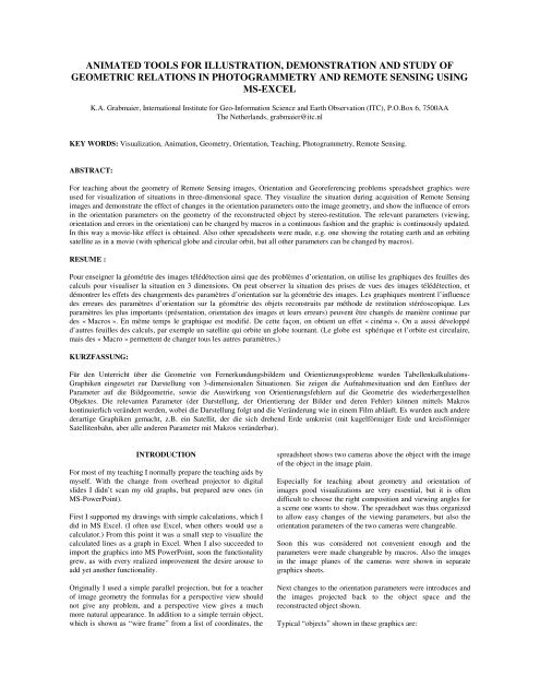
ANIMATED TOOLS FOR ILLUSTRATION, DEMONSTRATION AND STUDY OF<br />
GEOMETRIC RELATIONS IN PHOTOGRAMMETRY AND REMOTE SENSING USING<br />
MS-EXCEL<br />
K.A. Grabmaier, International Institute for Geo-Information Science and Earth Observation (<strong>ITC</strong>), P.O.Box 6, 7500AA<br />
The Netherlands, grabmaier@itc.nl<br />
KEY WORDS: Visualization, Animation, Geometry, Orientation, Teaching, Photogrammetry, Remote Sensing.<br />
ABSTRACT:<br />
For teaching about the geometry of Remote Sensing images, Orientation and Georeferencing problems spreadsheet graphics were<br />
used for visualization of situations in three-dimensional space. They visualize the situation during acquisition of Remote Sensing<br />
images and demonstrate the effect of changes in the orientation parameters onto the image geometry, and show the influence of errors<br />
in the orientation parameters on the geometry of the reconstructed object by stereo-restitution. The relevant parameters (viewing,<br />
orientation and errors in the orientation) can be changed by macros in a continuous fashion and the graphic is continuously updated.<br />
In this way a movie-like effect is obtained. Also other spreadsheets were made, e.g. one showing the rotating earth and an orbiting<br />
satellite as in a movie (with spherical globe and circular orbit, but all other parameters can be changed by macros).<br />
RESUME :<br />
Pour enseigner la géométrie des images télédétection ainsi que des problèmes d’orientation, on utilise les graphiques des feuilles des<br />
calculs pour visualiser la situation en 3 dimensions. On peut observer la situation des prises de vues des images télédétection, et<br />
démontrer les effets des changements des paramètres d’orientation sur la géométrie des images. Les graphiques montrent l’influence<br />
des erreurs des paramètres d’orientation sur la géométrie des objets reconstruits par méthode de restitution stéréoscopique. Les<br />
paramètres les plus importants (présentation, orientation des images et leurs erreurs) peuvent être changés de manière continue par<br />
des « Macros ». En même temps le graphique est modifié. De cette façon, on obtient un effet « cinéma ». On a aussi développé<br />
d’autres feuilles des calculs, par exemple un satellite qui orbite un globe tournant. (Le globe est sphérique et l’orbite est circulaire,<br />
mais des « Macro » permettent de changer tous les autres paramètres.)<br />
KURZFASSUNG:<br />
Für den Unterricht über die Geometrie von Fernerkundungsbildern und Orientierungsprobleme wurden Tabellenkalkulations-<br />
Graphiken eingesetzt zur Darstellung von 3-dimensionalen Situationen. Sie zeigen die Aufnahmesituation und den Einfluss der<br />
Parameter auf die Bildgeometrie, sowie die Auswirkung von Orientierungsfehlern auf die Geometrie des wiederhergestellten<br />
Objektes. Die relevanten Parameter (der Darstellung, der Orientierung der Bilder und deren Fehler) können mittels Makros<br />
kontinuierlich verändert werden, wobei die Darstellung folgt und die Veränderung wie in einem Film abläuft. Es wurden auch andere<br />
derartige Graphiken gemacht, z.B. ein Satellit, der die sich drehend Erde umkreist (mit kugelförmiger Erde und kreisförmiger<br />
Satellitenbahn, aber alle anderen Parameter mit Makros veränderbar).<br />
INTRODUCTION<br />
For most of my teaching I normally prepare the teaching aids by<br />
myself. With the change from overhead projector to digital<br />
slides I didn’t scan my old graphs, but prepared new ones (in<br />
MS-PowerPoint).<br />
First I supported my drawings with simple calculations, which I<br />
did in MS Excel. (I often use Excel, when others would use a<br />
calculator.) From this point it was a small step to visualize the<br />
calculated lines as a graph in Excel. When I also succeeded to<br />
import the graphics into MS PowerPoint, soon the functionality<br />
grew, as with every realized improvement the desire arouse to<br />
add yet another functionality.<br />
Originally I used a simple parallel projection, but for a teacher<br />
of image geometry the formulas for a perspective view should<br />
not give any problem, and a perspective view gives a much<br />
more natural appearance. In addition to a simple terrain object,<br />
which is shown as “wire frame” from a list of coordinates, the<br />
spreadsheet shows two cameras above the object with the image<br />
of the object in the image plain.<br />
Especially for teaching about geometry and orientation of<br />
images good visualizations are very essential, but it is often<br />
difficult to choose the right composition and viewing angles for<br />
a scene one wants to show. The spreadsheet was thus organized<br />
to allow easy changes of the viewing parameters, but also the<br />
orientation parameters of the two cameras were changeable.<br />
Soon this was considered not convenient enough and the<br />
parameters were made changeable by macros. Also the images<br />
in the image planes of the cameras were shown in separate<br />
graphics sheets.<br />
Next changes to the orientation parameters were introduces and<br />
the images projected back to the object space and the<br />
reconstructed object shown.<br />
Typical “objects” shown in these graphics are:
• A box connecting points in a rectangular pattern of<br />
3 x 3 x 2;<br />
• A group of 9 high rise, flat roof buildings with a road<br />
along them;<br />
• A landscape with a road, a house and a lake;<br />
• A regular grid DTM pattern.<br />
A version with the same functionality for push broom scanner<br />
images is not yet finalized but a variety of spreadsheets with<br />
similar principles was produced to show:<br />
• A satellite orbiting a rotating globe,<br />
• The principle of a laser scanner,<br />
• Geometric transformations of square grid patterns,<br />
• A geocentric and a local coordinate system.<br />
The spreadsheets can be used directly to show the changing<br />
graphics in Excel, but the graphics can also be imported into<br />
other software, to prepare digital slides or illustrations in a <strong>text</strong><br />
file.<br />
MS Excel, MS Visual Basic and MS PowerPoint are products<br />
of Microsoft Corporation.<br />
Perspective View<br />
REALIZATION<br />
With the usual (photogrammetric) camera parameters the<br />
functionality was disappointing, as rotations of the camera<br />
made the object move out of the field of view. I therefore<br />
changed the calculations such, that the rotation axes did not<br />
pass through the projection center (O), but through the “viewed<br />
point” (M), which one can best choose in the middle of the<br />
object area. The projection center (O) is calculated such, that<br />
point M is in the camera axis, at a distance (D) from O, which is<br />
variable by the user. In addition to the three angles of rotation,<br />
the coordinates of “M” and the distance “D”, the user can<br />
specify:<br />
• The image coordinates of the image of point M (xm,<br />
ym), being the coordinates of the principal point,<br />
• The “image scale” (s), being the ratio between the<br />
principal distance and the “object distance” (D).<br />
This gave the functionality, that the object remained in view<br />
with angular changes, and the “object distance” controlled the<br />
amount of perspectivity in the image, without changing its size.<br />
r11<br />
⋅ (U − U<br />
M<br />
) + r12<br />
⋅ (V −VM<br />
) + r13<br />
⋅ (W − WM<br />
)<br />
x = D ⋅ s ⋅<br />
+ xm (1)<br />
r ⋅ (U − U ) + r ⋅ (V −V<br />
) + r ⋅ (W − W ) + D<br />
21<br />
r31<br />
⋅ (U − U<br />
M<br />
) + r32<br />
⋅ (V −VM<br />
) + r33<br />
⋅ (W − WM<br />
)<br />
y = D ⋅ s ⋅<br />
+ ym<br />
r ⋅ (U − U ) + r ⋅ (V −V<br />
) + r ⋅ (W − W ) + D<br />
where<br />
21<br />
M<br />
M<br />
22<br />
22<br />
M<br />
M<br />
x, y = image coordinates<br />
xm, ym = coordinates of principal point<br />
D = object distance<br />
s = image scale<br />
r ij = elements of rotation matrix<br />
U M , V M , W M = coordinates of “view point” (M)<br />
U, V, W = object coordinates of any point<br />
In the case of zero rotations (as the view from O’ in figure 1.)<br />
the viewing is in the V-direction, while x is parallel to U and y<br />
is parallel to W. Different from the usual situation in terrestrial<br />
photogrammetry, Kappa rotates the view around an axis parallel<br />
to the W-axis, thus allows to “dance” around the object, while<br />
Omega inclines the direction of viewing (up or down).<br />
Movie like motion<br />
To find good viewing parameters by typing new values was far<br />
from optimal, so I developed a few macros to allow easy change<br />
of the parameters. Not familiar with Visual Basic, I simply<br />
recorded a macro to add (and another to subtract) the value of a<br />
particular cell from the selected one by “Paste Special”. The<br />
letter I assigned to the macro was simply the one in the left<br />
upper corner of the keyboard, the letter “Q”.<br />
Later I changed the macros for more robustness, but the<br />
principle remained the same: the value of a particular cell, the<br />
“increment” was added to selected one by pressing “Ctrl-Q”<br />
and it was subtracted by pressing “Ctrl-Shift-Q”. When the keycombination<br />
is held, then the increment is added (or subtracted)<br />
repeatedly. The graphics, which are visible in other windows<br />
are continuously updated, which creates an almost continuous<br />
motion. The speed of the motion depends on the “increment”.<br />
Also for changing this “increment” a macro was made, using<br />
the next letter in the row, the “W”. “Ctrl-W” will multiply it by<br />
10 and “Ctrl-Shift-W” will divide it by 10, but the macros will<br />
not set values outside the range from 0.001 to 10.<br />
In this situation the sheet containing the parameters must be<br />
open in window number 1 of the spreadsheet and the parameter<br />
to change must be selected there. Another approach using much<br />
more macros, in order to allow selection of parameters,<br />
incrementing them and changing the speed without having the<br />
parameters visible on the screen is presently under construction.<br />
23<br />
23<br />
M<br />
M<br />
O’<br />
O”<br />
W<br />
V<br />
M<br />
U<br />
P<br />
Camera(s) above the object<br />
In order to show the relief- and tilt-displacement, which has to<br />
be corrected in orthophoto production I wanted to show a DTMgrid<br />
together with its image in a camera above it, so I had to<br />
calculate the imaging of the DTM grid into the image plane of<br />
the camera. The orientation parameters of the camera were<br />
added to the parameters sheet, thus they were variable using the<br />
same macros. The typical photogrammetric parameters of<br />
interior and exterior orientation were used, but object<br />
coordinates of the image points had to be calculated rather than<br />
image coordinates.<br />
Figure 1. Two views to the same “view point” (M)<br />
The formulas used are:
the object point and the projection center – with the image<br />
plane. There is a critical plane, which is parallel to the image<br />
plane and passes through the projection center. Object points in<br />
this plane are theoretically imaged infinitely far away,<br />
practically a “Division by zero” error happens and they will be<br />
imaged to position (0, 0). Points just a little in front of this plane<br />
will be imaged very far away to one side, while points just<br />
behind it will be far away to the other side. A perhaps short<br />
joining line of two such points (on either side of the critical<br />
plane) can thus result in a very long image line!<br />
Figure 2. DTM-grid with two cameras above.<br />
To visualize the camera a square image frame was shown, and<br />
the corners of the square were connected with the projection<br />
center of the camera. Adding a second camera was simple, so<br />
this was done as well. Also the vertical projection of the DTMgrid<br />
onto a horizontal plane is shown. A typical graph obtained<br />
with this sheet is shown in figure 2.<br />
The resolution is better than shown here, but the shape of the<br />
“deformed” grid in the images did not show up well enough. To<br />
show this in a better way, separate graphics were created for<br />
each image to show the “image” itself with good resolution.<br />
Now however, the coordinates of the image points had also to<br />
be calculated in the image coordinate system.<br />
Figure 4. landscape with image 2 partly “outside”.<br />
This only happens, if the critical plane passes through the object<br />
area. The effect was considered rather curious than nasty, as<br />
such extreme situations were not meant to be used. For more<br />
“normal” situations the fact that part of the drawing is outside<br />
the image frame can sometimes be considered illustrative for the<br />
danger of errors in the coverage by errors in the camera<br />
inclination.<br />
Restitution<br />
To demonstrate the effect of orientation errors on the geometry<br />
of the restituted object another set of cameras (restitution<br />
cameras) was introduced. The differences between the<br />
parameters of the restitution cameras and those of the original<br />
cameras are kept as parameters in the parameter sheet, being the<br />
“changes to the original parameters”.<br />
Figure 3. “image” graphic of a DTM-grid.<br />
No attempt was made to limit the drawing of the image to the<br />
inside of the image frame or in any other way.<br />
In a new calculation sheet the changed parameters were<br />
calculated, then for each image point its location in the object<br />
coordinate system was calculated using those changed<br />
parameters of the camera.<br />
This gives rather strange situations in extreme cases, as<br />
mathematically the image plane is unlimited and image points<br />
are calculated as the intersection of a straight line – defined by
(U,W)-plane. For horizontal camera axes or for a base in V-<br />
direction it is not suitable. Strict formulas were tried, but<br />
considered too cumbersome.<br />
Two different V-coordinates were calculated, one for each one<br />
of the straight lines. The mean of them is used - together with<br />
the U- and W-coordinate from the intersection calculation - to<br />
show the point in the graph. The difference of the two V-values<br />
is used as “Y-parallax”.<br />
The sheet calculating the actual graph uses the calculated<br />
coordinates to show the restituted locations and allows also to<br />
show the y-parallax with a user selectable exaggeration factor.<br />
This can also be used to show the principle of analogue<br />
orientations. One can exaggerate the y-parallaxes so much, that<br />
even small ones are visible, and then one can vary the “changes<br />
to the parameters” to eliminate or reduce those parallaxes. One<br />
can also add a sheet showing only the values of the y-parallaxes<br />
of selected points (e.g. the 6 “standard” points) and show this in<br />
an additional window.<br />
Figure 5. Original and restituted object and the cameras.<br />
ui<br />
<br />
vi<br />
= Ri<br />
<br />
w<br />
<br />
i <br />
x<br />
⋅ y<br />
<br />
<br />
i<br />
i<br />
−<br />
−<br />
c<br />
xhi<br />
<br />
yhi<br />
<br />
<br />
i<br />
(2)<br />
where<br />
u, v, w = vector from projection center to image point<br />
in the object coordinate system<br />
R = rotation matrix from the changed angles<br />
x, y = image coordinates of image points<br />
xh, yh = image coordinates of the principal point<br />
i = index of the image (1 or 2)<br />
For the calculation of the point of intersection the simplified<br />
approach, which is mostly used for single models in photogrammetry<br />
was used: intersection of the two straight lines only in<br />
2D-space (U,W).<br />
U = t ⋅ u + U<br />
1<br />
2<br />
1<br />
1<br />
1<br />
(U<br />
t =<br />
1<br />
1<br />
1<br />
o ,2<br />
(U<br />
t =<br />
o ,2<br />
1<br />
1<br />
V = (V + V<br />
− U<br />
− U<br />
2<br />
o ,1<br />
W = t ⋅ w + W<br />
o ,1<br />
o ,1<br />
V = t ⋅ v + V<br />
where<br />
o ,1<br />
o ,1<br />
1<br />
1<br />
) / 2<br />
= t ⋅ u + U<br />
,<br />
2<br />
2<br />
2<br />
2<br />
1<br />
2<br />
2<br />
2<br />
y<br />
2<br />
) ⋅ w − (W<br />
2<br />
2<br />
o ,2<br />
) ⋅ w − (W<br />
o ,2<br />
2<br />
o ,2<br />
= t ⋅ w + W<br />
u ⋅ w − u ⋅ w<br />
u ⋅ w − u ⋅ w<br />
2<br />
1<br />
1<br />
o ,2<br />
−W<br />
−W<br />
2<br />
o ,1<br />
o ,1<br />
, V = t ⋅ v + V<br />
p = V −V<br />
1<br />
) ⋅ u<br />
o ,2<br />
2<br />
) ⋅ u<br />
1<br />
(3)<br />
U, V, W = object coordinates of the restituted points<br />
u, v, w = vector from projection center to image point<br />
in the object coordinate system<br />
U o,i , V o,i , W o,i = coordinates of projection center (i)<br />
t = scale factor<br />
V i = V calculated from image i<br />
i = index of the image (1 or 2)<br />
Push broom scanner(s)<br />
Figure 6. Analogue “Common Phi” .<br />
The functionality of the graphics for push broom scanner<br />
images is limited. One version shows cameras with parallel<br />
projection in one direction and central projection in the other.<br />
This limits the sensor to a straight flight path and does not allow<br />
variation of the angles within an image. The overview graph as<br />
well as view(s) of the image(s) are available, but restitution<br />
with changed parameters is not yet possible.<br />
This works fine as long as the joining lines of the two projection<br />
centers and the two camera axes do not deviate much from the
to show it at the congress. The transformation from object to<br />
image is not straight forward in that case, because the<br />
orientation parameters to be used depend on the image line, in<br />
which the point is imaged. This requires iterative calculation or<br />
higher order rational polynoms. Iterative calculation with three<br />
iterations will be used. This should give satisfactory results. To<br />
allow all possible constellations, the restitution will make use of<br />
concise formulas for the intersection of the rays such, that the<br />
joining line of the resulting points on each light ray is<br />
perpendicular to both light rays.<br />
Figure 7. Two push broom views (forward and backward).<br />
Another version shows a series of “line imaging events”. Each<br />
event is shown by four lines only:<br />
• A straight and horizontal line in the object space,<br />
• Two imaging rays for the extreme points<br />
• The sensor line.<br />
In this case the flight path and the rotation angles are modelled<br />
by a second order polynomial. There is no object shown and no<br />
image.<br />
U<br />
i U<br />
o<br />
<br />
<br />
Vi<br />
<br />
=<br />
<br />
Vo<br />
<br />
W <br />
<br />
i Wo<br />
t1<br />
u1<br />
<br />
=<br />
<br />
<br />
t2<br />
<br />
v2<br />
<br />
t <br />
<br />
3 w1<br />
where<br />
, i<br />
, i<br />
, i<br />
ui<br />
<br />
<br />
<br />
+ ti<br />
⋅<br />
<br />
vi<br />
<br />
<br />
<br />
<br />
w <br />
i <br />
− u<br />
2<br />
− v<br />
2<br />
− w<br />
2<br />
−1<br />
( v1<br />
⋅ w2<br />
− w1<br />
⋅v2)<br />
U<br />
o<br />
<br />
( w1<br />
⋅u2<br />
− u1<br />
⋅ w2<br />
)<br />
<br />
⋅<br />
<br />
Vo<br />
( u ⋅ − ⋅ <br />
<br />
1<br />
v2<br />
v1<br />
u2)<br />
Wo<br />
,2<br />
,2<br />
,2<br />
−U<br />
−V<br />
o,1<br />
−W<br />
o,1<br />
o,1<br />
<br />
<br />
<br />
<br />
<br />
(4)<br />
U i , V i , W i = object coordinates of the restituted point,<br />
calculated from image i<br />
u i , v i , w i = vector in image i from projection center to<br />
image point in the object coordinate system<br />
U o,i , V o,i , W o,i = coordinates of projection center (i)<br />
t i = scale factors<br />
i = index of the image (1 or 2)<br />
OTHER GRAPHICS<br />
Orbiting Satellite<br />
Figure 8. Push broom imaging events and parameters<br />
There were no macros made to handle the parameters in this<br />
version, as the speed of changes in zero order, first order and<br />
second order terms is incompatible. A better choice of the units<br />
could probably overcome this problem, but there are much more<br />
changes foreseen: It should become an imaging version and also<br />
restitution with changed parameters should become possible.<br />
The concepts and layouts are ready since some time, but the<br />
time to implement it was not available so far. I hope to be able<br />
Figure 9. orbiting satellite and globe (showing The Netherlands)<br />
This graphic shows a spherical globe and a circular satellite<br />
orbit. The following parameters can be changed “continuously”<br />
by macros: all viewing parameters, the radius of the globe and<br />
its speed of rotation, the height and the inclination of the orbit,<br />
the position of the satellite at time “zero”, the (angular) speed of<br />
the satellite, the swath (angle), the forward and the sideward<br />
look angle, the “time”(in minutes).<br />
When the time changes, then the globe rotates and the satellite<br />
moves, both according to the speeds specified.
Laser Scanning<br />
This graphic shows the deflection of a laser beam by a rotating<br />
prism.<br />
For output driven resampling the grid pattern shows the pixels,<br />
which should be created and the circles show the positions of<br />
the pixel centers of the existing image transformed to the new<br />
geometry. When changing the parameters using the macros one<br />
can nicely demonstrate the effect of each one, like shift, change<br />
of scale, shear etcetera.<br />
Local and global coordinates<br />
For the illustration of the relations between a local and a global<br />
“Cartesian” coordinate system another spreadsheet was made. It<br />
shows a (spherical) globe, the axes of the geocentric coordinate<br />
system, the “local” meridian and the axes of the local coordinate<br />
system together with a horizontal square around the local origin.<br />
Figure 10. laser scanning principle<br />
The user can rotate the prism, change the number of facets<br />
(between 3 and 20), and the speed of motion (30 to 3 steps per<br />
facet). After a change of the number of facets the reflection may<br />
be wrong such, that a reflection is shown outside the limits of a<br />
facet. After the rotation starts, this is corrected.<br />
Besides the viewing parameters one can change the size of the<br />
globe, the longitude and the latitude of the local origin and the<br />
size of the horizontal square by macros. The size of the<br />
coordinate axes shown depend on those settings. The global<br />
axes are 20% longer than the radius of the globe, while the local<br />
axes are equal to the sides of the square.<br />
Transformations of square grid patterns<br />
This graphic was made to illustrate the principles of resampling.<br />
Bilinear transformation is used here:<br />
x = a0 + a1 ⋅ c + a2 ⋅ r + a3 ⋅ c ⋅ r<br />
(5)<br />
y = a4 + a5 ⋅ c + a6 ⋅ r + a7 ⋅ c ⋅ r<br />
where<br />
c, r = column and row coordinates<br />
x, y = output coordinates<br />
a0 to a7 = transformation parameters<br />
Figure 12. local and global coodinates<br />
Conclusions and Outlook<br />
Spreadsheet graphics offer an easy tool to visualize objects and<br />
relations in 3D-space to anyone familiar with the spreadsheet<br />
software. This can be used to make “nice” teaching aids, but<br />
they can also be used as a teaching aid by themselves.<br />
The use of macros to easily increment or decrement some<br />
parameters can make it easy to select suitable parameters to use<br />
the graphic elsewhere, but they are even more valuable when<br />
using the spreadsheet itself as teaching aid, as it allows to show<br />
the effect of changes in a “continuous” mode.<br />
Figure 11. image transformation<br />
The parameters (a0 to a7) can be varied using macros. For<br />
affine transformation one can simply set the parameters a3 and<br />
a7 to zero, but for conformal transformation a modification of<br />
the sheet would be useful to couple a5 to a2 and a6 to a1.<br />
PowerPoint slides I have made with these tools are appreciated<br />
by students as well as colleagues, I have found these graphics in<br />
numerous presentations of colleagues.<br />
Besides the completion of the push broom functionality a<br />
version is envisaged to give two views from different positions,<br />
one in red and one in cyan, for stereoscopic viewing using the<br />
anaglyph principle.