
You also want an ePaper? Increase the reach of your titles
YUMPU automatically turns print PDFs into web optimized ePapers that Google loves.
_ V<strong>1.2</strong><br />
Hardware Reference<br />
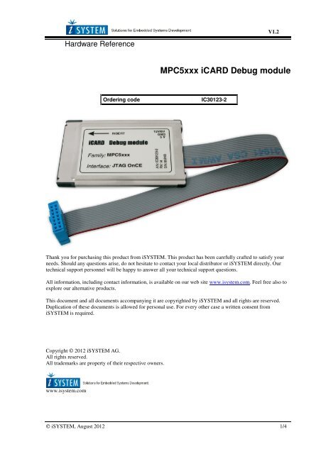
MPC5xxx <strong>iCARD</strong> Debug module<br />
Ordering code<br />
IC30123-2<br />
Thank you for purchasing this product from <strong>iSYSTEM</strong>. This product has been carefully crafted to satisfy your<br />
needs. Should any questions arise, do not hesitate to contact your local distributor or <strong>iSYSTEM</strong> directly. Our<br />
technical support personnel will be happy to answer all your technical support questions.<br />
All information, including contact information, is available on our web site www.isystem.com. Feel free also to<br />
explore our alternative products.<br />
This document and all documents accompanying it are copyrighted by <strong>iSYSTEM</strong> and all rights are reserved.<br />
Duplication of these documents is allowed for personal use. For every other case a written consent from<br />
<strong>iSYSTEM</strong> is required.<br />
Copyright © 2012 <strong>iSYSTEM</strong> AG.<br />
All rights reserved.<br />
All trademarks are property of their respective owners.<br />
www.isystem.com<br />
© <strong>iSYSTEM</strong>, August 2012 1/4
_<br />
POD Hardware Reference<br />
iCard<br />
The iC3000 support a wide range of serial debug interfaces like Motorola's Background Debug Mode (BDM),<br />
the Serial Debug Interface (SDI) and the On-Chip Emulation (OnCE) interface. JTAG based debug interfaces are<br />
also supported by these Emulators. For each specific debug interface a special <strong>iCARD</strong> is available.<br />
The <strong>iCARD</strong> is a PCMCIA-style interface card which contains all necessary adaptations including the target<br />
interface cable for a selected serial debug interface. The <strong>iCARD</strong> plugs into the PCMCIA-style card slot of the<br />
iC3000 unit. Features like on-chip-, in-system programming and programming voltage generation are standard<br />
features.<br />
Note: Whenever connecting to the target both target and the Emulator must be switched off. The Emulator is first<br />
switched on, and the target right afterwards. Note that otherwise during connecting the target a massive current<br />
spike may flow during static discharge or ground potential equalization.<br />
On some debugging iCards beside the interface specific cable there's a 3-pin connector. The 5V/300mA output<br />
provides power to small low-power targets. On some iCards, also the 12V/60mA programming voltage is<br />
available and also generated by the iC3000 development system and routed to the <strong>iCARD</strong>'s 3-pin connector.<br />
Note that the 12V output is controlled by the software. The output defaults to 5V. On the iC3000 the current for<br />
12V flows from the 5V source. Thus, a 12V/50mA load represents 120mA load on the 5V power source. Note<br />
that on interface cards for ActiveEmulator, iTRACE and similar this connector is not available, and also on some<br />
iCards, the 12V output is not available since it is not needed.<br />
When not in use, the <strong>iCARD</strong> should be kept in its protective antistatic bag to ensure its dependability and keep<br />
the 68-pin PC-Card connector clean.<br />
The iCard is a delicate piece of equipment. Always handle it with care, make sure not to bend it or deform<br />
it in any way, to keep it clean, etc. If these instructions are not followed, damage to the iCard or the<br />
Emulator can occur.<br />
Note: Despite using the same format, <strong>iCARD</strong>s are not pin compatible with PCMCIA cards. Do NOT use<br />
<strong>iCARD</strong>s in PCMCIA slots and vice-versa! If the <strong>iCARD</strong> is inserted into a PCMCIA slot, damage to the <strong>iCARD</strong><br />
and/or the PCMCIA slot will occur. If a PCMCIA card is inserted into the <strong>iCARD</strong> slot, damage to the PCMCIA<br />
card and/or the Emulator will occur.<br />
Temperature range<br />
All <strong>iSYSTEM</strong> devices, unless explicitly otherwise noted, are specified to operate at room temperatures<br />
(specifically, between 10°C/50°F and 40°C/105°F).<br />
© <strong>iSYSTEM</strong>, August 2012 2/4
_<br />
Hardware Reference<br />
MPC5xxx <strong>iCARD</strong> Debug module<br />
Ordering code<br />
Dimensions (WxLxH, mm)<br />
IC30123-2<br />
54x84x5<br />
Supported devices<br />
<strong>MPC55xx</strong><br />
MPC551x<br />
xPC56xx<br />
MPC564x<br />
MPC567x<br />
MPC57xx<br />
Check with <strong>iSYSTEM</strong> for the latest list of supported devices.<br />
The following pinout is valid on the target side:<br />
2 4 6 8 10 12 14<br />
GND GND GND N.C. TMS GND JCOMP<br />
TDI TDO TCK EVTIN RESET VDD RDY<br />
1 3 5 7 9 11 13<br />
MPC5xxx OnCE/JTAG pinout<br />
All pins except pin 8 and RDY (pin13) are connected and used by <strong>iCARD</strong>. Mandatory pins on the<br />
microcontroller side:<br />
- GND, VDD, RESET, TMS, TDI, TDO, TCK<br />
JCOMP is an optional pin. Some microcontrollers don’t have this pin. Internally, this is actually JTAG TRST<br />
which resets JTAG (TAP) state machine. Because JTAG can be reset also by TMS and TCK, this pin is optional<br />
also for winIDEA.<br />
If the target microcontroller has JCOMP pin but it’s not connected to the target JTAG debug connector then it<br />
must be set to non active state in the target via a pull-up resistor. If not then TAP remains in reset and debugging<br />
is not possible.<br />
© <strong>iSYSTEM</strong>, August 2012 3/4
EVTIN pin 7 is driven high by the debugger. In general, the target JTAG debug connector doesn’t have this pin<br />
connected. However, there will be an electrical conflict if the target microcontroller Nexus pin EVTIN connects<br />
to the pin 7 of the target debug connector and at the same time this microcontroller pin is configured for I/O<br />
operation and not for Nexus port operation. Note that if the microcontroller EVTIN pin is used as an I/O pin,<br />
it must not be connected to the target JTAG debug connector!<br />
Adapters<br />
Ordering code<br />
IAPIN14MPCMIC38<br />
Per default, the JTAG debugger connects to a 14-pin target debug connector<br />
(2.54 mm pitch), which connects to the CPU JTAG debug port. In order to<br />
save space in the target, the target may provide only a Mictor38 connector,<br />
which connects to the <strong>MPC55xx</strong> Nexus debug port. In such cases, the user can<br />
order separately the IAPIN14MPCMIC38 adapter, through which the JTAG<br />
debugger can be also connected to the target <strong>MPC55xx</strong> Nexus debug<br />
connector (Mictor 38).<br />
Notes<br />
• On Freescale and ST xPC56xx devices, the RESET pin is bidirectional while with other devices<br />
(<strong>MPC55xx</strong>) it’s input to the CPU only (no feedback on the CPU reset can be reported to the debugger).<br />
• If the debugged target device has a separate power supply for the on-chip debug module then this power<br />
supply must be connected to the target debug connector (pin 11).<br />
• This <strong>iCARD</strong> supports <strong>MPC55xx</strong>, xPC56xx and MPC57xx debugging. Note that for multi core<br />
debugging an additional software license is required.<br />
Important Information<br />
Note also the direction in which the <strong>iCARD</strong> is inserted into the <strong>iCARD</strong> slot. The side with the label is the top<br />
side; the arrow shows the direction in which the <strong>iCARD</strong> should be inserted.<br />
Disclaimer: <strong>iSYSTEM</strong> assumes no responsibility for any errors which may appear in this document, reserves the<br />
right to change devices or specifications detailed herein at any time without notice, and does not make any<br />
commitment to update the information herein.<br />
© <strong>iSYSTEM</strong>. All rights reserved.<br />
© <strong>iSYSTEM</strong>, August 2012 4/4