
Create successful ePaper yourself
Turn your PDF publications into a flip-book with our unique Google optimized e-Paper software.
_ <strong>V1.3</strong><br />
Hardware Reference<br />
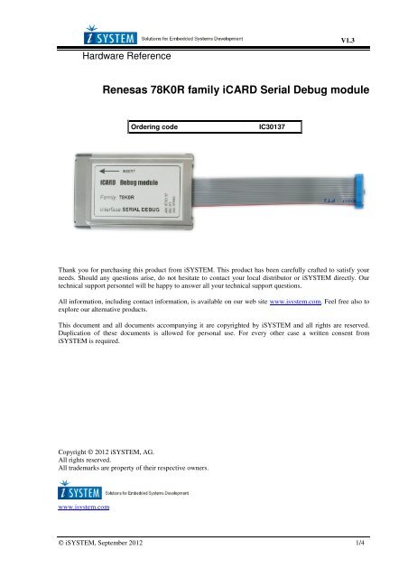
Renesas <strong>78K0R</strong> family <strong>iCARD</strong> Serial Debug module<br />
Ordering code<br />
IC30137<br />
Thank you for purchasing this product from <strong>iSYSTEM</strong>. This product has been carefully crafted to satisfy your<br />
needs. Should any questions arise, do not hesitate to contact your local distributor or <strong>iSYSTEM</strong> directly. Our<br />
technical support personnel will be happy to answer all your technical support questions.<br />
All information, including contact information, is available on our web site www.isystem.com. Feel free also to<br />
explore our alternative products.<br />
This document and all documents accompanying it are copyrighted by <strong>iSYSTEM</strong> and all rights are reserved.<br />
Duplication of these documents is allowed for personal use. For every other case a written consent from<br />
<strong>iSYSTEM</strong> is required.<br />
Copyright © 2012 <strong>iSYSTEM</strong>, AG.<br />
All rights reserved.<br />
All trademarks are property of their respective owners.<br />
www.isystem.com<br />
© <strong>iSYSTEM</strong>, September 2012 1/4
_<br />
TECHNICAL SPECIFICATION<br />
iCard General Notes<br />
The iC3000 support a wide range of serial debug interfaces like Motorola's Background Debug Mode (BDM),<br />
the Serial Debug Interface (SDI) and the On-Chip Emulation (OnCE) interface. JTAG based debug interfaces are<br />
also supported by these Emulators. For each specific debug interface a special <strong>iCARD</strong> is available.<br />
The <strong>iCARD</strong> is a PCMCIA-style interface card which contains all necessary adaptations including the target<br />
interface cable for a selected serial debug interface. The <strong>iCARD</strong> plugs into the PCMCIA-style card slot of the<br />
iC3000 unit. Features like on-chip-, in-system programming and programming voltage generation are standard<br />
features.<br />
Note: Whenever connecting to the target both target and the Emulator must be switched off. The Emulator is first<br />
switched on, and the target right afterwards. Note that otherwise during connecting the target a massive current<br />
spike may flow during static discharge or ground potential equalization.<br />
On some debugging iCards beside the interface specific cable there's a 3-pin connector. The 5V/300mA output<br />
provides power to small low-power targets. On some iCards, also the 12V/60mA programming voltage is<br />
available and also generated by the iC3000 development system and routed to the <strong>iCARD</strong>'s 3-pin connector.<br />
Note that the 12V output is controlled by the software. The output defaults to 5V. On the iC3000 the current for<br />
12V flows from the 5V source. Thus, a 12V/50mA load represents 120mA load on the 5V power source. Note<br />
that on interface cards for ActiveEmulator, iTRACE and similar this connector is not available, and also on some<br />
iCards, the 12V output is not available since it is not needed.<br />
When not in use, the <strong>iCARD</strong> should be kept in its protective antistatic bag to ensure its dependability and keep<br />
the 68-pin PC-Card connector clean.<br />
The iCard is a delicate piece of equipment. Always handle it with care, make sure not to bend it or deform<br />
it in any way, to keep it clean, etc. If these instructions are not followed, damage to the iCard or the<br />
Emulator can occur.<br />
Note: Despite using the same format, <strong>iCARD</strong>s are not pin compatible with PCMCIA cards. Do NOT use<br />
<strong>iCARD</strong>s in PCMCIA slots and vice-versa! If the <strong>iCARD</strong> is inserted into a PCMCIA slot, damage to the <strong>iCARD</strong><br />
and/or the PCMCIA slot will occur. If a PCMCIA card is inserted into the <strong>iCARD</strong> slot, damage to the PCMCIA<br />
card and/or the Emulator will occur.<br />
Temperature range<br />
All <strong>iSYSTEM</strong> devices, unless explicitly otherwise noted, are specified to operate at room temperatures<br />
(specifically, between 10°C/50°F and 40°C/105°F).<br />
© <strong>iSYSTEM</strong>, September 2012 2/4
_<br />
TECHNICAL SPECIFICATION<br />
Renesas <strong>78K0R</strong> family <strong>iCARD</strong> Serial Debug module<br />
Ordering code<br />
Dimensions (WxLxH, mm)<br />
IC30137<br />
54x84x5<br />
Note This debug <strong>iCARD</strong> is supported by iC3000HS and iC3000GT. Earlier iC3000 units (ordering code<br />
iC30000/IC30001) do not support this debug <strong>iCARD</strong>.<br />
Supported CPUs<br />
uPD78F1804- uPD78F1845<br />
Please check with your local <strong>iSYSTEM</strong> sales representative for the latest list of supported CPUs.<br />
The following pinout is valid on the target side:<br />
Signal<br />
direction<br />
I/O<br />
I/O<br />
Signal description Signal Pin Pin Signal Signal description Signal<br />
direction<br />
Ground GND 1 2 RESET OUT Reset Out O<br />
Communication TOOL0 3 4 Vcc Power Supply I/O<br />
line (RxD/TxD)<br />
Communication TOOL0 5 6 NC Not Connected<br />
line (RxD/TxD)<br />
Not Connected NC 7 8 NC Not Connected<br />
Not Connected NC 9 10 NC Not Connected<br />
Not Connected NC 11 12 NC Not Connected<br />
Not Connected NC 13 14 FLMD0 Flash Mode O<br />
I Reset In RESET IN 15 16 TOOL1 (CLK) Clock Input I<br />
16-pin Renesas <strong>78K0R</strong> Serial Debug target pinout<br />
If the ‘Supply 5V to the target’ option is checked in the ‘Hardware/Emulation Options/CPU Setup/Advanced’<br />
tab, the debugger supplies 5V at Vcc pin (pin 4) of the target debug connector, which can be used to power the<br />
target. Maximum target current consumption should not exceed 50mA.<br />
© <strong>iSYSTEM</strong>, September 2012 3/4
Signal direction definition:<br />
O<br />
I<br />
- output from the debugger to the target microcontroller<br />
- input to the debugger from the target microcontroller<br />
Note: If ‘RESET IN’ (target reset detection) is not connected to the target debug connector, make sure that 10k<br />
pull up is connected to this pin (target debug connector pin 15) or the debugger may exhibit unpredictable<br />
behaviour.<br />
Disclaimer: <strong>iSYSTEM</strong> assumes no responsibility for any errors which may appear in this document, reserves the<br />
right to change devices or specifications detailed herein at any time without notice, and does not make any<br />
commitment to update the information herein.<br />
© <strong>iSYSTEM</strong>. All rights reserved.<br />
© <strong>iSYSTEM</strong>, September 2012 4/4