MPC5607B Nexus Emulation Board 208BGA â 176TQ - iSYSTEM
MPC5607B Nexus Emulation Board 208BGA â 176TQ - iSYSTEM
MPC5607B Nexus Emulation Board 208BGA â 176TQ - iSYSTEM

Create successful ePaper yourself
Turn your PDF publications into a flip-book with our unique Google optimized e-Paper software.
_ V1.1<br />
Adapters<br />
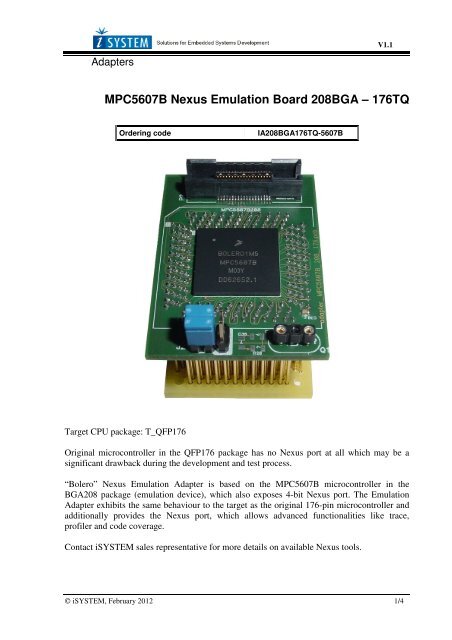
<strong>MPC5607B</strong> <strong>Nexus</strong> <strong>Emulation</strong> <strong>Board</strong> <strong>208BGA</strong> – <strong>176TQ</strong><br />
Ordering code<br />
IA<strong>208BGA</strong><strong>176TQ</strong>-5607B<br />
Target CPU package: T_QFP176<br />
Original microcontroller in the QFP176 package has no <strong>Nexus</strong> port at all which may be a<br />
significant drawback during the development and test process.<br />
“Bolero” <strong>Nexus</strong> <strong>Emulation</strong> Adapter is based on the <strong>MPC5607B</strong> microcontroller in the<br />
BGA208 package (emulation device), which also exposes 4-bit <strong>Nexus</strong> port. The <strong>Emulation</strong><br />
Adapter exhibits the same behaviour to the target as the original 176-pin microcontroller and<br />
additionally provides the <strong>Nexus</strong> port, which allows advanced functionalities like trace,<br />
profiler and code coverage.<br />
Contact <strong>iSYSTEM</strong> sales representative for more details on available <strong>Nexus</strong> tools.<br />
© <strong>iSYSTEM</strong>, February 2012 1/4
Jumper configuration<br />
J1 and J2: clock source configuration<br />
Jumpers J1 and J2 select clock source for the emulation device. Per default, both jumpers are<br />
set to position 1-2, which yields clock source being used from the emulation adapter.<br />
For the first time after receiving the emulation adapter, it is recommended that it’s tested with<br />
this setting. Once it’s confirmed that is operational, target clock use (J1 & J2 position 2-3) can<br />
be tested.<br />
Note that the emulation adapter may not operate when crystal circuit is used in the target.<br />
Typical design guideline is that a crystal should be as close as possible to the microcontroller.<br />
However, it may happen that the target crystal may not oscillate with the emulation adapter<br />
since clock lines (XTAL, EXTAL) between the target and the emulation device on the<br />
emulation adapter are prolonged. There should be no problem with the oscillator being used in<br />
the target.<br />
If an oscillator in the target is not an option and the target crystal doesn’t oscillate in<br />
conjunction with the emulation adapter, clock from the emulation adapter must be used (J1 &<br />
J2 position 1-2). In this case, a crystal circuit must be assembled on the emulation adapter.<br />
Crystal circuit<br />
Crystal circuit is located in the corner of the emulation adapter, next to the <strong>Nexus</strong> (Mictor)<br />
connector.<br />
Per default 8.2pF capacitors are populated for C30 and C31 and 8MHz crystal for Q1. R20<br />
must not be populated. Note that these values are valid for 8MHz crystal only. If different<br />
crystal is used, appropriate capacitors and resistor must be soldered (replace original ones).<br />
© <strong>iSYSTEM</strong>, February 2012 2/4
Schematic<br />
© <strong>iSYSTEM</strong>, February 2012 3/4
Disclaimer: <strong>iSYSTEM</strong> assumes no responsibility for any errors which may appear in this document, reserves the<br />
right to change devices or specifications detailed herein at any time without notice, and does not make any<br />
commitment to update the information herein.<br />
© <strong>iSYSTEM</strong>. All rights reserved.<br />
© <strong>iSYSTEM</strong>, February 2012 4/4