CAEN 2012 Products Catalog - Quantech Works
CAEN 2012 Products Catalog - Quantech Works
CAEN 2012 Products Catalog - Quantech Works

Create successful ePaper yourself
Turn your PDF publications into a flip-book with our unique Google optimized e-Paper software.
<strong>CAEN</strong> <strong>2012</strong> <strong>Products</strong> <strong>Catalog</strong><br />
Electronic Instrumentation
<strong>CAEN</strong><br />
Electronic Instrumentation<br />
<strong>2012</strong> <strong>Products</strong> <strong>Catalog</strong>
We are proud of the high quality of our products.<br />
ISO 9001<br />
ISO 9001:2008 approved quality system ensures all our internal processes.<br />
From R&D to the registration of the incoming purchase orders, through:<br />
• Resource Planning<br />
• Scheduling<br />
• Production<br />
Our quality system is responsible for the proper functioning of all our internal<br />
processes and is subject to regularly unannounced audits, carried out by the<br />
National Standards Authority.<br />
From the initial product design and its development stages, till the delivery of<br />
the production batches, we follow documented procedures that cover every<br />
aspect of our business. The auditing of our procedures by an independent<br />
third party guaranties that our business runs smoothly and efficiently.<br />
The quality of <strong>CAEN</strong> S.p.A. products is constantly monitored<br />
by the application of the UNI EN ISO 9001:2008 standard.<br />
<strong>CAEN</strong> S.p.A. is ISO 9001 certified since 1998.<br />
ISO9001:2008<br />
certified Company<br />
Authorised<br />
research laboratory<br />
of the MIUR
President’s Foreword<br />
LOOKING BEYOND THE KNOWN !<br />
Dear Friends,<br />
I have always believed in hard work based on absolute reliability and<br />
professionalism. For this reason I look at our future with great optimism.<br />
The main links which join us to our customers are curiosity and ability to look<br />
beyond the known. We are always happy to assist our customers through the<br />
years and very proud to help them to achieve the expected results.<br />
We are still motivated by the same enthusiasm of our early days. For this reason<br />
we always endeavour to offer new products and solutions and engage ourselves<br />
in new activities:<br />
- <strong>CAEN</strong>els supplies power and measurement systems for Synchrotron Light<br />
Source (SLS) laboratories.<br />
- <strong>CAEN</strong> Systems & Spectroscopy Division will soon provide instruments and<br />
systems targeted to different applications in the field of Nuclear Spectroscopy.<br />
With the same attitude that you appreciated in the past and with the precious<br />
contribution that you all gave us during the last 32 years, we are confident that<br />
we can look far ahead and successfully overcome the challenges we will face in<br />
the future, all of this in respect of the highest quality standards.<br />
A sincere thanks to you all,<br />
Marcello Givoletti<br />
<strong>CAEN</strong> President
Welcome to the <strong>2012</strong> <strong>CAEN</strong> <strong>Products</strong> <strong>Catalog</strong>!<br />
This catalog represents the state-of-the-art of <strong>CAEN</strong>’s products offering at the date of printing. To check the updated list of all our<br />
products, please visit our web site (ww.caen.it). Nevertheless, the products appearing either on the catalog or on our web site do<br />
not represent all our expertise, as almost 20% of <strong>CAEN</strong> production is custom designed.<br />
If you don’t find the Product you need in our <strong>Catalog</strong>, or if you are starting a new experiment and require a completely new design,<br />
feel free to contact us. <strong>CAEN</strong> will help you at any stage of your project.<br />
<strong>CAEN</strong> is now extending its products range:<br />
• Power Supplies:<br />
- High quality Low and High Voltage Power Supply Systems and Modules<br />
available in different form factors<br />
• NIM,VME and Desktop systems:<br />
- Complete DAQ modules from the detector to the acquisition<br />
- New firmware suites for dedicated applications<br />
• New Powered Crate Line<br />
• New Preamplifiers Line<br />
• New Complete Readout and Educational Systems<br />
• New Software Tools<br />
• New Cable Adapters<br />
Table of Contents<br />
Pages<br />
<strong>CAEN</strong> Informations ................................................... 1-12<br />
CAMAC .......................................................................... 13<br />
Desktop ......................................................................... 16<br />
Digitizers ......................................................................... 18<br />
Firmware for DPP ......................................................... 26<br />
DT5780 (Digital Multichannel Analyzer) .................. 29<br />
NIM ................................................................................. 30<br />
NIM Power Supplies ..................................................... 39<br />
VME Power Supplies ..................................................... 45<br />
Universal Multichannel Power Supply Systems ...... 46<br />
Powered Crates ............................................................ 55<br />
Preamplifiers ................................................................ 61<br />
VME ................................................................................ 64<br />
Readout Systems .......................................................... 77<br />
Silicon PhotoMultiplier Kits ......................................... 79<br />
Accessories ..................................................................... 84<br />
Application Notes ........................................................ 87<br />
Synergies ....................................................................... 88<br />
Connectors .................................................................... 91<br />
<strong>Products</strong> Handling ....................................................... 93<br />
Cross Reference Tables ................................................ 94<br />
Index ............................................................................. 102<br />
International Sales Network ..................................... 110<br />
Legend<br />
colour green = coming soon product *<br />
* The specifications description is a draft version only. The content is still under internal<br />
review and subject to formal approval, which may result in modifications or additions.<br />
colour red = new product<br />
DPP<br />
CI<br />
DPP<br />
PSD<br />
DPP<br />
PHA<br />
Indicates that the VME module is available in both<br />
6U-VME64 and 6U-VME64X form factors.<br />
Indicates that the Digitizer can run Digital Pulse Processing<br />
for the Charge Integration (DPP-CI) firmware.<br />
Indicates that the Digitizer can run Digital Pulse Processing<br />
for Pulse Shape Discrimination (DPP-PSD) firmware<br />
Indicates that the Digitizer can run Digital Pulse Processing<br />
for Pulse Height Analysis (DPP-PHA) firmware.<br />
4 Short Form <strong>Catalog</strong> <strong>2012</strong>
Network Companies<br />
Electronic Instrumentation<br />
<strong>CAEN</strong> SpA is a leader in the design and manufacture of sophisticated electronic instrumentation for Subnuclear, Nuclear<br />
and Astroparticle Physics. Our products include Low Voltage & High Voltage Power Supply Systems, Signal Conditioning,<br />
Front- End, Trigger, Data Acquisition Electronics (VME, NIM standard and Desktop) and Powered Crates. <strong>CAEN</strong> activities<br />
are at the forefront of technology also thanks to years of intensive collaborations with the major Research Centers and<br />
Universities in the world. <strong>CAEN</strong> is also proud of its extensive collaboration with the most important HEP experiments<br />
world-wide: almost 20% of our production is custom designed. To provide its customers with better assistance and<br />
services <strong>CAEN</strong> opened its new branch companies in the United States (<strong>CAEN</strong> Technologies Inc., 2005) and in Germany<br />
(<strong>CAEN</strong> GmbH, 2006).<br />
<strong>CAEN</strong> S.p.A<br />
Costruzioni Apparecchiature Elettroniche<br />
Nucleari (C.A.E.N.) is one of the most<br />
important spin-offs of the Italian Institute<br />
of Nuclear Physics (INFN).<br />
Founded in 1979 by a group of senior<br />
engineers from the INFN, is today<br />
world wide recognized as one of the<br />
leading companies in the electronics<br />
instrumentation field.<br />
<strong>CAEN</strong> Network’s Companies<br />
The <strong>CAEN</strong> Network’s Companies is<br />
a micro-cluster of companies with<br />
excellence know how.<br />
<strong>CAEN</strong> Systems and Spectroscopy Division<br />
<strong>CAEN</strong> Systems and Spectroscopy Division is a newborn entity in <strong>CAEN</strong> Electronic<br />
Instrumentation. The aim is to design advanced nuclear spectroscopy instrumentation<br />
and systems for different application fields. From Gamma to X-ray spectroscopy <strong>CAEN</strong><br />
wishes to become a valuable partner both for the users and companies willing to establish<br />
a winning team.<br />
RFID<br />
<strong>CAEN</strong> RFID is today a leading supplier of UHF RFID readers and tags. It has been<br />
among the first European companies to design and manufacture UHF RFID readers.<br />
A totally internal expertise and know-how on Radiofrequency electronics and related<br />
Software has allowed <strong>CAEN</strong> RFID to become rapidly a leader in Europe.<br />
Thanks to our R&D skills, <strong>CAEN</strong> RFID can also design specific equipment on a custom basis,<br />
thus providing RFID readers and tags for special applications on demand.<br />
<strong>CAEN</strong> Headquarters, Viareggio - Italy<br />
<strong>CAEN</strong>els<br />
<strong>CAEN</strong>els is a young and dynamic company that provides power supplies and<br />
measurement systems (Beam Position Monitoring) for Synchrotron Light Source (SLS)<br />
and Free Electron Laser (FEL) laboratories.<br />
Thanks to the technology licensed by Sincrotrone Trieste and the longstanding<br />
engineering, manufacturing and maintenance experience of <strong>CAEN</strong>, <strong>CAEN</strong>els aims to<br />
become a reliable and strategic partner for the SLS Community, able to integrate its<br />
products and support the Customers with their on-site installations.<br />
Short Form <strong>Catalog</strong> <strong>2012</strong><br />
5
Contacts and Worldwide Presence<br />
<strong>CAEN</strong> SpA<br />
Corporate Headquarters<br />
Via Vetraia 11<br />
55049 - Viareggio • Italy<br />
Phone +39.0584.388.398<br />
Fax +39.0584.388.959<br />
info@caen.it<br />
www.caen.it<br />
<strong>CAEN</strong> GmbH<br />
Eckehardweg 10<br />
42653 - Solingen • Germany<br />
Phone +49.212.2544077<br />
Fax +49.212.2544079<br />
info@caen-de.com<br />
www.caen-de.com<br />
<strong>CAEN</strong> Technologies, Inc.<br />
1140 Bay Street - Suite 2C<br />
Staten Island, NY 10305 • USA<br />
Phone +1.718.981.0401<br />
Fax +1.718.556.9185<br />
info@caentechnologies.com<br />
www.caentechnologies.com<br />
Sales Network<br />
<strong>CAEN</strong> is proud to have served many customers and research labs world wide.<br />
<strong>CAEN</strong> Network Contacts<br />
<strong>CAEN</strong> Electronic Instrumentation<br />
(Italy)<br />
Sandra Picchi<br />
Marketing Assistant<br />
s.picchi@caen.it<br />
<strong>CAEN</strong> Electronic Instrumentation<br />
(Far East)<br />
Carolina Stefani<br />
Marketing Assistant<br />
c.stefani@caen.it<br />
<strong>CAEN</strong> continues to supply its equipment to physics research centers and industrial market<br />
offering world wide sales and support.<br />
<strong>CAEN</strong> is sure to have the equipment suited to your need, and we will back it up with the<br />
best service and support in the industry.<br />
Our products appeal to a wide range of customers including engineers, scientists and<br />
technical professionals who all trust them to help achieve their goals faster and more<br />
effectively.<br />
For detailed Sales Network, please see at page 110 - 111<br />
<strong>CAEN</strong> Electronic Instrumentation<br />
(Europe - Americas)<br />
<strong>CAEN</strong>els (World)<br />
Ines Llorente<br />
Marketing Assistant<br />
i.llorente@caen.it<br />
<strong>CAEN</strong>RFID (World)<br />
Anna Del Pistoia<br />
Marketing Assistant<br />
a.delpistoia@caen.it<br />
2010 International Sales Agent Conference<br />
6 Short Form <strong>Catalog</strong> <strong>2012</strong>
Web Services<br />
Quick search<br />
The new Quick Search allows to surf our products by function in order to find<br />
in a few steps the modules that better fit your needs.<br />
My<strong>CAEN</strong><br />
<strong>CAEN</strong> offers the possibility to create a personal account to benefit of different<br />
personal services:<br />
• Download firmware and software to keep your instruments always updated<br />
• Subscribe to our newsletter<br />
• Wish List<br />
The Wish List button is very similar to the Cart button in many e-commerce<br />
websites and allows you to request a quote for the full list of products of your<br />
interest. You can also share the Wish List with your colleagues with a simple click.<br />
In addition we are working on new services to better support our customers.<br />
These new services such as the “Personal Software Licences Archive” or the<br />
“Module Repair Tracker” will be soon introduced.<br />
Special offers on refurbished items<br />
The refurbished items are used or demo modules that have been reworked<br />
and restored by <strong>CAEN</strong> to be conform with the declared technical specifications.<br />
These items are on sale in this on-line section at a very advantageous price.<br />
Document Library<br />
In this new section you will find all the useful documents for a quick and correct<br />
usage of <strong>CAEN</strong> products: quick start guides, application notes, presentations,<br />
white papers and more.<br />
Tabs<br />
The visualization of the different contents related to a product is today easier<br />
thanks to the tabbed navigation: in the same page, you will find a specific tab<br />
dedicated to each aspect of the product.<br />
Support Global Search<br />
This new, powerful search page allows to quickly access the documentation,<br />
the firmware and the software of the complete <strong>CAEN</strong> production, including<br />
the out-of-stock modules.<br />
Short Form <strong>Catalog</strong> <strong>2012</strong><br />
7
<strong>CAEN</strong> Electronic Instrumentation<br />
www.caen.it<br />
Market Sharing<br />
Our catalog includes more than<br />
250 products ranging from Power<br />
Supplies to Front End, Acquisition<br />
modules in NIM, CAMAC and VME<br />
Standards and a Powered Crates line.<br />
However, this list is not exhaustive:<br />
almost 20% of <strong>CAEN</strong> SpA production<br />
is Custom designed and does not<br />
appear in the catalog. <strong>CAEN</strong> SpA<br />
has always been and would like to<br />
continue to be the experimenters’<br />
partner.<br />
Overview<br />
<strong>CAEN</strong> SpA is acknowledged as the only company in the world providing a complete range<br />
of High/Low Voltage Power Supply systems and Front-End/Data Acquisition modules<br />
which meet IEEE Standards for Nuclear and Particle Physics.<br />
Extensive Research and Development capabilities have allowed <strong>CAEN</strong> SpA to play an<br />
important, long term role in this field. Our activities have always been at the forefront of<br />
technology, thanks to years of intensive collaborations with the most important Research<br />
Centres of the world.<br />
Our products appeal to a wide range of customers including engineers, scientists and<br />
technical professionals who all trust them to help achieve their goals faster and more<br />
effectively.<br />
Strong of the experience in the physics research world <strong>CAEN</strong> instruments are today used<br />
in many forefront industrial applications.<br />
Our Vision<br />
Realizing our customer’s dream by developing the most useful “Tools for Discovery”.<br />
Our Mission<br />
• To provide our customers with better solutions to measure, research and test the world<br />
around them.<br />
• To proceed along this path with continuous energy to live the new electronics reality<br />
and to offer the best technical support to the researchers of the new century.<br />
• To provide innovative products which allow our customers access to improved scientific<br />
results.<br />
• To offer effective sales and after-sales support.<br />
8 Short Form <strong>Catalog</strong> <strong>2012</strong>
Services & Division<br />
Customer Care<br />
<strong>CAEN</strong> Software Division, R&D, Test & Maintenance and Sales experts collaborate to discuss<br />
and solve problems and to satisfy customers’ special requests.<br />
Ability, Availability and Responsibility are the qualities that make our support people the<br />
problem solvers you need.<br />
Test and Mainteinance Division<br />
The <strong>CAEN</strong> Test and Maintenance division is committed to provide our customers with<br />
the best possible after sales support.<br />
With more than 30 years of experience, our staff is well aware of its role and is committed to<br />
provide fast response, high competence and complete availability to our clients. Working<br />
together with the customers allowed <strong>CAEN</strong> staff to gain a thorough understanding of<br />
their specific needs. Customer satisfaction is our paramount goal and we can only meet<br />
and exceed this by providing the highest quality service, together with continuous<br />
communication to each of our customers.<br />
<strong>CAEN</strong> Maintenance & Repair staff is regularly present at the CERN labs in Geneva where<br />
<strong>CAEN</strong> instrumentation is massively used and is available to do on-site maintenance<br />
sessions on request.<br />
<strong>CAEN</strong> Software Division<br />
A group of skilled and experienced people is available to help whenever needed. The<br />
software support team can provide tips and suggestions for a better installation of<br />
<strong>CAEN</strong> products and assistance in case of unusual configurations or unespected issues.<br />
In addition on any on line product page you can find software packages including:<br />
• Libraries for National Instruments LabVIEW and C/C++<br />
• Demo programs in source code C/C++ (Windows and Linux) and LabVIEW (Windows)<br />
as a starting point for the development of custumer specific applications<br />
• Software Tools (firmware upgrade, module configuration...)<br />
• Windows XP/Vista/7 and Linux supported<br />
Test & Maintenance Contacts:<br />
<strong>CAEN</strong> Offerts Technical Support to its<br />
customers in several ways:<br />
By Web:<br />
For any technical question about<br />
<strong>CAEN</strong> products, two email addresses<br />
are available to our customers. The<br />
proper <strong>CAEN</strong> specialist will be happy<br />
to assist.<br />
For questions about the hardware:<br />
support.nuclear@caen.it<br />
For questions about software and<br />
libraries:<br />
support.computing@caen.it<br />
By Phone:<br />
Telephone number: +39.0584.388.398<br />
This service is available during normal<br />
<strong>CAEN</strong> business hours:<br />
(from Monday to Friday 9.00:12.30 -<br />
13.30:18.00, GMT + 1.00 h).<br />
By Fax:<br />
FAX number: +39.0584.388.959<br />
Please include the following<br />
information: name, institution/<br />
company, phone number and e-mail.<br />
Short Form <strong>Catalog</strong> <strong>2012</strong><br />
9
Systems & Spectroscopy Division<br />
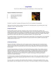
2D plot of Energy versus PSD using an AmBe source at 2<br />
kcounts/s; the two lobes of the neutrons and gammas are<br />
well separated. The data were acquired at Duke University<br />
(TUNL).<br />
<strong>CAEN</strong> Systems & Spectroscopy Division<br />
<strong>CAEN</strong> Systems & Spectroscopy Division is a newborn entity from <strong>CAEN</strong> Electronic<br />
Instrumentation.<br />
In the recent years <strong>CAEN</strong> developed a new digital platform able to meet different nuclear<br />
spectroscopy requirements in a flexible way.<br />
This is the result of several experiences also born from European projects in the field of<br />
radiation monitoring for illicit trafficking of hazardous materials.<br />
Today <strong>CAEN</strong> is looking far ahead and its roadmap includes the development of<br />
instruments not only for research but for real life applications. A new series of instruments<br />
in the field of Environmental Monitoring, Homeland Security and Material Science are<br />
under development and <strong>CAEN</strong> is confident about its capability to provide Top-of-the-<br />
Line Instruments.<br />
<strong>CAEN</strong> is also welcoming all those parties that are willing to cooperate with <strong>CAEN</strong><br />
establishing business relationships for common and mutual benefits. In a changing world<br />
of new paradigms <strong>CAEN</strong> launches its new division.<br />
10 Short Form <strong>Catalog</strong> <strong>2012</strong>
www.caenrfid.it<br />
Compact RFID OEM engine<br />
Overview<br />
<strong>CAEN</strong> RFID is a leading supplier of UHF RFID readers and logger tags. It has been among<br />
the first European companies to design and manufacture UHF RFID readers.<br />
A totally internal expertise and know-how on Radio Frequency electronics and related<br />
Software has allowed <strong>CAEN</strong> RFID to rapidly become a leading European player in the<br />
RFID scenario.<br />
Our EASY2READ © UHF readers are the state-of-the-art for all vertical applications and<br />
allow to use the same identification technology either for proximity or long range reading.<br />
Our EASY2LOG © monitoring tags allow recording of various parameters, such as<br />
temperature and humidity, and are becoming a powerful tool for the monitoring of<br />
temperature sensitive products, such as pharmaceuticals and food.<br />
Thanks to our R&D skills, we can also design specific equipment on a custom basis, thus<br />
providing RFID readers and tags for special applications on demand.<br />
UHF Temperature Logger Tag<br />
Our Vision<br />
Today, the need of identifying, tracking and tracing one’s assets, produce at lower costs<br />
with less waste, guarantee the origin and quality of shipped goods along the supply<br />
chain is becoming a must. UHF RFID technology allows all the above.<br />
USB Desktop Reader<br />
Our Mission<br />
<strong>CAEN</strong> RFID has always tried to understand customers’ needs in their internal processes<br />
and provide the best support for implementing the offered RFID technology.<br />
Besides being a leading supplier of basic RFID technology, <strong>CAEN</strong> RFID is ready to perform<br />
also as a solution enabler, thus allowing to reduce integration time and costs.<br />
Portal RFID Reader<br />
Short Form <strong>Catalog</strong> <strong>2012</strong><br />
11
www.caenels.com<br />
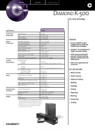
SY3634 - Bipolar Power Supply Heterogeneous System<br />
Overview<br />
<strong>CAEN</strong>els is a young and dynamic company that provides power supplies and measurement<br />
systems (Beam Position Monitoring) for Synchrotron Light Source (SLS) and Free Electron<br />
Laser (FEL) laboratories.<br />
Founded in 2009 as a spin off of <strong>CAEN</strong>, <strong>CAEN</strong>els is strongly customer oriented. Its<br />
business model relies on a close interaction with researchers and electronics engineers<br />
in Science and Applied Physics laboratories all around the world. By analyzing the needs<br />
of the SLS and FEL Community; <strong>CAEN</strong>els can provide complete solutions and electronic<br />
instrumentation for several applications.<br />
Thanks to the technology licensed by Sincrotrone Trieste and the longstanding<br />
engineering, manufacturing and maintenance experience of <strong>CAEN</strong>, <strong>CAEN</strong>els aims to<br />
become a reliable and strategic partner for the SLS and FEL Community, able to integrate<br />
its products and support the Customers with their on-site installations.<br />
AH501 - 4 Channel Bipolar Picoammeter<br />
AH501B - 4 Channel Bipolar Picoammeter with Bias Voltage<br />
12 Short Form <strong>Catalog</strong> <strong>2012</strong>
CAMAC<br />
products<br />
Index<br />
Controllers ...................................................................................... pag. 13<br />
Discriminators ............................................................................... pag. 13<br />
I/O Registers ................................................................................... pag. 14<br />
QDCs ............................................................................................... pag. 14<br />
Scalers ............................................................................................. pag. 15<br />
Controllers<br />
C111C Ethernet CAMAC Crate Controller<br />
The C111C is a CAMAC Crate Controller, housed in a 2-units wide CAMAC module. This device<br />
allows advanced interaction with a CAMAC crate via standard Ethernet services, such as a<br />
local web server and TCP socket based communication protocol. The internal processor<br />
runs a Linux version optimized for low memory footprint. A CAMAC bus control subsection<br />
handles all bus access operations and interactions, including LAM detection; a separate NIM<br />
subsection manages I/O signals located on the front panel: four outputs, four inputs, event<br />
counters and two “COMBO I/O” (TRIGGER/ BUSY) modules. The dynamic local web server,<br />
perfectly suitable for crate setup and maintenance, allows advanced monitoring and control<br />
without the need of any dedicated software installation. An embedded script interpreter<br />
allows the local execution of C-like code, with full control on CAMAC and NIM functions.<br />
Front panel indicators include X and Q signals on last access, four user LEDs (controllable<br />
from script) and fault, connection status and NIM default indicators.<br />
Ordering Information<br />
Code<br />
| Description<br />
WC111CXAAAAA C111C - Ethernet CAMAC Crate Controller<br />
• Full CAMAC bus control with LAM detection<br />
• Full control via embedded dynamic web server<br />
• Available NIM I/O functions: outputs, inputs, event<br />
counters, pulse generators and trigger/busy modules<br />
• Default I/O settings recallable with a dedicated pushbutton<br />
• ANSI C remote control library, with extensions for local<br />
resources control<br />
• Monitoring of crate voltages<br />
• Embedded script interpreter for C-like code local execution,<br />
with CAMAC/NIM functions<br />
• Stored script can be automatically launched at power-up (e.g.<br />
for crate initialization)<br />
• X and Q signals on last access, user LEDs fault, status and NIM<br />
default indicators<br />
Reference Table 16/p. 99<br />
Discriminators<br />
C808 16 Channel Constant Fraction Discriminator<br />
The C808 is a 16 channel Constant Fraction Discriminator,<br />
housed in a 1-unit wide CAMAC module. The module accepts<br />
16 negative inputs and provides 16 differential ECL outputs<br />
with a fan-out of two on front panel header connectors.<br />
Each channel can be turned on or off via CAMAC by using a<br />
mask register (Pattern of Inhibit). The constant fraction delay<br />
is defined by a delay line network of 20 ns with 5 taps. The<br />
pulse forming stage of the discriminator provides an output<br />
pulse with adjustable width in a range from 15 ns to 250<br />
ns. Moreover it is possible to program a dead time interval<br />
during which the discriminator is inhibited from retriggering,<br />
in order to protect against multiple pulsing. The maximum<br />
time walk is ±400 ps (for input signals in the range from -50<br />
mV to -5 V with 25 ns rise time). The constant fraction value<br />
is 20%. The individual discriminating thresholds can be<br />
programmed in a range from -1 mV to -255 mV (-1 mV step)<br />
via CAMAC through an 8-bit DAC. The module can operate<br />
also with small (below 10 mV) input signals, though in this<br />
case the Constant Fraction operation is not performed, i.e.<br />
the time walk is higher. VETO and TEST inputs are available<br />
on the back panel. A CURRENT SUM output provides a current<br />
proportional to the input multiplicity, i.e. to the number of<br />
channels over threshold, at a rate of -1.0 mA ±20% per hit. A<br />
MAJORITY output on a back panel connector provides a NIM<br />
signal if the number of input channels over threshold exceeds<br />
the MAJORITY programmed value. Several C808 boards can<br />
be connected in a daisy chain via the CURRENT SUM output:<br />
in this case, by switching the Majority logic to “External”, it’s<br />
possible to obtain a Majority signal when the number of over<br />
threshold channels in the daisy chained modules exceeds a<br />
global Majority level. An OR output signal on a front panel<br />
connector provides a global OR of the outputs.<br />
• ECL outputs with fan-out of<br />
two<br />
• Individually programmable<br />
threshold for each channel<br />
• Programmable output width<br />
• Programmable dead time<br />
• TEST and VETO inputs<br />
• OR, CURRENT SUM and<br />
MAJORITY outputs<br />
Reference Table 17/p. 99<br />
Ordering Information<br />
Code<br />
| Description<br />
WC808XAAAAAA C808 - 16 Channel Constant Fraction Discriminator (Delay 20 ns; F = 20%)<br />
Short Form <strong>Catalog</strong> 2010<br />
13
CAMAC<br />
Discriminators - continued<br />
C894 16 Channel Leading Edge Discriminator<br />
The C894 is a 16 channel Leading Edge Discriminator,<br />
housed in a 1-unit wide CAMAC module. The module<br />
accepts 16 negative inputs (positive on request)<br />
and provides 16 differential ECL outputs with a fanout<br />
of two on front panel header connectors. The<br />
pulse forming stage of the discriminator produces<br />
an output pulse with adjustable width in a range<br />
from 5 ns to 40 ns. Each channel can operate either<br />
in Updating or Non-Updating mode according to onboard<br />
jumpers position. The discriminator thresholds<br />
are individually programmable in a range from -1 mV<br />
to -255 mV (1 mV step) via CAMAC through an 8-bit<br />
DAC. The minimum detectable signal is -5 mV. VETO<br />
and TEST inputs are available on the back panel. A<br />
CURRENT SUM output provides a current proportional<br />
to the input multiplicity, i. e. to the number of channels<br />
over threshold, at a rate of -1.0 mA per hit ±20%. A<br />
MAJORITY output on a back panel connector provides<br />
a NIM signal if the number of input channels over<br />
threshold exceeds the MAJORITY programmed value.<br />
Several C894 boards can be connected in a daisy<br />
chain via the Current Sum output: in this case, by<br />
switching the Majority logic to External, it’s possible<br />
to obtain a Majority signal when the number of over<br />
threshold channels in the daisy chained modules<br />
exceeds a global Majority level. An OR output on a<br />
front panel connector provides a global OR of the<br />
output channels.<br />
• ECL outputs with fan-out of two<br />
• Selectable Updating/Non Updating mode<br />
• Threshold programmable individually for<br />
each channel<br />
• Programmable output width<br />
• TEST and VETO inputs<br />
• OR, CURRENT SUM and MAJORITY outputs<br />
Reference Table 17/p. 99<br />
Ordering Information<br />
Code<br />
WC894XAAAAAA<br />
| Description<br />
C894 - 16 Channel Leading Edge Discriminator 50 Ohm Negative<br />
I/O Registers<br />
C219<br />
16 Channel Programmable I/O Register<br />
The C219 is a 16 channel Programmable Input/Output<br />
Register, housed in a 1-unit wide CAMAC module.<br />
An internal 16-bit mask register can be programmed<br />
via CAMAC to enable or disable each channel. Each<br />
channel is equipped with a 4-bit status register, which<br />
can be programmed to select the operating mode.<br />
Inputs and Outputs can be enabled either via CAMAC<br />
(Transparent Mode) or by an external STROBE signal<br />
(Externally Strobed Mode).<br />
Each channel can also operate in Glitched Mode; in<br />
this operating mode a positive or negative transition<br />
of an input signal can be stored in the Input Register.<br />
The module features also a programmable LAM signal<br />
generator.<br />
• 16 independent channels programmable as<br />
inputs/outputs<br />
• Inputs: Internally / Externally Strobed or<br />
Glitched<br />
• Outputs: Transparent or Externally Strobed<br />
• Programmable LAM generator<br />
Reference Table 19/p. 99<br />
Ordering Information<br />
Code<br />
WC219XAAAAAA<br />
| Description<br />
C219 - 16 Channel Universal Programmable I/O Register<br />
QDCs<br />
C1205 16 Channel QDC<br />
The C1205 is a 16 channel Charge Integrating ADC,<br />
housed in a 1-unit wide CAMAC. The device combines<br />
a triple range gated integrator charge to voltage<br />
converter (the total dynamic range is greater than 17<br />
bits, in three overlapping 12 bit ranges), 3 Wilkinson<br />
type analog to time converters and a sub nanosecond<br />
time digitizer. The result is a high performance, wide<br />
dynamic range QDC with low dead time (5.5 µs). The<br />
16 inputs are 50 Ohm LEMO type connectors. A CLEAR<br />
input and a BUSY output are also provided. The GATE,<br />
CLEAR and BUSY signals are all NIM levels, with 50 Ohm<br />
LEMO type connectors. The sensitivity at the input<br />
connector ranges from 25 fC per count on the low (most<br />
sensitive) range, to 1.5 pC per count on the high range.<br />
Full scale (on the high range) is greater than 6 nC. The<br />
C1205 has been designed for short conversion time and<br />
maximum data throughput, as required in state-of-theart<br />
physics experiments. The built-in data processing<br />
includes optional sliding scale, pedestal subtraction<br />
and threshold suppression to reduce data volume and<br />
readout time. The module contains a multiple event<br />
buffer that can store up to 51 events. Using FASTCAMAC,<br />
this buffer can be read out at up to 30 MByte/s.<br />
Reference Table 21/p. 100<br />
• Three simultaneous ranges: 80 pC, 650 pC<br />
and 6 nC<br />
• 12 bit resolution<br />
• Total dynamic range larger than 17-bit<br />
• Integral non linearity: ±20 counts on low<br />
range, ±5 counts on high & mid range<br />
• Noise smaller than ±3 counts on low range,<br />
smaller than ±1.5 counts on high & mid<br />
range<br />
• Conversion time: 6.5 µs<br />
• Gate width from 10 to 500 ns<br />
Ordering Information<br />
Code<br />
WC1205XAAAAA<br />
| Description<br />
C1205 - 16 Channel Charge Integrating ADC<br />
14 Short Form <strong>Catalog</strong> 2010 More Technical Specifications available on www.caen.it
Scalers<br />
C257 16 Channel Scaler<br />
The C257 is a 16 channel Scaler, housed in a 1-unit wide<br />
CAMAC module. Each independent channel allows up<br />
to 24 bits counting at a maximum input frequency of<br />
100 MHz. The LAM is asserted by the 16th or 24th bit<br />
(programmable by internal jumpers) for each enabled<br />
channel. The status of the internal jumpers can be read<br />
via CAMAC functions. Each channel can be cascaded<br />
with the following one through internal jumpers. The<br />
unit is available in three different versions accepting<br />
respectively ECL (C257E), NIM (C257N) or TTL (C257T)<br />
inputs.<br />
• 16 independent 24-bit channels<br />
• Cascadeable channels in order to obtain up<br />
to 24x16 bit counting depth<br />
• 100 MHz counting frequency<br />
• Three available versions: ECL, NIM or TTL<br />
inputs<br />
• LAM generation when the counter is full<br />
• Fast Clear, Inhibit and Test NIM inputs<br />
Reference Table 22/p. 100<br />
CAMAC<br />
Ordering Information<br />
Code<br />
| Description<br />
WC257ECLAAAA C257E - 16 Channel Scaler (ECL inputs)<br />
WC257NIMAAAA C257N - 16 Channel Scaler (NIM inputs)<br />
WC257TTLAAAA C257T - 16 Channel Scaler (TTL inputs)<br />
Short Form <strong>Catalog</strong> 2010<br />
15
Desktop<br />
products<br />
Index<br />
Digitizers .................................................................................................... pag. 16<br />
Desktop MCAs ........................................................................................... pag. 17<br />
Power Supply Units High Voltage ........................................................... pag. 17<br />
Preamplifiers Power Supplies ................................................................. pag. 17<br />
Digitizers<br />
DT5720 - DT5720A - DT5720B - DT5720C<br />
• Input range: 2 Vpp with digitally programmable offset<br />
• Bandwidth: 125 MHz.<br />
• Interface: USB 2.0, Optical Link<br />
• Runs Digital Pulse Processing for the Charge Integration (DPP-CI) firmware<br />
• Runs Digital Pulse Processing for Pulse Shape Discrimination (DPP-PSD) firmware<br />
4/2 Channel 12 bit 250 MS/s Digitizers<br />
DPP<br />
CI<br />
DPP<br />
PSD<br />
For more complete information on<br />
<strong>CAEN</strong> Digitizers, see pp. 18-28<br />
Reference Table T9/p. 97<br />
Ordering Information<br />
Code | Description | Input Type | SRAM Memory Sample/ch | AMC FPGA<br />
WDT5720XAAAA DT5720 - 4 Ch. 12 bit 250 MS/s Digitizer: 1.25MS/ch, C4, SE Single ended 1.25 M EP1C4<br />
WDT5720AXAAA DT5720A - 2 Ch. 12 bit 250 MS/s Digitizer: 1.25MS/ch, C4, SE Single ended 1.25 M EP1C4<br />
WDT5720BXAAA DT5720B - 4 Ch. 12 bit 250 MS/s Digitizer: 1.25MS/ch, C20, SE Single ended 1.25 M EP1C20<br />
WDT5720CXAAA DT5720C - 2 Ch. 12 bit 250 MS/s Digitizer: 1.25MS/ch, C20, SE Single ended 1.25 M EP1C20<br />
DT5724 - DT5724A<br />
4/2 Channel 14 bit 100 MS/s Digitizers<br />
• Input range: 2.25 Vpp (10 Vpp and 500 mVpp on request) with digitally programmable offset<br />
• Bandwidth: 40 MHz<br />
• Interface: USB 2.0, Optical Link<br />
• Runs Digital Pulse Processing for Pulse Height Analysis (DPP-PHA) firmware<br />
DPP<br />
PHA<br />
For more complete information on<br />
<strong>CAEN</strong> Digitizers, see pp. 18-28<br />
Reference Table T9/p. 97<br />
Ordering Information<br />
Code | Description | Input Type | SRAM Memory Sample/ch | AMC FPGA<br />
WDT5724XAAAA DT5724 - 4 Ch. 14 bit 100 MS/s Digitizer: 512kS/ch, C4, SE Single ended 512 k EP1C4<br />
WDT5724AXAAA DT5724A - 2 Ch. 14 bit 100 MS/s Digitizer: 512kS/ch, C4, SE Single ended 512 k EP1C4<br />
DT5730 - DT5730A<br />
4/2 Channel 12 bit 500 MS/s Digitizers<br />
• Input range: 2 Vpp with digitally programmable offset<br />
• Bandwidth: 250 MHz<br />
• Interface: USB 2.0, Optical Link<br />
• Runs Digital Pulse Processing for Pulse Shape Discrimination (DPP-PSD) firmware<br />
DT5740 - DT5740C<br />
32 Channel 12 bit 62.5 MS/s Digitizers<br />
• Input range: 2 Vpp/10 Vpp with digitally programmable offset<br />
• Bandwidth: 30 MHz<br />
• Interface: USB 2.0, Optical Link<br />
Ordering Information<br />
DPP<br />
PSD<br />
COMING SOON<br />
For more complete information on<br />
<strong>CAEN</strong> Digitizers, see pp. 18-28<br />
Reference Table T9/p. 97<br />
Code | Description | Input Type | SRAM Memory Sample/ch | AMC FPGA<br />
WDT5740XAAAA DT5740 - 32 Ch. 12 bit 62.5 MS/s Digitizer: 192kS/ch, EP3C16, SE Single ended 192 k EP3C16<br />
WDT5740CXAAA DT5740C - 10Vpp 32 Ch. 12 bit 62.5 MS/s Digitizer: 192kS/ch, EP3C16, SE Single ended 192 k EP3C16<br />
16 Short Form <strong>Catalog</strong> <strong>2012</strong> More Technical Specifications available on www.caen.it
Digitizers - continued<br />
DT5742 - DT5742B<br />
• Based on DRS4 chip Switched capacitor ADC<br />
• Input range: 1 Vpp with digitally programmable offset<br />
• Bandwidth: 600 MHz<br />
• Interface: USB 2.0, Optical Link<br />
16+1 Channel 12 bit 5 GS/s Switched Capacitor Digitizers<br />
For more complete information on<br />
<strong>CAEN</strong> Digitizers, see pp. 18-28<br />
Reference Table T9/p. 97<br />
Ordering Information<br />
Code | Description | Input Type | SRAM Memory Sample/ch | AMC FPGA<br />
WDT5742XAAAA DT5742 - 16+1 Ch. 12 bit 5 GS/s Switched-Capacitor Digitizer: 128 events/ch (1kS/event), EP3C16, SE Single ended 128 events/ch (1kS/event) EP3C16<br />
WDT5742BXAAA DT5742B - 16+1 Ch. 12 bit 5 GS/s Switched-Capacitor Digitizer: 1024 events/ch (1kS/event), EP3C16, SE Single ended 1024 events/ch (1kS/event), EP3C16<br />
DESKTOP<br />
DT5751<br />
2/4 Channel 10 bit 2/1 GS/s Digitizer<br />
• Input range: 1 Vpp with digitally programmable offset<br />
• Bandwidth: 500 MHz<br />
• Interface: USB 2.0, Optical Link<br />
• Runs Digital Pulse Processing for Pulse Shape Discrimination (DPP-PSD) firmware<br />
DPP<br />
PSD<br />
For more complete information on<br />
<strong>CAEN</strong> Digitizers, see pp. 18-28<br />
Reference Table T9/p. 97<br />
Ordering Information<br />
Code | Description | Input Type | SRAM Memory Sample/ch | AMC FPGA<br />
WDT5751XAAAA DT5751 - 2/4 Ch. 10 bit 2/1 GS/s Digitizer: 1.8/3.6 MS/ch, EP3C16, SE Single ended 1.8/3.6 M EP3C16<br />
DT5761<br />
1 Channel 10 bit 4 GS/s Digitizer<br />
• Input range: 1 Vpp with digitally programmable offset<br />
• Bandwidth: 800 MHz<br />
• Interface: USB 2.0, Optical Link<br />
NEW<br />
For more complete information on<br />
<strong>CAEN</strong> Digitizers, see pp. 18-28<br />
Reference Table T9/p. 97<br />
Ordering Information<br />
Code | Description | Input Type | SRAM Memory Sample/ch | AMC FPGA<br />
WDT5761XAAAA DT5761 - 1 Ch. 10 bit 4 GS/s Digitizer: 7.2Ms/ch, EP3C16, SE Single ended 7.2 M EP3C16<br />
Desktop MCAs<br />
DT5780<br />
Digital Multi Channel Analyzer<br />
• Two input Digital MCA based on 14 bit, 100 MS/s digitizers with no<br />
conversion time<br />
• Two ±5 kV, 300 µA HV channels<br />
• Two connectors for preamps and temperature readout<br />
• On line Digital Pulse Processing for Pulse Height Analysis (DPP-<br />
PHA) and time-stamped list mode<br />
• Advanced base line restoration and ballistic deficit correction<br />
• Live correction of Energy spectrum based on advanced pile up<br />
rejection and loss free counting techniques<br />
• Selectable Input dynamic range and adjustable Fine Gain<br />
NEW<br />
For more complete information on<br />
DT5780, see p. 29<br />
Reference Table T20/p. 100<br />
Ordering Information<br />
Code<br />
| Description<br />
WDT5780XPAAA DT5780P - 2 Channel Digital MCA - Positive HV<br />
WDT5780XNAAA DT5780N - 2 Channel Digital MCA - Negative HV<br />
WDT5780XMAAA DT5780M - 2 Channel Digital MCA - Mixed HV<br />
Power Supplies Units High Voltage<br />
NDT1419<br />
NDT1470<br />
NDT1471 - NDT1471H<br />
500 V NIM/Desktop Programmable Power Supply<br />
• 4 channels in 2U NIM/Desktop form factor with 220 V / 110 V<br />
• ±500 V / 200 μA output ranges<br />
• 10 nA Iset/Imon resolution (optional Imon-Zoom: 1 nA)<br />
8 kV NIM/Desktop Programmable Power Supply<br />
• 4 channels in 2U NIM/Desktop form factor with 220 V / 110 V<br />
• ±8 kV / 3mA output ranges Max output power: 9 W (3 kV output)<br />
• 50 nA Iset/Imon resolution (optional Imon-Zoom: 5 nA)<br />
• 4 channels in 2U NIM/Desktop form factor with 220V / 110V<br />
• ±5.5 kV / 300 μA output ranges<br />
• 5 nA Iset/Imon resolution (optional Imon-Zoom: 500 pA)<br />
• High resolution versions also available (20 μA max output, Iset/<br />
Imon: 1nA, optional Imon-Zoom: 50 pA)<br />
• Individually selectable positive or negative polarity<br />
• Local and Remote control (USB/RS485and TCP/IP via <strong>CAEN</strong><br />
NIM8301 crate)<br />
• Individually selectable positive or negative polarity<br />
• Local and Remote control (USB/RS485and TCP/IP via <strong>CAEN</strong><br />
NIM8301 crate)<br />
5.5 kV NIM/Desktop High Accuracy Programmable Power Supplies<br />
• Individually selectable positive or negative polarity<br />
• Local and Remote control (USB/RS485and TCP/IP via <strong>CAEN</strong><br />
NIM8301 crate)<br />
COMING SOON<br />
For more complete information on<br />
NDT1419, see p. 40<br />
Reference Table T1/p. 94<br />
COMING SOON<br />
For more complete information on<br />
NDT1470, see p. 41<br />
Reference Table T1/p. 94<br />
COMING SOON<br />
For more complete information on<br />
NDT1471/H, see p. 42<br />
Reference Table T1/p. 94<br />
Preamplifiers Power Supplies<br />
DT5423 Desktop Linear Power Supply for A1422 - A1423 amplifiers & DT57XX Digitizers COMING SOON<br />
The DT5423 is a desktop power supply for A1422 preamplifiers, DT57XX Digitizers family and<br />
A1423 wideband amplifier. It provides four standard 9-pin “D-type” female connectors to<br />
supply up 4 A1422 preamplifiers. Each output is filtered and fuse protected.<br />
• N.4 DB9 connectors to supply “A1422 family” preamplifiers<br />
• N.1 plug connector to supply “DT57XX family” desktop<br />
digitizers or A1423 wideband amplifier<br />
Short Form <strong>Catalog</strong> <strong>2012</strong><br />
17
Digitizer<br />
products<br />
Index<br />
Introduction ............................................................................................... pag. 19<br />
Principles of Operation ............................................................................. pag. 20<br />
Digital Pulse Processing (DPP) for physics<br />
and biomedical applications ................................................................... pag. 20<br />
Trigger and synchronization in multi-board systems ........................... pag. 22<br />
Software ..................................................................................................... pag. 22<br />
Application ................................................................................................. pag. 23<br />
<strong>CAEN</strong> Waveform Digitizers feature Digital<br />
Pulse Processing (DPP) firmware for physics<br />
applications.<br />
DPP algorithms are implemented in FPGA<br />
and can be reprogrammed at any time. In<br />
one single module you have the complete<br />
information and the capability to extract all<br />
the quantities of interest.<br />
The <strong>CAEN</strong> Digitizers are Platform independent<br />
instruments housing high speed (up to 5 GS/s)<br />
multichannel flash ADC, with local memory and<br />
FPGA for real-time data processing.<br />
Available in different form factors: VME, NIM,<br />
Desktop.<br />
• Up to 14 bit resolution<br />
• VME64X, Optical Link, USB 2.0 Interfaces available<br />
• Memory buffer: up to 58 MS/ch (max. 1024 events)<br />
• Multi-board synchronization and trigger<br />
distribution<br />
• FPGA fimware for Digital Pulse Processing<br />
- Pulse triggering<br />
- Zero suppression<br />
- Pulse Height Analysis<br />
- Charge Integration<br />
- Gamma-Neutron discrimination<br />
- Time measurement<br />
- Possibility of customization<br />
• Software Tools for Windows and Linux<br />
VME NIM Desktop<br />
18 Short Form <strong>Catalog</strong> <strong>2012</strong> More Technical Specifications available on www.caen.it
Introduction<br />
<strong>CAEN</strong> has developed a complete family of digitizers that consists of<br />
several models differing in sampling frequency, resolution, number<br />
of channels, form factor, memory size and other parameters. The<br />
following table lists all models currently available. In parallel with the<br />
hardware development, <strong>CAEN</strong> has made a big effort in developing<br />
algorithms for the Digital Pulse Processing (DPP); you can install a DPP<br />
algorithm on the FPGA of the digitizer (firmware upgrade), run it on-line<br />
and implement new acquisition methods that go beyond the simple<br />
waveform recording. A digitizer with DPP becomes a new instrument<br />
that represents a fully digital replacement of most traditional modules<br />
such as Multi and Single Channel Analyzers, QDCs, TDCs, Discriminators<br />
and many others.<br />
The purpose of the following pages is to provide an overview on the<br />
digitizers, explain the main characteristics and the different operating<br />
modes and present the available options in terms of hardware, firmware<br />
and software in order to guide you in your choice.<br />
DIGITIZERS<br />
Digitizers Selection Table<br />
Model (1) Form Factor N. of ch. (4) Max. Sampling<br />
Frequency (MS/s)<br />
N. of Bits Input Dynamic<br />
Range (Vpp) (4) Single Ended /<br />
Differential Input<br />
Bandwidth<br />
(MHz)<br />
Memory (MS/ch) (4) DPP firmware (5)<br />
x724<br />
VME 8<br />
SE / D<br />
100 14 0.5 / 2.25 / 10<br />
Desktop/NIM 4 / 2<br />
SE<br />
40 0.5 / 4 PHA<br />
x720<br />
VME 8<br />
SE / D<br />
250 12 2<br />
Desktop/NIM 4 / 2<br />
SE<br />
125 1.25 / 10 CI, PSD<br />
x721 VME 8 500 8 1 SE / D 250 2 no<br />
x731 VME 8 - 4 500 - 1000 8 1 SE / D 250 / 500 2 / 4 no<br />
x730<br />
VME 8<br />
SE / D<br />
500 12 2<br />
Desktop/NIM 4 / 2 SE<br />
250 1.25 / 10 PSD<br />
x751<br />
VME 8 - 4<br />
SE / D<br />
1000 - 2000 10 1<br />
Desktop/NIM 4 - 2<br />
SE<br />
500 1.8 / 14.4 - 3.6 / 28.8 PSD<br />
x761<br />
VME 2<br />
SE / D<br />
4000 10 1<br />
Desktop/NIM 1<br />
SE<br />
TBD 7.2 / 57.6 no<br />
x740<br />
VME 64<br />
Desktop/NIM 32<br />
62.5 12 2 / 10 SE 30 0.19 / 1.5 no<br />
x742<br />
VME 32+2<br />
Desktop/NIM 16+1<br />
5000 (2) 12 1 SE 600 0.128 / 1 (3) no<br />
All models<br />
Analog Input<br />
Trigger<br />
Synchronization<br />
Memory<br />
FPGA<br />
Readout<br />
Other features<br />
Single Ended: MCX 50 Ω; Differential (where present): MODU-II 110 Ω<br />
DC offset adjust in the full range (±FSR/2)<br />
Positive, negative and bipolar inputs<br />
External TRG-IN, Software or channel self-trigger<br />
Common (all models/firmware) or Individual (DPP only)<br />
TRG-OUT for trigger propagation<br />
Digital timing and trigger filters for pulse triggering (DPP only)<br />
32 bit Time Stamp<br />
Daisy Chain (VME only) or one-to-many clock distribution<br />
Clock Cable delay compensation<br />
Sync start/stop through S-IN or GPI input or Trigger In/Out<br />
External Time Stamp reset<br />
up to 1024 acquisition buffers (2)<br />
Independent read/write access<br />
Ability to do on-line Digital Pulse Processing (DPP) for pulse shaping and height analysis, digital charge<br />
integration, gamma-neutron discrimination, timing, segmented detectors, etc…<br />
USB (30MB/s), CONET (80MB/S), VME (60MB/s MBLT, 120MB/s 2eSST)<br />
Independent read/write access<br />
16 programmable LVDS GPIOs (VME only)<br />
Analog Output for monitors, sum of the inputs, multiplicity, test waveform, etc… (VME only)<br />
(1) The x in the model name is V1 for VME, VX1 for VME64X, DT5 for Desktop and N6 for NIM<br />
(2) Sampling frequency of the analog memory (switched capacitor array); A/D conversion takes<br />
place at lower speed (dead-time)<br />
(3) The memory size for the x742 is 128/1024 events of 1024 samples each<br />
(4) The indication “size 1/ size 2” denotes different options<br />
(5) DPP-PHA: Pulse Height Analysis (Trapezoidal Filters), DPP-CI: Charge Integration (digital<br />
QDC), DPP-PSD: Pulse Shape Discrimination<br />
Short Form <strong>Catalog</strong> <strong>2012</strong><br />
19
DIGITIZERS<br />
Principles of Operation<br />
The basic operating mode of a digitizer is essentially the same as a digital oscilloscope:<br />
the analog signal, after an input stage of signal conditioning mainly used to adapt<br />
the dynamic range, is sampled by a flash ADC, whose output, i.e. the stream of digital<br />
samples, is continuously read by an FPGA and stored in a circular memory buffer of a<br />
programmable size. At the arrival of the trigger, the buffer is frozen and made available<br />
for the readout while the acquisition can continue in a new buffer.<br />
However, there are few important differences between a digitizer and a commercial<br />
digital oscilloscope:<br />
1. The digitizers allow for dead-timeless acquisition.<br />
In fact, unlike most oscilloscopes, they have the ability to accept two<br />
consecutive triggers very close to each other (1) thanks to the multi buffer<br />
memory management: there is no dead time between an acquisition window<br />
and the next one. It is even possible to accept two trigger for which the<br />
acquisition windows overlap. The dead-timeless acquisition is a very important<br />
feature, especially in the case of events randomly distributed in time (in nuclear<br />
physics this is typically a Poissonian distribution), so that two of them, even at<br />
low rate, can occur at very short distance but you still want to capture both.<br />
(1) Except for 742 Series.<br />
2. In the digitizers, all the channels are allowed to generate triggers independently.<br />
The individual trigger can be used locally by the channel that generated it (independent triggering) or can participate to the assertion of a global<br />
trigger for all the channels in the board, as well as to generate a pulse on the TRG-OUT.<br />
3. The digitizers are designed for scalability.<br />
It is possible to synchronize several boards to make an acquisition system with a theoretically unlimited number of channels. Board synchronization<br />
consists of distributing a common clock reference on which all the ADC sampling clock are locked, aligning the acquisition time base of each board<br />
in order to have events with correlated time stamps, distributing the channel auto-triggers and the global triggers according to a programmable<br />
trigger logic in order to implement coincidences, neighbour triggering and other acquisition criteria and topologies.<br />
4. The High bandwidth data readout links.<br />
Usually oscilloscopes do not have any communication channel (data is only displayed) or, if they have, most probably it has a fairly low bandwidth<br />
(GPIB, Ethernet, etc…); conversely, the digitizers are designed to provide high rate data transfer to a computer or an external data processing unit.<br />
<strong>CAEN</strong> digitizers have a minimum bandwidth of ~30MB/s in the case of the USB, about 80MB/s with CONET port up to more than 120MB/s for the<br />
VME with 2eSST.<br />
5. On Line data processing.<br />
The acquisition in the digitizers is based on FPGAs. These are programmable<br />
devices with the ability to manage the ADC sample stream and implement<br />
on-line digital algorithms for signal processing. This feature is of fundamental<br />
importance for the implementation of systems that are not simply based on<br />
the acquisition, storage and readout of waveforms (raw data) but rather on<br />
the calculation of certain quantities of interest (e.g. the charge associated with<br />
a pulse, the pulse height, the leading edge, the baseline, the arrival time and<br />
other parameters) and the storage and transfer of just the final results, with clear<br />
advantages in terms of readout bandwidth.<br />
• Dead-timeless acquisition<br />
• Individual pulse self-trigger<br />
• Multi-board synchronization for system<br />
scalability<br />
• High bandwidth data readout links<br />
• On-line data processing (FPGA or DSP) DPP<br />
<strong>CAEN</strong> Digitizer block diagram:<br />
• The mother board defines the form-factor; it contains one FPGA for the<br />
readout interfaces and the services<br />
• The daughter board defines the type of digitizer; it contains the input<br />
amplifiers, the ADCs, the FPGA for the data processing and the memories<br />
Digital Pulse Processing (DPP) for physics and biomedical applications<br />
In recent years, thanks to the availability on the market of faster and more precise ADC chips, applications in the field of nuclear physics (or related<br />
fields) have made large use of data acquisition systems based on digitizers. Compared to the traditional analog acquisition systems, in which the A/D<br />
conversion is performed at the end of the chain, the new systems have reversed that approach: the conversion to digital is performed as close as<br />
possible to the source of the signal (output of the detector or preamplifier).<br />
However, systems based on digitizers have a basic fundamental problem: the extremely huge amount of data to manage. As stated above, high<br />
trigger rate, multitude of channels and high readout<br />
bandwidth are the features that characterize the • One single board can do the job of several analog modules<br />
digitizers when compared to the digital oscilloscope; at • Full information preserved<br />
the same time, these features lead to large data streams.<br />
For this reason it is important to have an FPGA with the • Reduction in size, cabling, power consumption and cost per channel<br />
ability to do on-line data processing and to extract from • High reliability and reproducibility<br />
the raw samples sequence only the specific parameters<br />
necessary to the acquisition.<br />
• Flexibility (different digital algorithms can be designed and loaded<br />
at any time into the same hardware)<br />
20 Short Form <strong>Catalog</strong> <strong>2012</strong><br />
More Technical Specifications available on www.caen.it
For this purpose, special algorithms<br />
can be applied to the digital<br />
samples coming from the ADC for<br />
the extraction of the quantities of<br />
interest and the reduction of the<br />
data; the relevant digital filters are,<br />
in most cases, very similar (at least<br />
from a functional point of view) to<br />
the old and familiar analog circuits,<br />
such as timing filters, shapers,<br />
CFDs, baseline restorers, etc..<br />
DIGITIZERS<br />
The benefits of the digital approach are great stability and reproducibility, ability to reprogram and tailor the algorithms to the application,<br />
ability to preserve the information of the signal along the entire acquisition chain, better correction of unwanted effect such as baseline<br />
fluctuation, pile-up, ballistic deficit, etc… All this in one board.<br />
To better understand the principles of operation of the DPP, let’s take a practical example: suppose you have a detector for spectroscopy (scintillator<br />
and phototube) which generates pulses with a duration of about 100 ns. We can utilize an algorithm that permits you to extract the pulse charge on-line<br />
in the FPGA of the digitizer (i.e. continuously and in real time); to do this, we need to calculate the baseline by means of a moving average filter, detect<br />
the pulses when<br />
the signal exceeds<br />
a certain threshold<br />
respect to the<br />
baseline (trigger),<br />
60 Co gamma spectrum acquired with a HPGe and DPP-PHA at University of Palermo. In the box, a least squares fit<br />
of the 1.33 MeV photopeak; a FWHM < 2 keV was obtained.<br />
implement a digital<br />
delay line in order<br />
to compensate the<br />
trigger latency and<br />
finally sum a certain<br />
number of samples within the integration gate<br />
after having subtracted the baseline from them.<br />
The charge thus obtained, together with a time<br />
stamp that identifies the position of the pulse, is<br />
the only information stored in memory for that<br />
event, resulting in a significant reduction of the<br />
data, such as 8 bytes per event, instead of saving<br />
the portion of the waveform that contains the<br />
pulse and a piece of baseline, which could consist<br />
of tens or hundreds of samples.<br />
2D plot of Energy versus PSD using an AmBe source at 2 kcounts/s; the two lobes of the neutrons and gammas are<br />
well separated. The data were acquired at DukeUniversity (TUNL).<br />
<strong>CAEN</strong> is willing to collaborate with customers to<br />
create other types of firmware and algorithms<br />
for specific applications.<br />
In this example the algorithm replaces in<br />
digital form the same acquisition chain which<br />
traditionally consisted of a discriminator, a QDC<br />
and an analog delay line to fit the pulse within<br />
the gate coming from the discriminator. Other<br />
examples of algorithms implemented on <strong>CAEN</strong>’s<br />
digitizer (generically called DPP, or Digital Pulse<br />
Processing) are those for<br />
(1) Pulse Height Analysis using trapezoidal<br />
filters, algorithms for the gamma-neutron<br />
discrimination realized by means of Pulse<br />
Shape Analysis, Zero suppression (removal of<br />
parts of signal that do not contain pertinent<br />
information),<br />
(2) Implementation of digital timing filter or<br />
digital constant fraction discriminator to<br />
determine precise timing information,<br />
(3) Mixed acquisition modes in which the quantities of interest calculated by the DPP<br />
(charge, height, etc ...) are saved together with a short but significant chunk of<br />
waveform (e.g. the rising edge) to allow for off-line analysis, etc..<br />
The digitizers are available with the standard version of the firmware that implement only the waveform acquisition mode (oscilloscope mode) or,<br />
in certain cases, some techniques of zero suppression. The firmware that implements a certain DPP algorithm is provided separately as an ordering<br />
option. The user can download any of this DPP from our Web site, install it on the digitizer that supports it and try it for free, with the only limitation<br />
that the acquisition may not last more than 30 minutes, after which you must perform a power-cycle (Time Bomb). Only after purchasing each<br />
Short Form <strong>Catalog</strong> <strong>2012</strong><br />
21
DIGITIZERS<br />
firmware and its relevant license (that is installed on the card in the form of electronic key) the time bomb will be eliminated. The table below shows<br />
all types of DPP and the relevant digitizers that support them. For more detailed information on the DPP algorithms and firmware, please refer to the<br />
White Paper WP2081.<br />
Name Model Detectors (typ.) Notes<br />
DPP-PHA x724 Hi res. SI, Ge Digital Pulse Processing for Pulse Height Analysis<br />
DPP-CI x720 PMT, SiPM Digital Pulse Processing for Charge Integration<br />
DPP-PSD x720, x751 Organic liquid Digital Pulse Processing for Pulse Shape Discrimination<br />
NEW<br />
Trigger and synchronization in multi-board systems<br />
In most cases, the applications that require the use of several channels, need to synchronize the acquisition across different digitizers, this is performed<br />
according to the following points:<br />
1. Distribution of a common clock reference in order to have the same sampling clock on all the ADC channels. <strong>CAEN</strong>’s digitizers feature a<br />
programmable PLL able to generate the sampling clocks locked to an external clock input (usually at lower frequency) whose distribution can be<br />
done in parallel from a common source, using a fan-out, as well as through an in-out daisy chain with the ability to use the first board as a clock<br />
master and to compensate for delays in the cables by means of a programmable phase shift. The daisy-chain mode is available only in the VME<br />
models.<br />
2. Alignment of the time stamp associated with the triggers to allow off-line reconstruction of the events read from different boards. This can be<br />
done by using a dedicated SYNC input as well as through the TRG-IN, TRG-OUT daisy chain by issuing a first pulse acting as a start of acquisition;<br />
this pulse doesn’t trigger the channels. After that, the TRG-IN and TRG-OUT start their normal operating mode that is to receive and send triggers.<br />
3. Distribution of the triggers from channel to channel and from board to board, according to a certain trigger logic. Each card has different sources<br />
of trigger: external TRG-IN from the front panel, software trigger and channel self-triggers. All these triggers can be combined in order to make<br />
coincidences, majorities, global triggers and other functions. It is worth noticing that the DPP firmware, compared to the standard version, gives<br />
important advantages also in terms of trigger managing: first of all, the digital filters are able to detect the input pulses and generate triggers even in<br />
the presence of noise, baseline fluctuation and pile-up that make inefficient the simple trigger mechanism based on a fixed threshold. Furthermore,<br />
with the DPP, the channels operate independently and it is possible to implement the trigger propagation on a channel to channel basis, also<br />
including channels on different boards. This option is particularly useful in the segmented detectors where the detection of one pulse in a certain<br />
segment requires the acquisition of the signals also in the neighbour segments in order to calculate the exact position in which the particle hit.<br />
Software<br />
<strong>CAEN</strong> provides drivers for all the different types of physical communication channels (USB 2.0 or the proprietary CONET Optical Link, managed by<br />
the A2818 PCI card or A3818 PCIe cards or the VME bus accessed by the V1718 and V2718 bridges), a set of C and LabView libraries, demo applications<br />
and utilities. Windows and Linux are both supported.<br />
More specifically, the available software is the following:<br />
<strong>CAEN</strong>Comm library<br />
Contains the basic functions for access to hardware; the aim of this<br />
library is to provide a unique interface to the higher layers regardless<br />
the type of physical communication channel. Note: for VME access,<br />
<strong>CAEN</strong>comm is based on <strong>CAEN</strong>’s VME bridges V1718 (USB to VME) and<br />
V2718 (PCI to VME). In the case of third-part bridges or SBCs, the user<br />
must provide the functions contained in the <strong>CAEN</strong>comm library for to<br />
the relevant platform.<br />
<strong>CAEN</strong>Digitizer library<br />
Contains the functions to program the digitizers, manage the<br />
acquisition, execute the readout, unpack the data, send triggers, etc...<br />
WaveDump<br />
It’s a Console application that lets you program the digitizer (according to a text<br />
configuration file that contains a list of parameters and instructions), to start the<br />
acquisition, read the data, display the readout and trigger rate, apply some post<br />
processing (such as FFT and amplitude histogram), save data to a file and also plot the<br />
waveforms using the external plotting tool “gnuplot” that is available on internet for<br />
free. This program is quite basic and has no graphics but it is an excellent example of C<br />
code that demonstrates the use of libraries and methods for an efficient readout and<br />
data analysis. It is strongly recommended, to any user willing to write the SW on their<br />
own to start with this demo and modify it according to his or her needs.<br />
For more details please see the WaveDump User Manual (UM2091) and Quick Start Guide (GD2084 ).<br />
22 Short Form <strong>Catalog</strong> <strong>2012</strong><br />
More Technical Specifications available on www.caen.it
<strong>CAEN</strong>Scope<br />
It’s a fully graphical program that implements a simple<br />
oscilloscope: you can see the waveforms, set the trigger<br />
thresholds, change the scales of time and amplitude, perform<br />
simple mathematical operations between the channels, save<br />
data to file and other operations. <strong>CAEN</strong>scope is provided as an<br />
executable file; the source codes are not distributed.<br />
DIGITIZERS<br />
NOTE: <strong>CAEN</strong>Scope does not work with digitizers running DPP<br />
firmware.<br />
For more details please see the <strong>CAEN</strong>Scope Quick Start Guide GD2484.<br />
<strong>CAEN</strong>Upgrader<br />
It’s a tool that allows the user to update the firmware of the digitizers, change<br />
the PLL settings (i.e. set the ADC sampling frequency, enable the clock output,<br />
etc...), load, when requested, the license for the pay firmware (for example, the<br />
DPP-CI, DPP-PHA and DPP-PSD) and other utilities.<br />
For more details please see the <strong>CAEN</strong>Upgrader Quick Start Guide GD2512.<br />
DPP Control Software<br />
It’s an application that manages the acquisition in<br />
the digitizers which have DPP firmware installed on<br />
it. The program consist of different parts: there is a<br />
GUI whose purpose is to set all the parameters for<br />
the DPP and for the acquisition; the GUI generates<br />
a textual configuration file that contains all the<br />
parameters. This file is read by the Acquisition<br />
Engine, which is a C console application that<br />
programs the digitizer according to the parameters,<br />
starts the acquisition and manage the data readout.<br />
The data, that can be waveforms, time stamps,<br />
energies or other quantities of interest, can be<br />
saved to output files or plotted using “gnuplot” as<br />
an external plotting tool, exactly like in WaveDump.<br />
Name Software Notes<br />
DPP-PHA DPP-PHA Control Software works only with x724 models and DPP-PHA<br />
DPP-CI DPP-CI Control Software works only with x720 models and DPP-CI<br />
DPP-PSD DPP-PSD Control Software works only with x720 OR X751 models and DPP-PSD<br />
Application<br />
The great versatility of the DPP algorithms allowed <strong>CAEN</strong> to develop a new product dedicated to the gamma spectrometry, the DT5780 Digital MCA.<br />
This module is a compact, stand-alone digital solution for Pulse Height Analysis based on DPP-PHA firmware.<br />
It houses a two-channel, 14-bit, 100 MS / s digitizer (see Model DT5724A), two HV channels able to supply a bias voltage up to + -5 kV, 300 µA and two<br />
connectors for the power supply of preamplifiers and detector temperature readout.<br />
For more information about DT5780, please refer to page 29.<br />
Short Form <strong>Catalog</strong> <strong>2012</strong><br />
23
DIGITIZERS<br />
Model<br />
Ordering<br />
Code<br />
Description<br />
Single<br />
Ended /<br />
Differential<br />
Input<br />
SRAM<br />
Memory<br />
Sample/ch<br />
AMC<br />
FPGA (*)<br />
X724 WDT5724XAAAA DT5724 - 4 Ch. 14 bit 100 MS/s Digitizer: 512kS/ch, C4, SE SE 512 k EP1C4 Desktop<br />
WDT5724AXAAA DT5724A - 2 Ch. 14 bit 100 MS/s Digitizer: 512kS/c h, C4, SE SE 512 k EP1C4 Desktop<br />
WN6724XAAAAA N6724 - 4 Ch. 14 bit 100 MS/s Digitizer: 512kS/ch, C4, SE SE 512 k EP1C4 NIM<br />
WN6724AXAAAA N6724A - 2 Ch. 14 bit 100 MS/s Digitizer: 512kS/ch , C4, SE SE 512 k EP1C4 NIM<br />
WV1724XAAAAA V1724 - 8 Ch. 14 bit 100 MS/s Digitizer: 512kS/ch, C4, SE SE 512 k EP1C4 6U-VME64<br />
WV1724BXAAAA V1724B - 8 Ch. 14 bit 100 MS/s Digitizer: 4MS/ch, C4, SE SE 4 M EP1C4 6U-VME64<br />
WV1724CXAAAA V1724C - 8 Ch. 14 bit 100 MS/s Digitizer: 512kS/ch, C4, DIFF DIFF 512 k EP1C4 6U-VME64<br />
WV1724DXAAAA V1724D - 8 Ch. 14 bit 100 MS/s Digitizer: 4MS/ch, C4, DIFF DIFF 4 M EP1C4 6U-VME64<br />
WV1724EXAAAA V1724E - 8 Ch. 14 bit 100 MS/s Digitizer: 4MS/ch, C20, SE SE 4 M EP1C20 6U-VME64<br />
WV1724FXAAAA V1724F - 8 Ch. 14 bit 100 MS/s Digitizer: 4MS/ch, C20, DIFF DIFF 4 M EP1C20 6U-VME64<br />
WV1724GXAAAA V1724G - 8 Ch. 14 bit 100 MS/s Digitizer: 512KS/ch , C20, SE SE 512 k EP1C20 6U-VME64<br />
WVX1724XAAAA VX1724 - 8 Ch. 14 bit 100 MS/s Digitizer: 512kS/ch, C4, SE SE 512 k EP1C4 6U-VME64X<br />
WVX1724BXAAA VX1724B - 8 Ch. 14 bit 100 MS/s Digitizer: 4MS/ch, C4, SE SE 4 M EP1C4 6U-VME64X<br />
WVX1724CXAAA VX1724C - 8 Ch. 14 bit 100 MS/s Digitizer: 512kS/ch, C4, DIFF DIFF 512 k EP1C4 6U-VME64X<br />
WVX1724DXAAA VX1724D - 8 Ch. 14 bit 100 MS/s Digitizer: 4MS/ch, C4, DIFF DIFF 4 M EP1C4 6U-VME64X<br />
WVX1724EXAAA VX1724E - 8 Ch. 14 bit 100 MS/s Digitizer: 4MS/ch, C20, SE SE 4 M EP1C20 6U-VME64X<br />
WVX1724FXAAA VX1724F - 8 Ch. 14 bit 100 MS/s Digitizer: 4MS/ch, C20, DIFF DIFF 4 M EP1C20 6U-VME64X<br />
X720 WDT5720XAAAA DT5720 - 4 Ch. 12 bit 250 MS/s Digitizer: 1.25MS/ch, C4, SE SE 1.25 M EP1C4 Desktop<br />
WDT5720AXAAA DT5720A - 2 Ch. 12 bit 250 MS/s Digitizer: 1.25MS/ ch, C4, SE SE 1.25M EP1C4 Desktop<br />
WDT5720BXAAA DT5720B - 4 Ch. 12 bit 250 MS/s Digitizer: 1.25MS/ch, C20, SE SE 1.25 M EP1C20 Desktop<br />
WDT5720CXAAA DT5720C - 2 Ch. 12 bit 250 MS/s Digitizer: 1.25MS/ch, C20, SE SE 1.25 M EP1C20 Desktop<br />
WN6720XAAAAA N6720 - 4 Ch. 12 bit 250 MS/s Digitizer: 1.25MS/ch, C4, SE SE 1.25 M EP1C4 NIM<br />
WN6720AXAAAA N6720A - 2 Ch. 12 bit 250 MS/s Digitizer: 1.25MS/c h, C4, SE SE 1.25M EP1C4 NIM<br />
WN6720BXAAAA N6720B - 4 Ch. 12 bit 250 MS/s Digitizer: 1.25MS/ch, C20, SE SE 1.25 M EP1C20 NIM<br />
WN6720CXAAAA N6720C - 2 Ch. 12 bit 250 MS/s Digitizer: 1.25MS/ch, C20, SE SE 1.25 M EP1C20 NIM<br />
WV1720XAAAAA V1720 - 8 Ch. 12 bit 250 MS/s Digitizer: 1.25MS/ch, C4, SE SE 1.25 M EP1C4 6U-VME64<br />
WV1720BXAAAA V1720B - 8 Ch. 12 bit 250 MS/s Digitizer: 10MS/ch, C4, SE SE 10 M EP1C4 6U-VME64<br />
WV1720CXAAAA V1720C - 8 Ch. 12 bit 250 MS/s Digitizer: 1.25MS/ch, C4, DIFF DIFF 1.25 M EP1C4 6U-VME64<br />
WV1720DXAAAA V1720D - 8 Ch. 12 bit 250 MS/s Digitizer: 10MS/ch, C4, DIFF DIFF 10 M EP1C4 6U-VME64<br />
WV1720EXAAAA V1720E - 8 Ch. 12 bit 250 MS/s Digitizer: 1.25MS/ch, C20, SE SE 1.25 M EP1C20 6U-VME64<br />
WV1720FXAAAA V1720F - 8 Ch. 12 bit 250 MS/s Digitizer: 1.25MS/ch, C20, DIFF DIFF 1.25 M EP1C20 6U-VME64<br />
WVX1720XAAAA VX1720 - 8 Ch. 12 bit 250 MS/s Digitizer: 1.25MS/ch, C4, SE SE 1.25 M EP1C4 6U-VME64X<br />
WVX1720BXAAA VX1720B - 8 Ch. 12 bit 250 MS/s Digitizer: 10MS/ch, C4, SE SE 10 M EP1C4 6U-VME64X<br />
WVX1720CXAAA VX1720C - 8 Ch. 12 bit 250 MS/s Digitizer: 1.25MS/ch, C4, DIFF DIFF 1.25 M EP1C4 6U-VME64X<br />
WVX1720DXAAA VX1720D - 8 Ch. 12 bit 250 MS/s Digitizer: 10MS/ch, C4, DIFF DIFF 10 M EP1C4 6U-VME64X<br />
WVX1720EXAAA VX1720E - 8 Ch. 12 bit 250 MS/s Digitizer: 1.25MS/ch, C20, SE SE 1.25 M EP1C20 6U-VME64X<br />
WVX1720FXAAA VX1720F - 8 Ch. 12 bit 250 MS/s Digitizer: 1.25MS /ch, C20, DIFF DIFF 1.25 M EP1C20 6U-VME64X<br />
X721 WV1721BXAAAA WV1721XAAAAA V1721 - 8 Ch. 8 bit 500 MS/s Digitizer: 2MS/ch, C4, SE SE 2 M EP1C4 6U-VME64<br />
WV1721XAAAAA WV1721BXAAAA V1721B - 8 Ch. 8 bit 500 MS/s Digitizer: 2MS/ch, C4, DIFF DIFF 2 M EP1C4 6U-VME64<br />
WVX1721XAAAA WVX1721XAAAA VX1721 - 8 Ch. 8 bit 500 MS/s Digitizer: 2MS/ch, C4, SE SE 2 M EP1C4 6U-VME64X<br />
WVX1721BXAAA WVX1721BXAAA VX1721B - 8 Ch. 8 bit 500 MS/s Digitizer: 2MS/ch, C4, DIFF DIFF 2 M EP1C4 6U-VME64X<br />
X730 WDT5730AXAAA WDT5730XAAAA DT5730 - 4 Ch. 12 bit 500 MS/s Digitizer: 1.25MS/ch, EP3C16, SE COMING SOON SE 1.25 M EP3C16 Desktop<br />
WDT5730XAAAA WDT5730AXAAA DT5730A - 2 Ch. 12 bit 500 MS/s Digitizer: 1.25MS/ch, EP3C16, SE COMING SOON SE 1.25 M EP3C16 Desktop<br />
WN6730AXAAAA WN6730XAAAAA N6730 - 4 Ch. 12 bit 500 MS/s Digitizer: 1.25MS/ch, EP3C16, SE COMING SOON SE 1.25 M EP3C16 NIM<br />
WN6730XAAAAA WN6730AXAAAA N6730A - 2 Ch. 12 bit 500 MS/s Digitizer: 1.25MS/ch, EP3C16, SE COMING SOON SE 1.25 M EP3C16 NIM<br />
WV1730BXAAAA WV1730XAAAAA V1730 - 8 Ch. 12 bit 500 MS/s Digitizer: 1.25MS/ch, EP3C16, SE COMING SOON SE 1.25 M EP3C16 6U-VME64<br />
WV1730XAAAAA WV1730BXAAAA V1730B - 8 Ch. 12 bit 500 MS/s Digitizer: 10MS/ch, EP3C16, SE COMING SOON SE 10 M EP3C16 6U-VME64<br />
WVX1730BXAAA WVX1730XAAAA VX1730 - 8 Ch. 12 bit 500 MS/s Digitizer: 1.25MS/ch, EP3C16, SE COMING SOON SE 1.25 M EP3C16 6U-VME64X<br />
WVX1730XAAAA WVX1730BXAAA VX1730B - 8 Ch. 12 bit 500 MS/s Digitizer: 10MS/ch, EP3C16, SE COMING SOON SE 10 M EP3C16 6U-VME64X<br />
X731 WV1731XAAAAA V1731 - 4/8 Ch. 8 bit 1000/500 MS/s Digitizer: 4/2MS/ch, C4, SE SE 2/4 M EP1C4 6U-VME64<br />
WV1731BXAAAA V1731B - 4/8 Ch. 8 bit 1000/500 MS/s Digitizer: 4/2MS/ch, C4, DIFF DIFF 2/4 M EP1C4 6U-VME64<br />
WVX1731XAAAA VX1731 - 4/8 Ch. 8 bit 1000/500 MS/s Digitizer: 4/2MS/ch, C4, SE SE 2/4 M EP1C4 6U-VME64X<br />
WVX1731BXAAA VX1731B - 4/8 Ch. 8 bit 1000/500 MS/s Digitizer: 4/2MS/ch, C4, DIFF DIFF 2/4 M EP1C4 6U-VME64X<br />
X740 WDT5740XAAAA DT5740 - 32 Ch. 12 bit 62.5 MS/s Digitizer: 192kS/ch, EP3C16, SE SE 192 k EP3C16 Desktop<br />
WDT5740CXAAA DT5740C - 10Vpp 32 Ch. 12 bit 62.5 MS/s Digitizer: 192kS/ch, EP3C16, SE SE 192 k EP3C16 Desktop<br />
WN6740XAAAAA N6740 - 32 Ch. 12 bit 62.5 MS/s Digitizer: 192kS/ch, EP3C16, SE SE 192 k EP3C16 NIM<br />
WN6740CXAAAA N6740C - 10Vpp 32 Ch. 12 bit 62.5 MS/s Digitizer: 192kS/ch, EP3C16, SE SE 192 k EP3C16 NIM<br />
WV1740XAAAAA V1740 - 64 Ch. 12 bit 62.5 MS/s Digitizer: 192kS/ch, EP3C16, SE SE 192 k EP3C16 6U-VME64<br />
WV1740AXAAAA V1740A - 10Vpp input 64ch 12bit 62.5MS/s Digitizer: 1.5 MS/ch, EP3C16, SE SE 1.5 M EP3C16 6U-VME64<br />
WV1740BXAAAA V1740B - 64 Ch. 12 bit 62.5 MS/s Digitizer: 1.5 MS/ch, EP3C16, SE SE 1.5 M EP3C16 6U-VME64<br />
WV1740CXAAAA V1740C - 10Vpp input 64ch 12bit 62.5MS/s Digitizer: 192kS/ch, EP3C16, SE SE 192 k EP3C16 6U-VME64<br />
WVX1740XAAAA VX1740 - 64 Ch. 12 bit 62.5 MS/s Digitizer: 192kS/ch, EP3C16, SE SE 192 k EP3C16 6U-VME64X<br />
WVX1740AXAAA VX1740A - 10Vppm 64 Ch. 12 bit 62.5 MS/s Digitizer: 1.5 MS/ch, EP3C16, SE SE 1.5 M EP3C16 6U-VME64X<br />
WVX1740BXAAA VX1740B - 64 Ch. 12 bit 62.5 MS/s Digitizer: 1.5 MS/ch, EP3C16, SE SE 1.5 M EP3C16 6U-VME64X<br />
WVX1740CXAAA VX1740C - 10Vppm 64 Ch. 12 bit 62.5 MS/s Digitizer: 192 KS/ch, EP3C16, SE SE 192 k EP3C16 6U-VME64X<br />
(*) AMC: ADC & Memory controller FPGA. ALTERA models available: EP1C4: Cyclone (4.000 LEs), EP1C20: Cyclone (20.000 LEs), EP3C16: Cyclone III (16.000 LEs).<br />
Form<br />
factor<br />
24 Short Form <strong>Catalog</strong> <strong>2012</strong><br />
More Technical Specifications available on www.caen.it
Model<br />
Ordering<br />
Code<br />
Description<br />
Single<br />
Ended /<br />
Differential<br />
Input<br />
SRAM<br />
Memory<br />
Sample/ch<br />
AMC<br />
FPGA (*)<br />
X761 WDT5761XAAAA DT5761 - 1Ch.10 bit 4 GS/s Digitizer: 7.2MS/ch, EP3C16, SE NEW SE 7.2 M EP3C16 Desktop<br />
WN6761XAAAAA N6761 - 1 Ch. 10 bit 4 GS/s Digitizer: 7.2Ms/ch, EP3C16, SE NEW SE 7.2 M EP3C16 NIM<br />
WV1761XAAAAA V1761 - 2Ch.10 bit 4 GS/s Digitizer: 7.2MS/ch, EP3C16, SE NEW SE 7.2 M EP3C16 6U-VME64<br />
WV1761BXAAAA V1761B - 2Ch.10 bit 4 GS/s Digitizer: 7.2MS/ch, EP3C16, DIFF NEW DIFF 7.2 M EP3C16 6U-VME64<br />
WV1761CXAAAA V1761C - 2 Ch. 10 bit 4 GS/s Digitizer: 57.6MS/ch, EP3C16, SE NEW SE 57.6 M EP3C16 6U-VME64<br />
WVX1761CXAAA VX1761 - 2Ch.10 bit 4 GS/s Digitizer: 7.2MS/ch, EP3C16, SE NEW SE 7.2 M EP3C16 6U-VME64X<br />
WVX1761BXAAA VX1761B - 2Ch.10 bit 4 GS/s Digitizer: 7.2MS/ch, EP3C16, DIFF NEW DIFF 7.2 M EP3C16 6U-VME64X<br />
WVX1761CXAAA VX1761C - 2 Ch. 10 bit 4 GS/s Digitizer: 57.6MS/ch, EP3C16, SE NEW SE 57.6 M EP3C16 6U-VME64X<br />
X751 WDT5751XAAAA DT5751 - 2/4 Ch. 10 bit 2/1 GS/s Digitizer: 1.8/3.6MS/ch, EP3C16, SE SE 1.8/3.6 M EP3C16 Desktop<br />
WN6751XAAAAA N6751 - 2/4 Ch. 10 bit 2/1 GS/s Digitizer: 1.8/3.6MS/ch, EP3C16, SE SE 1.8/3.6 M EP3C16 NIM<br />
WV1751XAAAAA V1751 - 4/8 Ch. 10 bit 2/1 GS/s Digitizer: 1.8/3.6MS/ch, EP3C16, SE SE 1.8/3.6 M EP3C16 6U-VME64<br />
WV1751BXAAAA V1751B - 4/8 Ch. 10 bit 2/1 GS/s Digitizer: 1.8/3.6MS/ch, EP3C16, DIFF DIFF 1.8/3.6 M EP3C16 6U-VME64<br />
WV1751CXAAAA V1751C - 4/8 Ch. 10 bit 2/1 GS/s Digitizer: 14.4/2 8.8MS/ch, EP3C16, SE SE 14.4/28.8M EP3C16 6U-VME64<br />
WVX1751XAAAA VX1751 - 4/8 Ch. 10 bit 2/1 GS/s Digitizer: 1.8/3.6MS/ch, EP3C16, SE SE 1.8/3.6 M EP3C16 6U-VME64X<br />
WVX1751BXAAA VX1751B - 4/8 Ch. 10 bit 2/1 GS/s Digitizer: 1.8/3.6MS/ch, EP3C16, DIFF DIFF 1.8/3.6 M EP3C16 6U-VME64X<br />
WVX1751CXAAA VX1751C - 4/8 Ch. 10 bit 2/1 GS/s Digitizer: 14.4/ 28.8MS/ch, EP3C16, SE SE 14.4/28.8M EP3C16 6U-VME64X<br />
X742 WDT5742XAAAA DT5742 - 16+1 Ch. 12 bit 5 GS/s Switched-Capacitor Digitizer: 128kS/ch, EP3C16, SE SE 128 k EP3C16 Desktop<br />
WDT5742BXAAA DT5742B - 16+1 Ch. 12 bit 5 GS/s Switched-Capacito r Digitizer: 1024 events/ch (1kS/event), EP3C16, SE SE 1 M EP3C16 Desktop<br />
WN6742XAAAAA N6742 - 16+1 Ch. 12 bit 5 GS/s Switched-Capacitor Digitizer: 128kS/ch, EP3C16, SE SE 128 k EP3C16 NIM<br />
WN6742BXAAAA N6742B - 16+1 Ch. 12 bit 5 GS/s Switched-Capacitor Digitizer: 1024 events/ch (1kS/event), EP3C16, SE SE 1 M EP3C16 NIM<br />
WV1742XAAAAA V1742 - 32+2 Ch. 12 bit 5 GS/s Switched-Capacitor Digitizer: 128kS/ch, EP3C16, SE SE 128 k EP3C16 6U-VME64<br />
WV1742BXAAAA V1742B - 32+2 Ch. 12 bit 5 GS/s Switched-Capacitor Digitizer: 1024 events/ch (1kS/events), EP3C16, SE SE 1 M EP3C16 6U-VME64<br />
WVX1742XAAAA VX1742 - 32+2 Ch. 12 bit 5 GS/s Switched-Capacitor Digitizer: 128kS/ch, EP3C16, SE SE 128 k EP3C16 6U-VME64X<br />
(*) AMC: ADC & Memory controller FPGA. ALTERA models available: EP1C4: Cyclone (4.000 LEs), EP1C20: Cyclone (20.000 LEs), EP3C16: Cyclone III (16.000 LEs).<br />
WVX1742BXAAA VX1742B - 32+2 Ch. 12 bit 5GS/s Switched-Capacitor Digitizer: 1024 events/ch (1kS/event), EP3C16, SE SE 1 M EP3C16 6U-VME64X<br />
(*) AMC: ADC & Memory controller FPGA. ALTERA models available: EP1C4: Cyclone (4.000 LEs), EP1C20: Cyclone (20.000 LEs), EP3C16: Cyclone III (16.000 LEs).<br />
Form<br />
factor<br />
DIGITIZERS<br />
Accessories • Ordering Information<br />
Code<br />
| Description<br />
WA2818XAAAAA<br />
A2818 - PCI Optical Link Controller<br />
WA3818AXAAAA<br />
A3818 - PCIe 1 Optical Link<br />
WA3818BXAAAA<br />
A3818 - PCIe 2 Optical Link<br />
WA3818CXAAAA<br />
A3818 - PCIe 4 Optical Link<br />
WAI2703XAAAA<br />
AI2703 - Optical Fibre 30cm. simplex<br />
WAI2705XAAAA<br />
AI2705 - Optical Fibre 5 m. simplex<br />
WAI2720XAAAA<br />
AI2720 - Optical Fibre 20 m. simplex<br />
WAI2730XAAAA<br />
AI2730 - Optical Fibre 30 m. simplex<br />
WAI2740XAAAA<br />
AI2740 - Optical Fibre 40 m. simplex<br />
WAY2705XAAAA<br />
AY2705 - Optical Fibre 5 m. duplex<br />
WAY2720XAAAA<br />
AY2720 - Optical Fibre 20 m. duplex<br />
WAY2730XAAAA<br />
AY2730 - Optical Fibre 30 m. duplex<br />
WA654XAAAAAA<br />
A654 - Single Channel MCX to LEMO Cable Adapter<br />
WA654K4AAAAA<br />
A654 KIT4 - 4 MCX TO LEMO Cable Adapter<br />
WA654K8AAAAA<br />
A654 KIT8 - 8 MCX TO LEMO Cable Adapter<br />
WA659XAAAAAA<br />
A659 - Single Channel MCX to BNC Cable Adapter<br />
WA659K4AAAAA<br />
A659 KIT4 - 4 MCX TO BNC Cable Adapter<br />
WA659K8AAAAA<br />
A659 KIT8 - 8 MCX TO BNC Cable Adapter<br />
WA746BXAAAAA<br />
A746B - 64Ch.Adapter for LEMO connector<br />
WA746DXAAAAA<br />
A746D - 32 Ch.Adapter for Lemo connector<br />
WA746EXAAAAA<br />
A746E - 32 Ch. Adapter for Lemo connector<br />
Customizations<br />
Code<br />
WPERS0172401<br />
WPERS0172402<br />
WPERS0175101<br />
| Description<br />
V1724 Customization - 10Vpp Input Range, SE<br />
V1724 Customization - 500mVpp Input Range, SE<br />
V1751 Customization - 10Vpp Input Range<br />
Short Form <strong>Catalog</strong> <strong>2012</strong><br />
25
Firmware for DPP (Digital Pulse Processing)<br />
Index<br />
DPP-PHA Digital Pulse Processing for Pulse Height Analisys ............ pag. 26<br />
DPP-CI Digital Pulse Processing for Charge Integration ....................... pag. 27<br />
DPP-PSD Digital Pulse Processing for Pulse Shape Discrimination .... pag. 28<br />
DPP-PHA Digital Pulse Processing for Pulse Height Analysis<br />
• Digital solution equivalent to shaping<br />
amplifier + peak sensing ADC (Multi-<br />
Channel Analyzer)<br />
• Implemented in the 724 digitizer family (14<br />
bit @ 100 MS/s)<br />
• The digitizer is directly connected to the<br />
charge sensitive preamplifier<br />
• Programmable input offset, trigger and<br />
energy filter parameters<br />
• Better correction of pile-up and ballistic<br />
deficit<br />
• Higher counting rate (live time)<br />
• Provides also timing information (pulse time<br />
stamps and/or rise/fall time)<br />
<strong>CAEN</strong> Waveform Digitizers feature firmware for Digital Pulse Processing (DPP) for physics<br />
applications.<br />
The purpose of the DPP is to perform online signal processing on detector signals directly digitized,<br />
able to transform the raw sequence of samples into a compressed data packet that preserves the<br />
information required, minimizing the event data size. DPP algorithms are implemented in FPGA and<br />
can be reprogrammed at any time. In one single module you have the complete information and the<br />
capability to extract all the quantities of interest.<br />
The 724 digitizers running DPP-PHA firmware can perform as multichannel data acquisition systems<br />
for nuclear physics or other applications requiring radiation detection.<br />
The digitizers accept signals directly from Charge Sensitive Preamplifiers or photomultiplier and<br />
implement a digital replacement of Shaping Amplifier and Peak Sensing ADC (Multi-Channel<br />
Analyzer).<br />
The digitizer runs on real time:<br />
• Self Trigger using CR-RC-CR digital algorithm<br />
• Trapezoidal filter for Pulse Height Analysis and Energy spectra<br />
• Digital Constant Fraction Discriminator for event time measurement<br />
Some typical applications:<br />
• Gamma ray spectroscopy with Germanium and Silicon Detectors<br />
• Readout of PMTs with slow scintillators (for instance NaI)<br />
• Applications that require a moderate timing resolution to perform coincidences<br />
DPP-PHA Control Software<br />
DPP-PHA Control Software is a demo program that allows the user to<br />
understand the principle of operation of the Digital Pulse Processing (DPP)<br />
and to manage the acquisition of signals acquired and read out from the<br />
digitizers (<strong>CAEN</strong> series 724 14 bit, 100MS/s digitizer). Using this tool, the user<br />
can easily set all the parameters of the Digital Pulse Processing, configure the<br />
digitizer, run the acquisition, readout the data and plot or save the results in<br />
form of waveforms (like an oscilloscope) as well as energy and time stamp<br />
histograms or lists.<br />
DPP-PHA Supported Boards<br />
• DT5724 - 4 Channel 14 bit 100 MS/s Digitizer - Desktop module<br />
• DT5724A - 2 Channel 14 bit 100 MS/s Digitizers - Desktop module<br />
• N6724 - 4 Channel 14 bit 100 MS/s Digitizer - NIM module<br />
• N6724A - 2 Channel 14 bit 100 MS/s Digitizer - NIM module<br />
• V1724 - 8 Channel 14 bit 100 MS/s Digitizer - VME 6U module<br />
• VX1724 - 8 Channel 14 bit 100 MS/s Digitizer - VME64X 6U module<br />
Free downloadable DPP-PHA Trial version.<br />
• The User can download the Trial version for evaluation<br />
• The Trial version has a DAQ time frame limitation: every 30 min the user<br />
has to restart (power off/power on) the board<br />
• To get full functionality the user should purchase a License and register it<br />
• The procedure is automatic and can be completed on our web site<br />
Ordering Information<br />
Code<br />
| Description<br />
WFWDPPTFAAAA DPP-PHA - Digital Pulse Processing for Pulse Heigh Analysis (x724)<br />
WFWDPPTF02AA DPP-PHA - Digital Pulse Processing for Pulse Heigh Analysis (x724) - 2 Licence Pack<br />
WFWDPPTF05AA DPP-PHA - Digital Pulse Processing for Pulse Heigh Analysis (x724) - 5 Licence Pack<br />
WFWDPPTF10AA DPP-PHA - Digital Pulse Processing for Pulse Heigh Analysis (x724) - 10 Licence Pack<br />
WFWDPPTF20AA DPP-PHA - Digital Pulse Processing for Pulse Heigh Analysis (x724) - 20 Licence Pack<br />
26 Short Form <strong>Catalog</strong> <strong>2012</strong> More Technical Specifications available on www.caen.it
DPP-CI<br />
Digital Pulse Processing for the Charge Integration<br />
• Digital solution equivalent to QDC +<br />
discriminator + gate generator<br />
• Implemented in the 720 digitizer family (12<br />
bit @ 250 MS/s)<br />
• Self Gating (no discriminator) with digital<br />
noise filtering<br />
• No delay line is needed to fit the position of<br />
the pulse inside the gate<br />
• Programmable Gate width and position<br />
• Charge integration with automatic Baseline<br />
subtraction (pedestal)<br />
• Dead-timeless acquisition (no conversion<br />
time)<br />
• Extremely high dynamic range<br />
• On-line coincidences between couples of<br />
channels<br />
• Provides also timing information (pulse time<br />
stamps)<br />
• Free Trial version download<br />
DPP<br />
<strong>CAEN</strong> Waveform Digitizers feature firmware for Digital Pulse Processing (DPP) for physics<br />
applications. The purpose of the DPP is to perform online signal processing on detector signals directly<br />
digitized, able to transform the raw sequence of samples into a compressed data packet that preserves<br />
the information required, minimizing the event data size. DPP algorithms are implemented in FPGA<br />
and can be reprogrammed at any time. In one single module you have the complete information and<br />
the capability to extract all the quantities of interest.<br />
The 720 digitizers running DPP-CI firmware can perform as multichannel data acquisition systems<br />
for nuclear physics or other applications requiring radiation detection.<br />
The digitizers accept signals directly from the detector and implement a digital replacement of QDC,<br />
discriminator and gate generator.<br />
The digitizer runs on real time:<br />
• Self Trigger using CR-RC digital Time filter algorithm<br />
• Input signal baseline (pedestal) calculation<br />
• Charge Integration (with programmable gate parameters) with pedestal subtraction for energy<br />
calculation<br />
Some typical applications:<br />
• Readout of PMTs with fast and slow scintillators<br />
• Readout of SiPM (single photon counting)<br />
• Applications that require a moderate timing resolution to perform coincidences<br />
DPP-CI Control Software<br />
DPP-CI Control Software is a demo program that allows the user to<br />
understand the principle of operation of the Digital Pulse Processing (DPP)<br />
and to manage the acquisition of signals acquired and read out from the<br />
digitizers (<strong>CAEN</strong> series 720 12 bit, 250MS/s digitizer). Using the DPP-CI<br />
Control Software, the user can easily set all the parameters of the Digital Pulse<br />
Processing, configure the digitizer, run the acquisition, readout the data and<br />
plot or save the results in form of waveforms (like an oscilloscope) as well as<br />
energy and time stamp histograms or lists.<br />
DPP-CI Supported Boards<br />
• DT5720 / DT5720B - 4 Channel 12 bit 250 MS/s Digitizer - Desktop<br />
modules<br />
• DT5720A / DT5720C - 2 Channel 12 bit 250 MS/s Digitizer - Desktop<br />
modules<br />
• N6720 / N6720B - 4 Channel 12 bit 250 MS/s Digitizer - NIM modules<br />
• N6720A / N6720C - 2 Channel 12 bit 250 MS/s Digitizer - NIM modules<br />
• V1720 - 8 Channel 12 bit 250 MS/s Digitizer - VME 6U module<br />
• VX1720 - 8 Channel 12 bit 250 MS/s Digitizer - VME64X 6U module<br />
Free downloadable DPP-CI Trial version.<br />
• The User can download the Trial version for evaluation<br />
• The Trial version has a DAQ time frame limitation: every 30 min the user<br />
has to restart (power off/power on) the board<br />
• To get full functionality the user should purchase a License and register it<br />
• The procedure is automatic and can be completed on our web site<br />
Ordering Information<br />
Code<br />
| Description<br />
WFWDPPCIAAAA DPP-CI Digital Pulse Processing for Charge Integration (x720)<br />
WFWDPPCI02AA DPP-CI Digital Pulse Processing for Charge Integration (x720) - 2 Licence Pack<br />
WFWDPPCI05AA DPP-CI Digital Pulse Processing for Charge Integration (x720) - 5 Licence Pack<br />
WFWDPPCI10AA DPP-CI Digital Pulse Processing for Charge Integration (x720) - 10 Licence Pack<br />
WFWDPPCI20AA DPP-CI Digital Pulse Processing for Charge Integration (x720) - 20 Licence Pack<br />
Short Form <strong>Catalog</strong> <strong>2012</strong><br />
27
DPP<br />
DPP-PSD<br />
Digital Pulse Processing for Pulse Shape Discrimination<br />
NEW<br />
• Digital solution equivalent to dual gate QDC<br />
+ discriminator + gate generator<br />
• Implemented in the 720 & 751 digitizer<br />
families (12 bit @ 250 MS/s & 10 bit @ 1/2<br />
GS/s)<br />
• Double charge integration for Pulse Shape<br />
Discrimination<br />
• Programmable width and position of the<br />
two gates<br />
• Self Gating (no discriminator) with digital<br />
noise filtering<br />
• No delay line is needed to fit the position of<br />
the pulse inside the two gates<br />
• Automatic Baseline subtraction (pedestal)<br />
• Dead-timeless acquisition (no conversion<br />
time)<br />
• Extremely high dynamic range<br />
• On-line coincidences between couples of<br />
channels<br />
• Provides also timing information (pulse time<br />
stamps)<br />
• Free Trial version download<br />
<strong>CAEN</strong> Waveform Digitizers feature firmware for Digital Pulse Processing (DPP) for physics<br />
applications. The purpose of the DPP is to perform online signal processing on detector signals directly<br />
digitized, able to transform the raw sequence of samples into a compressed data packet that preserves<br />
the information required, minimizing the event data size. DPP algorithms are implemented in FPGA<br />
and can be reprogrammed at any time. In one single module you have the complete information and<br />
the capability to extract all the quantities of interest.<br />
The 720 1 and 751 digitizers running DPP-PSD firmware can perform as multichannel data acquisition<br />
systems for nuclear physics or other applications requiring radiation detection.<br />
The digitizers accept signals directly from the detector and implement a digital replacement of dual<br />
gate QDC, discriminator and gate generator.<br />
The digitizer runs on real time:<br />
• Self Trigger using CR-RC digital Time filter algorithm<br />
• Input signal baseline (pedestal) calculation<br />
• Dual gate generation with programmable parameters<br />
• Double integration of the prompt and delayed charge for Pulse Shape Discrimination<br />
• Pedestal subtraction for energy calculation<br />
Some typical applications:<br />
• Readout of PMTs coupled to organic liquid scintillators (e.g. BC501-A)<br />
• Applications that require a moderate timing resolution to perform coincidences<br />
• Gamma-Neutron discrimination (dual gate integration)<br />
(1) DPP-PSD runs only on 720 digitizers equipped with EP1C20 AMC FPGA<br />
DPP-PSD Control Software<br />
DPP-PSD Control Software is a program that allows the user to understand<br />
the principle of operation of the Digital Pulse Processing (DPP) and to<br />
manage the acquisition of signals acquired and read out from the digitizers.<br />
Using this tool, the user can easily set all the parameters of the Digital Pulse<br />
Processing, configure the digitizers, run the acquisition, readout the data and<br />
plot or save the results in form of waveforms (like an oscilloscope) as well as<br />
energy and time tag histograms or lists.<br />
DPP-PSD Supported Boards<br />
• DT5720B 1 - 4 Channel 12 bit 250 MS/s Digitizer - Desktop module<br />
• DT5720C 1 - 2 Channel 12 bit 250 MS/s Digitizer - Desktop module<br />
• N6720B 1 - 4 Channel 12 bit 250 MS/s Digitizer - NIM module<br />
• N6720C 1 - 2 Channel 12 bit 250 MS/s Digitizer - NIM module<br />
• V1720 1 - 8 Channel 12 bit 250 MS/s Digitizer - VME 6U module<br />
• VX1720 1 - 8 Channel 12 bit 250 MS/s Digitizer - VME64X 6U module<br />
• DT5751- 2/4 Channel 10 bit 2/1 GS/s Digitizer - Desktop module<br />
• N6751- 2/4 Channel 10 bit 2/1 GS/s Digitizer - NIM module<br />
• V1751- 4/8 Channel 10 bit 2/1 GS/s Digitizer - VME 6U module<br />
• VX1751- 4/8 Channel 10 bit 2/1 GS/s Digitizer - VME64X 6U module<br />
Free downloadable DPP-PSD Trial version.<br />
• The User can download the Trial version for evaluation<br />
• The Trial version has a DAQ time frame limitation: every 30 min the user<br />
has to restart (power off/power on) the board<br />
• To get full functionality the user should purchase a License and register it<br />
• The procedure is automatic and can be completed on our web site<br />
Ordering Information<br />
Code<br />
| Description<br />
WFWDPPNGAA20 DPP-PSD - Digital Pulse Processing for Pulse Shape Discrimination (x720)<br />
WFWDPPNG0220 DPP-PSD - Digital Pulse Processing for Pulse Shape Discrimination (x720) - 2 Licence Pack<br />
WFWDPPNG0520 DPP-PSD - Digital Pulse Processing for Pulse Shape Discrimination (x720) - 5 Licence Pack<br />
WFWDPPNG1020 DPP-PSD - Digital Pulse Processing for Pulse Shape Discrimination (x720) - 10 Licence Pack<br />
WFWDPPNG2020 DPP-PSD - Digital Pulse Processing for Pulse Shape Discrimination (x720) - 20 Licence Pack<br />
WFWDPPNGAA51 DPP-PSD - Digital Pulse Processing for Pulse Shape Discrimination (x751)<br />
WFWDPPNG0251 DPP-PSD - Digital Pulse Processing for Pulse Shape Discrimination (x751) - 2 Licence Pack<br />
WFWDPPNG0551 DPP-PSD - Digital Pulse Processing for Pulse Shape Discrimination (x751) - 5 Licence Pack<br />
WFWDPPNG1051 DPP-PSD - Digital Pulse Processing for Pulse Shape Discrimination (x751) - 10 Licence Pack<br />
WFWDPPNG2051 DPP-PSD - Digital Pulse Processing for Pulse Shape Discrimination (x751)- 20 Licence Pack<br />
NEW<br />
NEW<br />
NEW<br />
NEW<br />
NEW<br />
NEW<br />
NEW<br />
NEW<br />
NEW<br />
NEW<br />
28 Short Form <strong>Catalog</strong> <strong>2012</strong><br />
More Technical Specifications available on www.caen.it
DT5780<br />
Digital Multi Channel Analyzer<br />
NEW<br />
The DT5780 is a complete digital system for X and Gamma ray spectroscopy.<br />
A compact, stand alone digital MCA houses a two channel, 14 bit, 100 MS/s digitizer<br />
(see Mod. DT5724A), two HV channels able to supply a bias voltage up to ±5 kV, 300 uA<br />
and two connectors for the power supply of preamplifiers and detector temperature<br />
readout.<br />
A cost effective and compact spectroscopy<br />
solution featuring <strong>CAEN</strong> HV, digitizer and<br />
digital Pulse Height Analysis.<br />
DT5780 relies on<br />
DPP-PHA, a dedicated<br />
firmware developed for<br />
Pulse Height Analysis.<br />
DPP-PHA performs an<br />
advanced on line Digital Pulse Processing allowing an effective data analysis even at<br />
high count rate, taking in account baseline restoration, ballistic deficit correction, pileup<br />
rejection and live correction of the Energy spectrum, allowing quantitative analysis<br />
even for sources with unsteady activities.<br />
Thanks to the two channels simultaneous acquisition, the module is able to manage<br />
coincidence and anti coincidence between a pair of detectors, allowing the user,<br />
for example, to easily take advantage of background rejection or anti-Compton<br />
techniques.<br />
The module is designed with sinchronization capabilities, allowing the customer to<br />
easily build multiboard systems.<br />
• Two input Digital MCA based on<br />
14 bit, 100 MS/s digitizers with no<br />
conversion time<br />
• On line Digital Pulse Processing for<br />
Pulse Height Analysis (PHA) and<br />
time-stamped list mode<br />
• Waveform recording for custom off<br />
line analysis to match application<br />
requirements<br />
• Two HV channels to bias detectors up<br />
to ± 5 kV, 300 µA<br />
• Two Preamp power connectors<br />
with ± 12 V, ± 24 V and temperature<br />
readout<br />
• Advanced base line restoration and<br />
ballistic deficit correction<br />
• Live correction of Energy spectrum<br />
based on advanced pile up rejection<br />
and loss free counting techniques<br />
• Selectable Input dynamic range and<br />
adjustable Fine Gain<br />
• Multiple trace analog and digital<br />
oscilloscope for an easy setup and<br />
signal monitoring<br />
• Windows and Linux, 32 and 64 bit OS<br />
supported<br />
• C/C++ and LabVIEW libraries for<br />
an easy interface to custom DAQ<br />
systems<br />
• USB and Optical Link communication<br />
interfaces<br />
Ordering Information<br />
Code<br />
| Description<br />
WDT5780XPAAA DT5780P - 2 Channel Digital MCA - Positive HV<br />
WDT5780XNAAA DT5780N - 2 Channel Digital MCA - Negative HV<br />
WDT5780XMAAA DT5780M - 2 Channel Digital MCA - Mixed HV<br />
Short Form <strong>Catalog</strong> <strong>2012</strong><br />
29
NIM<br />
products<br />
Index<br />
ADCs (Peak Sensing) • Multi Channel Analyzers ..................................... pag. 30<br />
Digitizers • Multi Channel Analyzers ....................................................... pag. 30<br />
Digitizers ................................................................................................... pag. 31<br />
Analog Pulse Processors ......................................................................... pag. 32<br />
Amplifiers (Fast) ....................................................................................... pag. 32<br />
Amplifiers (Spectroscopy) ...................................................................... pag. 33<br />
Attenuators ............................................................................................... pag. 34<br />
Coincidence/Logic/Trigger Units ........................................................... pag. 34<br />
Discriminators ........................................................................................... pag. 35<br />
Fan In - Fan Out Units ................................................................................ pag. 36<br />
Scalers ........................................................................................................ pag. 36<br />
Timing Units .............................................................................................. pag. 36<br />
Translators ................................................................................................. pag. 37<br />
Power Supply Units High Voltage ............................................................ pag. 37<br />
Power Supply Units Low Voltage ............................................................. pag. 38<br />
ADCs (Peak Sensing) • Multi Channel Analyzers<br />
N957<br />
8k Multi-Channel Analyzer<br />
The N957 is an 8k Multi-Channel Analyzer (MCA) with<br />
an USB port, housed in a 1-unit wide NIM module. The<br />
MCA performs the function of collecting the input<br />
signals and producing an output, in the form of the<br />
converted values of the input signals’ peaks. The<br />
input pulses can be the ones produced by a standard<br />
spectroscopy amplifier’s output. They can be Gaussian,<br />
semi-Gaussian or square waves, unipolar (positive)<br />
or bipolar, in a range from 0 to 10 V, with a rise time<br />
greater than 0.1 µs. The trigger can be either “on<br />
signal” (Auto Gate mode) or “external” (External Gate<br />
mode). In the first case a discriminator, with a settable<br />
threshold, enables the conversion. In the second<br />
case, an external gate is fed to the module via a front<br />
panel GATE connector. The input channel has a peak<br />
amplitude stretcher, whose output is digitised by a 13-<br />
bit ADC featuring a sliding scale technique, to improve<br />
the differential non-linearity. Converted waveforms<br />
are stored into a 64 kSamples buffer memory. The unit<br />
hosts an USB2.0 port, which allows a simple control<br />
and data-acquisition via PC.<br />
Libraries for Windows and Linux are available.<br />
Firmware upgrade can be performed via USB.<br />
• Single input Multi-Channel Analyzer<br />
• Fully computer controlled MCA<br />
• 8k ADC, fast conversion time with<br />
linearization enhancement circuit<br />
• PHA acquisition mode<br />
• Suitable for HPGe, Nai(Tl), CdTe and other<br />
detector types<br />
• USB 2.0 communication interface<br />
• Libraries, Demos (C and LabView) and<br />
Software tools for Windows and Linux<br />
Reference Table 20/p. 100 - 8/p. 97<br />
Ordering Information<br />
Code<br />
| Description<br />
WN957XAAAAAA N957 - 8K Multi-Channel Analyzer<br />
Digitizers • Multi Channel Analyzers<br />
N1728A – N1728B<br />
The N1728 is a 4-channel Digital Pulse Processor and Waveform Digitizer,<br />
housed in a 1-unit wide NIM module. The N1728 operates in “Oscilloscope”<br />
mode, continuously storing waveforms (10 ms wide buffer with pre-trigger<br />
capability) and can be set also in “Energy” mode, thus providing, together<br />
with scope function, a real time trapezoidal shaping, with a wide range of<br />
programmable filter parameters, and energy measurement. A dedicated<br />
digital trigger algorithm allows very low energy threshold operation, thus<br />
ensuring immunity to noise effects. A digital Constant Fraction Discriminator<br />
(CFD) has been implemented for applications requiring accurate timing.<br />
4 Channel 14 bit 100 MS/s Digitizer with Pulse Shape Analysis<br />
Ordering Information<br />
Code<br />
| Description<br />
WN1728XAAAAA N1728A - 4 Ch.14 bit 100 MS/s Digitizer with Pulse Shape Analysis (Differential inputs)<br />
WN1728XBAAAA N1728B - 4 Ch. 14 bit 100 MS/s Digitizer with Pulse Shape Analysis (Single Ended Inputs)<br />
• 14 bit 100 MS/s ADC<br />
• Differential (N1728A) or Single Ended (N1728B) input signals<br />
• “Oscilloscope” mode/transient recorder with 10 ms wide<br />
waveform buffer<br />
• “Energy” mode with real time trapezoidal shaping for energy<br />
determination and time stamp<br />
• Digital trigger and Constant Fraction Discriminator<br />
• Base Line Restoration and pile-up rejection<br />
• Two circular memory buffers (512 ksamples)<br />
• Two analog TEST output signals via 12 bit / 100 MHz DAC<br />
(Monitor Output A1÷A2)<br />
• External or internal clock<br />
• Firmware upgradeable via USB2.0<br />
• Software for full module control and data readout via USB2.0<br />
Reference Table 20/p. 100 - 9/p. 97<br />
30 Short Form <strong>Catalog</strong> <strong>2012</strong> More Technical Specifications available on www.caen.it
Digitizers<br />
The <strong>CAEN</strong> Digitizers available in NIM form factor are listed here below.<br />
<strong>CAEN</strong> Digitizers are platform independent instruments housing high speed (up to 5 GS/s) multichannel ADC, with local memory and<br />
FPGA for real‐time data processing. Available in different form factors: VME, NIM and Desktop. For more complete information see<br />
pages 18-28. General Digitizer Reference Table: T9/p. 97.<br />
NIM<br />
N6720 - N6720A - N6720B - N6720C 4/2 Channel 12 bit 250 MS/s Digitizers<br />
• Input range: 2 Vpp with digitally programmable offset<br />
• Bandwidth: 125 MHz.<br />
• Interface: USB 2.0, Optical Link<br />
• Runs Digital Pulse Processing for the Charge Integration (DPP-CI) firmware<br />
• Runs Digital Pulse Processing for Pulse Shape Discrimination (DPP-PSD) firmware<br />
Ordering Information<br />
For more complete information on<br />
<strong>CAEN</strong> Digitizers, see pp. 18-28<br />
Reference Table T9/p. 97<br />
Code | Description | Input Type | SRAM Memory Sample/ch | AMC FPGA<br />
WN6720XAAAAA N6720 - 4 Ch. 12 bit 250 MS/s Digitizer: 1.25MS/ch, C4, SE Single ended 1.25 M EP1C4<br />
WN6720AXAAAA N6720A - 2 Ch. 12 bit 250 MS/s Digitizer: 1.25MS/c h, C4, SE Single ended 1.25 M EP1C4<br />
WN6720BXAAAA N6720B - 4 Ch. 12 bit 250 MS/s Digitizer: 1.25MS/c h, C20, SE Single ended 1.25 M EP1C20<br />
WN6720CXAAAA N6720C - 2 Ch. 12 bit 250 MS/s Digitizer: 1.25MS/c h, C20, SE Single ended 1.25 M EP1C20<br />
DPP<br />
CI<br />
DPP<br />
PSD<br />
N6724 - N6724A<br />
4/2 Channel 14 bit 100 MS/s Digitizers<br />
For more complete information on<br />
<strong>CAEN</strong> Digitizers, see pp. 18-28<br />
• Input range: 2.25 Vpp (10 Vpp and 500 mVpp on request) with digitally programmable offset<br />
Reference Table T9/p. 97<br />
• Bandwidth: 40 MHz<br />
DPP<br />
• Interface: USB 2.0, Optical Link<br />
PHA<br />
• Runs Digital Pulse Processing for Pulse Height Analysis (DPP-PHA) firmware<br />
Ordering Information<br />
Code | Description | Input Type | SRAM Memory Sample/ch | AMC FPGA<br />
WN6724XAAAAA N6724 - 4 Ch. 14 bit 100 MS/s Digitizer: 512kS/ch, C4, SE Single ended 512 k EP1C4<br />
WN6724AXAAAA N6724A - 2 Ch. 14 bit 100 MS/s Digitizer: 512kS/ch, C4, SE Single ended 512 k EP1C4<br />
N6730 - N6730A<br />
4/2 Channel 12 bit 500 MS/s Digitizer<br />
• Input range: 2 Vpp with digitally programmable offset<br />
• Bandwidth: 250 MHz<br />
• Runs Digital Pulse Processing for Pulse Shape Discrimination (DPP-PSD) firmware<br />
DPP<br />
PSD<br />
COMING SOON<br />
N6740 - N6740C 32 Channel 12 bit 62.5 MS/s Digitizers<br />
• Input range: 2 Vpp/10 Vpp with digitally programmable offset<br />
• Bandwidth: 30 MHz<br />
• Interface: USB 2.0, Optical Link<br />
Ordering Information<br />
Code | Description | Input Type | SRAM Memory Sample/ch | AMC FPGA<br />
WN6740XAAAAA N6740 - 32 Ch. 12 bit 62.5 MS/s Digitizer: 192kS/ch, EP3C16, SE Single ended 192 k EP3C16<br />
WN6740CXAAAA N6740C - 10Vpp 32 Ch. 12 bit 62.5 MS/s Digitizer: 192kS/ch, EP3C16, SE Single ended 192 k EP3C16<br />
N6742 - N6742B<br />
16+1 Channel 12 bit 5 GS/s Switched Capacitor Digitizers<br />
For more complete information on<br />
<strong>CAEN</strong> Digitizers, see pp. 18-28<br />
• Based on DRS4 chip Switched capacitor ADC<br />
Reference Table T9/p. 97<br />
• Input range: 1 Vpp with digitally programmable offset<br />
• Bandwidth: 600 MHz<br />
• Interface: USB 2.0, Optical Link<br />
Ordering Information<br />
Code | Description | Input Type | SRAM Memory Sample/ch | AMC FPGA<br />
WN6742XAAAAA N6742 - 16+1 Ch. 12 bit 5 GS/s Switched-Capacitor Digitizer: 128 events/ch (1kS/event), EP3C16, SE Single ended 128 events/ch (1kS/event) EP3C16<br />
WN6742BXAAAA N6742B - 16+1 Ch. 12 bit 5 GS/s Switched-Capacitor Digitizer: 1024 events/ch (1kS/event), EP3C16, SE Single ended 1024 events/ch (1kS/event), EP3C16<br />
N6751<br />
For more complete information on<br />
<strong>CAEN</strong> Digitizers, see pp. 18-28<br />
Reference Table T9/p. 97<br />
2/4 Channel 10 bit 2/1 GS/s Digitizer<br />
For more complete information on<br />
<strong>CAEN</strong> Digitizers, see pp. 18-28<br />
• Input range: 1 Vpp with digitally programmable offset<br />
Reference Table T9/p. 97<br />
• Bandwidth: 500 MHz<br />
DPP<br />
• Interface: USB 2.0, Optical Link<br />
PSD<br />
• Runs Digital Pulse Processing for Pulse Shape Discrimination (DPP-PSD) firmware<br />
Ordering Information<br />
Code | Description | Input Type | SRAM Memory Sample/ch | AMC FPGA<br />
WN6751XAAAAA N6751 - 2/4 Ch. 10 bit 2/1 GS/s Digitizer: 1.8/3.6 MS/ch, EP3C16, SE Single ended 1.8/3.6 M EP3C16<br />
N6761 1 Channel 10 bit 4 GS/s Digitizer<br />
• Input range: 1 Vpp with digitally programmable offset<br />
NEW<br />
For more complete information on<br />
• Bandwidth: 800 MHz<br />
<strong>CAEN</strong> Digitizers, see pp. 18-28<br />
Reference Table T9/p. 97<br />
• Interface: USB 2.0, Optical Link<br />
Ordering Information<br />
Code | Description | Input Type | SRAM Memory Sample/ch | AMC FPGA<br />
WN6761XAAAAA N6761 - 1 Ch. 10 bit 4 GS/s Digitizer: 7.2Ms/ch, EP3C16, SE Single ended 7.2 M EP3C16<br />
Short Form <strong>Catalog</strong> <strong>2012</strong><br />
31
NIM<br />
Analog Pulse Processors<br />
N914 8 Fold Photomultiplier Pulse Processor<br />
The N914 is an 8-channel Charge Preamplifer and Integrator, housed in a 1-unit wide NIM module.<br />
It is designed to process signals generated by Photomultipliers.<br />
The module is provided with LEMO 00 connectors for both input and output signals, except for the T# output<br />
which is available through a 16-pin flat cable connector.<br />
The Photomultiplier signal at the input is buffered and processed in several ways:<br />
• The OL# output provides the signal processed by a gateless charge preamplifer and integrator<br />
• The OH# output provides the signal processed by a gateless charge preamplifer and integrator, followed by a<br />
10x gain stage<br />
• The OLSUM output provides the analog sum of the OL# outputs<br />
• The OHSUM output provides the analog sum of the OH# outputs<br />
• The ASUM output provides the analog sum of the CH# inputs<br />
• The MALU output provides a step function (Majority) with a height proportional to the number of channels<br />
simultaneously over a threshold, settable either individually or globally.<br />
• The T_OUT# output provides a discriminator output converted into a digital signal, that can be provided to a<br />
TDC input for arrival times recording.<br />
Ordering Information<br />
Code<br />
| Description<br />
WN914WXAAAAA N914 - 8 fold Photomultiplier Pulse Processor<br />
• Designed to process signals generated by<br />
Photomultipliers<br />
• 8-channel charge preamplifier and<br />
integrator<br />
• Dual sensitivity (-0.83 mV/pC and -8.3 mV/<br />
pC)<br />
• Built-in discriminator delivers:<br />
• Majority output<br />
• Digital signal for arrival times detection<br />
• Sum outputs available<br />
Designed to process signals<br />
generated by Photomultipliers:<br />
the right outputs for your<br />
F-ADC, TDC, Trigger.<br />
Amplifiers (Fast)<br />
N978 4 Channel Variable Gain Fast Amplifer<br />
The N978 is a 4-channel Fast Rise Time Amplifier, housed in a 1-unit wide NIM module. Each channel features a<br />
voltage gain that varies in the range 0 ÷ 10. Channels are non-inverting and bipolar: they amplify both positive<br />
and negative signals. Input bandwidth is 250 MHz for signals up to 50 mVpp and decreases for larger ones (up<br />
to 100 MHz @ 300 mVpp). Gain setting can be performed independently for each channel via four rotary knobs.<br />
Channels can be cascaded in order to obtain larger gain values. Each channel is provided with three LEMO 00<br />
connectors, one for the input and two bridged for the output. The board features a ±2 V output dynamics. Four<br />
screw-trimmers (one per channel) allow the offset calibration which operates over a ±30 mV range.<br />
• x10 adjustable gain (x1 steps)<br />
• Input bandwidth up to 250 MHz<br />
• 50 Ohm input impedance<br />
• ±2 V output dynamics<br />
• 50 Ohm loads driven<br />
• Cascadeable channels<br />
• Rise/fall time smaller than 1.5 ns<br />
• I/O delay smaller than 3 ns<br />
Reference Table 10/p. 97<br />
Ordering Information<br />
Code<br />
| Description<br />
WN978XAAAAAA N978 - 4 Channel Variable Gain Fast Amplifier<br />
N979 16 Channel Fast Amplifier<br />
The Model N979 is a 16 channel fast rise time amplifier housed in a 1-unit wide NIM module; each channel features<br />
a fixed voltage gain of 10; fixed gain values in the x2 ÷ x9 range (gain step = 1) are available on request.<br />
Channels are bipolar, non-inverting. Channels can be cascaded in order to obtain larger gain values. Input<br />
bandwitdth is 250 MHz for signals up to 50 mVpp and decreases for larger ones (up to 130 MHz @ 300 mVpp).<br />
Each channel is provided with three LEMO 00 connectors, one for the input and two bridged for the output. The<br />
board features a ±2 V output dynamics. 16 screw-trimmers (one per channel) allow the offset calibration which<br />
operates over a ±30 mV range. The features include an input overvoltage protection.<br />
Ordering Information<br />
Code<br />
| Description<br />
WN979XAAAAAA N979 - 16 Channel Fixed Gain Fast Amplifier<br />
WPERS0097902 N979 Customization - Total Gain = x2<br />
WPERS0097903 N979 Customization - Total Gain = x3<br />
WPERS0097904 N979 Customization - Total Gain = x4<br />
WPERS0097905 N979 Customization - Total Gain = x5<br />
WPERS0097906 N979 Customization - Total Gain = x6<br />
WPERS0097907 N979 Customization - Total Gain = x7<br />
WPERS0097908 N979 Customization - Total Gain = x8<br />
WPERS0097909 N979 Customization - Total Gain = x9<br />
Reference Table 10/p. 97<br />
• x10 fixed gain (Optional in x2 ÷ x9 range)<br />
• Input bandwidth up to 250 MHz<br />
• 50 Ohm input impedance<br />
• ±2 V output dynamics<br />
• 50 Ohm loads driven<br />
• Cascadeable channels<br />
• Rise/fall time smaller than 1.5 ns<br />
• I/O delay smaller than 3 ns<br />
N979B 16 Channel Mixed Gain Fast Amplifier<br />
The Model N979B is a 16 channel fast rise time amplifier housed in a 1-unit NIM module; N979B channels are<br />
divided into 4 groups with different fixed gain: x2, x4, x8, x10.<br />
Channels are bipolar, non-inverting. Channels can be cascaded in order to obtain larger gain values. Input<br />
bandwitdth is 250 MHz for signals up to 50 mVpp and decreases for larger ones (up to 130 MHz @ 300 mVpp).<br />
Each channel is provided with three LEMO 00 connectors, one for the input and two bridged for the output. The<br />
board features a ±2 V output dynamics. 16 screw-trimmers (one per channel) allow the offset calibration which<br />
operates over a ±30 mV range. The features include an input overvoltage protection.<br />
Ordering Information<br />
Code<br />
| Description<br />
WN979XBAAAAA N979B - 16 Channel Mixed Gain Fast Amplifier<br />
Reference Table 10/p. 97<br />
• 4 x 4 ch. with different Fixed Gain: x2, x4, x8, x10<br />
• Input bandwidth up to 250 Mhz<br />
• 50 Ohm input impedance<br />
• ±2 V output dynamics<br />
• 50 Ohm loads driven<br />
• Cascadeable channels<br />
• Rise/fall time smaller than 1.5 ns<br />
• I/O delay smaller than 3 ns<br />
NEW<br />
32 Short Form <strong>Catalog</strong> <strong>2012</strong> More Technical Specifications available on www.caen.it
Amplifiers (Spectroscopy)<br />
N568B - N568LC<br />
The N568LC is a 16-channel Spectroscopy Amplifier,<br />
housed in a 1-unit wide NIM module. The N568B<br />
provides the same features as the N568LC, except for<br />
a very low equivalent input noise (less than 15 µV RMS,<br />
with Gain=100 and 3 µs shaping time).<br />
For each channel the amplification gain, the output<br />
polarity, the shaping time and the pole-zero<br />
cancellation are remotely programmable via HS<br />
<strong>CAEN</strong>ET line, using the A1303 High Speed <strong>CAEN</strong>ET<br />
PCI Controller.<br />
The shaping time can be selected from 0.2 µs to 6<br />
µs. The gain ranges from 0.15 to 480. The working<br />
16 Channel Programmable Spectroscopy Amplifier<br />
parameter values are automatically stored in a nonvolatile<br />
memory. A semi-Gaussian output is provided<br />
either with the programmed gain (OUT) or with a<br />
further 10x amplification (XOUT), either direct or<br />
inverted. A COMMON OFFSET can be programmed<br />
via HS <strong>CAEN</strong>ET and allows to shift the baseline of the<br />
output. An FOUT output provides a fast amplification<br />
for timing purposes (fixed gain factor of 20). A MUX<br />
OUT allows to monitor both the OUT and the FOUT<br />
outputs of a single channel selected via HS <strong>CAEN</strong>ET.<br />
(Designed in collaboration with INFN Milano).<br />
Ordering Information<br />
Code<br />
| Description<br />
WN568BXAAAAA N568B - 16 Channel Progr. Spectroscopy Amplifier (0.2, 1, 3, 6 µs - 50 Ohm)<br />
WN568LCXAAAA N568LC - 16 Channel Low Cost Progr. Spectroscopy Amplifier (0.2, 1, 3, 6 µs - 50 Ohm)<br />
WN568BCAAAAA N568BC - 16 Channel Progr. Spectroscopy Amplifier (0.2, 1, 2, 6 µs - 50 Ohm)<br />
WN568BXBAAAA N568BB - 16 Channel Progr. Spectroscopy Amplifier (0.1, 0.2, 1, 3 µs - 50 Ohm)<br />
WN568BXDAAAA N568BD - 16 Channel Progr. Spectroscopy Amplifier (0.2, 1, 2, 6 µs - 1 KOhm)<br />
• Positive or negative inputs accepted on each<br />
channel<br />
• Wide gain range (0.15 to 480) per channel<br />
• Programmable shaping time per channel<br />
• Programmable pole-zero cancellation per<br />
channel<br />
• 16 normal or inverted outputs<br />
• Further 10x amplification outputs also available<br />
• 16 fast amplifier outputs for timing purposes<br />
• Energy and timing multiplexed outputs<br />
• Completely programmable via High Speed<br />
<strong>CAEN</strong>ET<br />
Reference Table 11/p. 98<br />
NIM<br />
N968 Spectroscopy Amplifier<br />
The Mod. N968 is a single channel Spectroscopy<br />
Amplifier, housed in a 1-unit wide NIM module. It<br />
accepts the typical outputs generated from either<br />
optical feedback or resistor feedback preamplifiers<br />
connected with nuclear particle detectors. The output<br />
is quasi gaussian with 0 to +10 V output dynamics.<br />
A front panel switch allows to select between<br />
All the performances of the analog<br />
chain in a NIM unit. The perfect<br />
match for the <strong>CAEN</strong> N957 MCA .<br />
positive and negative input signals. Gain setting can<br />
be performed continuously in the 10 ÷ 1500 range,<br />
product of Coarse, Fine and Superfine Gain. Two<br />
internal jumpers allow to set a x0.1 attenuation and<br />
a further x2 amplification, thus extending the gain<br />
range to 1 ÷ 3000. The shaping time values are 0.5, 1,<br />
2, 3, 6, 10 µs.<br />
The Pole Zero cancellation is performed via a front<br />
panel screw-trimmer. The module features also a<br />
Bipolar output (to be used for timing purposes),<br />
an advanced Gated Baseline Restorer circuit (with<br />
manual or automatic threshold setting) and a Pile Up<br />
Rejector which allows to reject piled up events.<br />
Reference Table 11/p. 98<br />
• Gain Range continuously variable from 1 to<br />
3000<br />
• Integral non-linearity < ± 0.025% for 2 µs<br />
shaping time<br />
• Unipolar output noise < 4.0 µV rms for<br />
gain=100 and < 3.5 µV rms for gain=1000 (@<br />
3µs shaping time)<br />
• Bipolar zero cross-over walk < ± 3 ns (@ 50:1<br />
dynamic range, 2 µs shaping time)<br />
• LED indicator for high precision pole-zero<br />
cancellation without using oscilloscope<br />
• Active filter networks with wide range of<br />
shaping times<br />
• Gated baseline restorer with automatic<br />
controls of threshold and restoring rate<br />
• Pile-up rejector and live-time corrector<br />
Ordering Information<br />
Code<br />
| Description<br />
WN968XAAAAAA N968 - Spectroscopy Amplifier<br />
N1568A 16 Ch Programmable Spectroscopy Amplifier & Dual 16 Ch CFD (30%; 80%)<br />
Reference Table 11/p. 98<br />
The N1568A is a 16-channel Spectroscopy Amplifier and dual 16-channel Constant Fraction<br />
Discriminator (30% and 80% constant fraction), housed in a 1-unit wide NIM module.<br />
This module is designed to be used with silicon detectors connected to charge preamplifiers,<br />
where the measurement of charges collection time allows to obtain the identification in Z<br />
• Positive or negative inputs accepted on each channel<br />
• ±4 V input dynamics on 50 Ω<br />
• gain: 0.8 - 182<br />
• 2 bit coarse gain and 8 bit fine gain for energy amplifier<br />
of the particles caught by the detector. The rise time is measured via two constant fraction • 2 bit coarse gain for timing amplifier<br />
discriminators (30% and 80% of rise time respectively).<br />
• Programmable (2 bit) shaping time per channel (0.5 ÷ 4 µs)<br />
Each channel is composed by two sections:<br />
• 8 bit pole zero adjustment<br />
Energy section (A) and Timing section (B). A must have for particle<br />
• 16 energy gaussian outputs (programmable polarity)<br />
The input signal is sent to both sections<br />
simultaneously. Section A processes the input<br />
discrimination.<br />
• Dual 16 channel CFD (30% constant fraction) ECL output<br />
signal with a differential circuit, followed by the Ideal for Silicon detectors. • 16 channel CFD (80% constant fraction) ECL output<br />
gain stages (coarse: 2-bit; fine: 8-bit), and finally<br />
by the shaping.<br />
Section B processes the signal with a low noise differential stage (500 ns) followed by a 2-bit<br />
programmable linear gain stage; the signal is then fed to two low walk and high resolution<br />
Constant Fraction Discriminator sections (30% and 80% constant fraction respectively).<br />
The discriminators share an 8-bit common threshold; the discriminators delay is adjustable via<br />
• 30% CFD multiplexed output<br />
• Energy multiplexed output<br />
• OR and Sum output<br />
• Completely programmable via RS485 interface<br />
• Libraries, Demos (C and LabView) and Software tools for<br />
Windows and Linux<br />
PCB jumpers (6 steps from 15 to 150 ns).<br />
The RS485 interface allows to adjust most functional parameters such as Shaping Time, Coarse<br />
and Fine Gain, Input Polarity, CFD Thresholds, Pole Zero Adjustment etc.<br />
Ordering Information<br />
Code<br />
| Description<br />
WN1568AXAAAA N1568A - 16 Ch. Programmable Spectroscopy Amplifier and Dual 16Ch CFD (30%; 80%)<br />
WN1568ADATXX N1568 - USB-RS485 Adapter<br />
Short Form <strong>Catalog</strong> <strong>2012</strong><br />
33
NIM<br />
Attenuators<br />
N858<br />
Dual Attenuator<br />
The N858 is a dual Attenuator, housed in a 1-unit wide NIM module. Its function is performed by resistive cells,<br />
so the module does not require any power supply. Attenuation ranges from 0 to 44.5 dB for each section (0.5 dB<br />
steps).<br />
Each section is provided with two LEMO 00 connectors, one for the input (50 Ohm impedance) and one for the<br />
output, and seven toggle switches for the attenuation settings.<br />
• Attenuation adjustable from 0 to 44.5 dB<br />
• Input bandwidth larger than 300 MHz<br />
• 100 mW maximum input power<br />
• No power supply required<br />
Reference Table 12/p. 98<br />
Ordering Information<br />
Code<br />
WN858XAAAAAA<br />
| Description<br />
N858 - Dual Attenuator (0 to 44.5 dB)<br />
Coincidence/Logic/Trigger Units<br />
N113<br />
Dual OR 12 In - 2 Out<br />
The N113 is a dual OR with 12 inputs and 2 outputs per section, housed in a 1-unit wide NIM Module. Via 4 internal<br />
jumpers, the module can be converted to a single OR with 24 inputs, with either an independent or a common<br />
gate control.<br />
All input/output signals are std. NIM. The outputs can be “gated” via two front panel GATE inputs with their<br />
relevant switches.<br />
• 2 independent OR sections, 12 inputs each<br />
• 1 GATE signal per section<br />
• Cascadeable sections<br />
• Less than 10 ns input/output delay<br />
Reference Table 14/p. 98<br />
Ordering Information<br />
Code<br />
WN113XAAAAAA<br />
| Description<br />
N113 - Dual OR 12 In-2 Out<br />
N405 Triple 4-Fold Logic Unit/Majority with VETO<br />
The N405 is a triple Logic Unit/Majority, housed in a<br />
1-unit wide NIM module. Its functions are selectable via<br />
internal jumpers and external lever switches.<br />
Each section accepts up to 4 input signals and a<br />
VETO input and provides 4 outputs (2 normal and 1<br />
complementary, shaped, plus 1 LIN). The LIN output<br />
has a duration equal to the occurrence time of the<br />
logic function, programmed via the front panel lever<br />
switches. The shaped output widths can be set via<br />
front panel trimmers in the range from 6 ns to 800 ns.<br />
LOGIC UNIT MODE<br />
Each input signal can be enabled or disabled by means<br />
of a front panel lever switch. Each section can be<br />
programmed to perform either the AND or the OR<br />
functions via front panel switch. When only one input<br />
signal is enabled, the section acts as a logic FAN-OUT<br />
independently from the selected mode.<br />
MAJORITY MODE<br />
The front panel enable/disable lever switches are used<br />
to set the majority level. The AND/OR lever switch must<br />
be set in the AND position.<br />
• Three independent sections with 4<br />
standard NIM inputs each<br />
• AND, OR, MAJORITY function selectable for<br />
each section<br />
• One auxiliary LIN output per section (width<br />
equal to logic function occurrence time)<br />
• NIM shaped outputs with fan-out of two<br />
• One complementary NIM shaped output<br />
per section<br />
• One VETO input per section<br />
• Front panel trimmer for output width<br />
adjustment on each section<br />
Reference Table 14/p. 98<br />
Ordering Information<br />
Code<br />
WN405XAAAAAA<br />
| Description<br />
N405 - Triple 4-Fold Logic Unit/Majority with Veto<br />
N455 Quad Coincidence Logic Unit<br />
The N455 is a quad Coincidence Logic Unit, housed in a 1-unit wide NIM module.<br />
Each of the 4 sections performs the logic function (AND, OR) selected via the relevant front panel switch.<br />
Each section has 3 normal and 1 complementary NIM shaped outputs with adjustable width via front panel<br />
trimmer and an additional overlap output (OVP OUT) whose width is equal to the occurrence time of the logic<br />
function.<br />
The OVP OUT allows to obtain an output signal with the minimum input/output delay. A common VETO input<br />
signal is available to disable all the output signals.<br />
(ISN-GRENOBLE design)<br />
Reference Table 14/p. 98<br />
• 4 independent sections<br />
• Two inputs per section<br />
• 130 MHz max. input frequency<br />
• 6 ns double pulse resolution<br />
• 10 ns I/O delay<br />
• Switch selectable AND/OR logical function<br />
• Adjustable output FWHM (4 to 650 ns)<br />
• Overlap output<br />
• Common VETO<br />
Ordering Information<br />
Code<br />
WN455XAAAAAA<br />
| Description<br />
N455 - Quad Coincidence Logic Unit<br />
34 Short Form <strong>Catalog</strong> <strong>2012</strong> More Technical Specifications available on www.caen.it
Discriminators<br />
N840 - N841<br />
The N840 (N841) is an 8 (16) channel Leading<br />
Edge Discriminator, housed in a 1-unit wide NIM<br />
module. The module accepts 8 (16) negative inputs<br />
and produces 2x8 (2x16) NIM outputs (NIM outputs<br />
are provided with a fan-out of two) and 8 (16) /NIM<br />
outputs (complementary) on 24 (48) front panel LEMO<br />
00 connectors.<br />
The pulse forming stage of the discriminator produces<br />
an output with adjustable width in a range from 5 ns to<br />
40 ns. Each channel can operate either in Updating or<br />
Non-Updating mode according to on-board jumpers<br />
8/16 Channel Leading Edge Discriminators<br />
position. The discriminator thresholds are individually<br />
programmable in a range from -1 mV to -255 mV (1 mV<br />
step) via an 8-bit DAC. The minimum detectable signal<br />
is -5 mV. The back panel houses VETO and TEST inputs,<br />
an OR and a CURRENT SUM output, which provides a<br />
current proportional to the input multiplicity, i. e. to<br />
the number of channels over threshold, at a rate of -1.0<br />
mA per hit (-50 mV per hit into a 50 Ohm load) ±20%.<br />
Settings can be performed via front panel switches<br />
and checked via a 4-digit LED display.<br />
• Individually programmable<br />
thresholds<br />
• Selectable Updating/Non<br />
Updating mode<br />
• Programmable output width<br />
• TEST and VETO inputs<br />
• OR and CURRENT SUM outputs<br />
• 4 digit LED display<br />
Reference Table 17/p. 99<br />
NIM<br />
Ordering Information<br />
Code<br />
| Description<br />
WN840XAAAAAA N840 - 8 Channel Leading Edge Discriminator 50 Ohm Negative<br />
WN841XAAAAAA N841 - 16 Channel Leading Edge Discriminator 50 Ohm Negative<br />
N842 - N843<br />
8/16 Channel Constant Fraction Discriminators<br />
Reference Table 17/p. 99<br />
The N842 (N843) is an 8 (16) channel Constant Fraction<br />
Discriminator, housed in a 1-unit wide NIM module.<br />
The module accepts 8 (16) negative inputs and<br />
produces 2x8 (2x16) NIM outputs (NIM outputs are<br />
provided with a fan-out of two) and 8 (16)/NIM outputs<br />
(complementary) on 24 (48) front panel LEMO 00<br />
connectors.<br />
The constant fraction delay is defined by a delay line<br />
network of 20 ns with 5 taps. The timing stage of the<br />
discriminator produces an output with adjustable<br />
width in a range from 16.5 ns to 273 ns. Moreover, in<br />
order to protect against multiple pulsing, it is possible<br />
to program a dead time during which the discriminator<br />
is inhibited from retriggering. The maximum time<br />
walk is ±400 ps (for input signals in the range from<br />
-50 mV to -5 V with 25 ns rise time). The constant<br />
fraction value is 20%. The individual discriminating<br />
thresholds are programmable in a range from -1 mV to<br />
-255 mV (1 mV step) via an 8-bit DAC. The module can<br />
operate also with small (below 10 mV) input signals,<br />
though in this case the Constant Fraction operation<br />
is not performed, i.e. the time walk is higher. The<br />
channels’ threshold, output width and dead time can<br />
be programmed via two lever switches and one rotary<br />
switch placed on the front panel. The back panel<br />
houses VETO and TEST inputs, an OR and a CURRENT<br />
SUM output, which provides a current proportional to<br />
the input multiplicity, i. e. to the number of channels<br />
over threshold, at a rate of -1.0 mA per hit (-50 mV per<br />
hit into a 50 Ohm load) ±20%.<br />
Settings can be performed via front panel switches<br />
and checked via a 4-digit LED display.<br />
• Individually programmable<br />
thresholds<br />
• Programmable output width<br />
• Programmable dead time<br />
• TEST and VETO inputs<br />
• OR and CURRENT SUM outputs<br />
• 4-digit LED display<br />
Ordering Information<br />
Code<br />
| Description<br />
WN842XAAAAAA N842 - 8 Channel Constant Frac. Discriminator (Delay 20 ns; F = 20%)<br />
WN843XAAAAAA N843 - 16 Channel Constant Frac. Discriminator (Delay 20 ns; F = 20%)<br />
N844 - N845<br />
8/16 Channel Low Threshold DiscriminatorsLogic Unit<br />
Reference Table 17/p. 99<br />
The N844 (N845) is an 8 (16) channel Low Threshold<br />
Leading Edge Discriminator, housed in a 1-unit wide<br />
NIM module. The module accepts 8 (16) inputs and<br />
produces 2x8 (2x16) NIM outputs (NIM outputs are<br />
provided with a fan-out of two) + 8 (16) /NIM outputs<br />
(complementary) on 24 (48) front panel LEMO 00<br />
connectors.<br />
The pulse forming stage of the discriminator<br />
produces an output with adjustable width in a range<br />
from 6 to 95 ns. The channels operate in updating<br />
mode. The discriminator thresholds are individually<br />
programmable in a range from -1 mV to -255 mV (1 mV<br />
step) via an 8-bit DAC. The minimum detectable signal<br />
is -3 mV. A positive input version (Model N844P), with<br />
the thresholds programmable in the 1 mV to 255 mV<br />
range, is also available. The back panel houses VETO<br />
and TEST inputs, a logical OR output (the relevant OR<br />
LED lights up if at least one channel is over threshold)<br />
and a CURRENT SUM output, which provides a current<br />
proportional to the input multiplicity, i. e. to the<br />
number of channels over threshold, at a rate of -1.0<br />
mA per hit (-50 mV per hit into a 50 Ohm load) ±20%.<br />
Settings can be performed via front panel switches<br />
and checked via a 4-digit LED display.<br />
• Individually programmable<br />
thresholds<br />
• Programmable output width<br />
• TEST and VETO inputs<br />
• OR and CURRENT SUM outputs<br />
• 4-digit LED display<br />
• High sensitivity on small signals<br />
Ordering Information<br />
Code<br />
| Description<br />
WN844XAAAAAA N844 - 8 Channel Low Threshold Discriminator 50 Ohm Negative Inputs<br />
WN844PXAAAAA N844P - 8 Channel Low Threshold Discriminator 50 Ohm Positive Inputs<br />
WN845XAAAAAA N845 - 16 Channel Low Threshold Discriminator 50 Ohm Negative Inputs<br />
WN844POLEXCH N844 Polarity Exchange<br />
Short Form <strong>Catalog</strong> <strong>2012</strong><br />
35
NIM<br />
Fan In - Fan Out Units<br />
N454 4 - 8 Logic Fan In-Fan Out<br />
The N454 is a quad Logic Fan In-Fan Out, housed in a 1-unit wide NIM module. Each section accepts 4 input<br />
NIM signals and performs the logic OR of the inputs. The result of the function is provided as 4 normal and 2<br />
complementary NIM signals via 6 front panel connectors.<br />
The unit can be programmed, via a front panel switch, to operate either as 4 OR sections (4 inputs/4 outputs) or<br />
2 OR sections (8 inputs/8 outputs).<br />
(ISN-GRENOBLE design)<br />
• 4 independent sections with 4 inputs each<br />
• OR output with fan out of four per section<br />
• Possibility of cascading channels to form a<br />
dual 8-fold Fan In-Fan Out<br />
• Input/output delay less than 7 ns<br />
• 100 MHz max. input frequency<br />
Reference Table 18/p. 99<br />
Ordering Information<br />
Code<br />
| Description<br />
WN454XAAAAAA N454 - 4-8 Logic Fan In-Fan Out<br />
N625 Quad Linear Fan In-Fan Out<br />
The N625 is a quad Linear Fan In-Fan Out, housed<br />
in a 1-unit wide NIM module. Each Fan In-Fan Out<br />
section has 4 Inputs and 4 Outputs and provides, on<br />
all its output connectors, either the sum of the signals<br />
fed to the inputs or its inverted complementary.<br />
Fan In-Fan Out inputs are bipolar, while the output<br />
can be either inverting or non inverting (jumper<br />
selectable independently for each section). Both<br />
input and output signals are DC coupled. Maximum<br />
allowed input amplitude is ±1.6 V. Moreover each Fan<br />
In-Fan Out section features a screwdriver trimmer<br />
which allows the DC offset adjustment. The module<br />
houses also a Discriminator channel, which has one<br />
DC coupled input (polarity selectable by jumper). The<br />
discriminator threshold is adjustable via screwdriver<br />
and monitorable via test point; the output is NIM<br />
standard, its width is also adjustable via screwdriver.<br />
Front panel LEDs allow to monitor all the mode and<br />
gain (i.e. output polarity) adjustments performed via<br />
internal jumpers.<br />
Reference Table 18/p. 99<br />
• Four independent sections<br />
• Bipolar inputs<br />
• Four 4 Input + 4 Output Fan In-Fan Out<br />
sections<br />
• 1 Discriminator Channel featured<br />
• Inverting or non-inverting mode,<br />
independently selectable on each section<br />
• 100 MHz bandwidth<br />
Ordering Information<br />
Code<br />
| Description<br />
WN625XAAAAAA N625 - Quad Linear Fan In-Fan Out<br />
Scalers<br />
N1145 Quad Scaler and Preset Counter / Timer<br />
The N1145 is a quad Scaler and Preset Counter,<br />
housed in a 2-units wide NIM module.<br />
The module features four independent 8-digit<br />
up-counters, plus a fifth 7-digit down- counter<br />
that can be used either as a preset counter<br />
or timer.<br />
The counters can have different operating<br />
modes and can be variously interconnected,<br />
thus allows to use the module as a flexible and<br />
powerful tool for several applications involving<br />
time, frequency and ratio measurements. All<br />
counters accept either TTL or NIM inputs. All<br />
control and output signals are standard NIM.<br />
The maximum input frequency is 250 MHz and<br />
• Four Independent 8-digit<br />
counters with 250 MHz<br />
max counting rate<br />
• Fifth Counter or Timer<br />
available<br />
• Up to three sections can<br />
be cascaded for 24-digit<br />
counting<br />
the minimum pulse width is 2 ns for the up-counters, and respectively 80 MHz and 3 ns for the<br />
down-counter. All input and output connectors and all control switches are located on the front<br />
panel. All input and output connectors are LEMO 00 type.<br />
Ordering Information<br />
Code<br />
| Description<br />
WN1145XAAAAA N1145 - Quad Scaler and Preset Counter-Timer<br />
• Four 8-digit up-counters with 250 MHz max. counting rate<br />
• One 7-digit down-counter with 80 MHz max. counting rate<br />
• NIM and TTL inputs<br />
• One LED display per section<br />
• Up to three sections can be cascaded for 24-digit counting<br />
• Frequency and frequencies ratio measurements<br />
• Individual GATE and RESET per counter<br />
• Manual or pulse triggered RESET<br />
Reference Table 22/p. 100<br />
Timing Units<br />
N93B Dual Timer<br />
The N93B is a dual Timer, housed in a 1-unit wide NIM<br />
module.<br />
Each timer section is a triggered pulse generator which<br />
provides NIM and ECL pulses (width from 50 ns to 10 s)<br />
when triggered. The output pulses are available both<br />
in normal and complementary mode.<br />
Timers can be re-triggered with the END MARKER<br />
signal.<br />
The coarse adjustment of the output width can be<br />
performed via a 10-position rotary switch, while the<br />
fine adjustment can be performed via a precision<br />
potentiometer.<br />
The START trigger can be provided either via an<br />
external signal or manually via a front panel switch.<br />
• Manual or pulse triggered START (NIM or<br />
ECL input)<br />
• Monostable (retriggerable) or bistable<br />
operation<br />
• NIM and ECL output pulses from 50 ns to 10 s<br />
• Manual or pulse triggered RESET<br />
• (NIM and ECL) END-MARKER output pulse<br />
• VETO input<br />
Reference Table 24/p. 100<br />
Ordering Information<br />
Code<br />
| Description<br />
WN93BXAAAAAA N93B - Dual Timer (from CERN type 2255)<br />
36 Short Form <strong>Catalog</strong> <strong>2012</strong> More Technical Specifications available on www.caen.it
Timing Units - continued<br />
N108A Dual Delay<br />
The N108A is a dual Delay, housed in a 1-unit wide NIM module. Delay values range from 0 to 63.5 ns (+ 1.6 ns<br />
offset) per section, adjustable in 0.5 ns steps. The delay lines consist of calibrated coaxial cables for high accuracy<br />
delay and do not require power supply.<br />
• Delay from 0 to 63.5 ns (+ 1.6 ns offset) per<br />
section<br />
• No power supply required<br />
• 0.5 ns steps<br />
• ±100 ps accuracy on 0.5 to 8 ns delay lines,<br />
±200 ps on higher lines<br />
• VSWR < 1.15<br />
Reference Table 24/p. 100<br />
NIM<br />
Ordering Information<br />
Code<br />
| Description<br />
WN108AXAAAAA N108A - Dual Delay Unit (1.6 to 65.1 ns)<br />
Translator<br />
N89<br />
NIM - TTL - NIM Adapter<br />
The N89 is a dual NIM to TTL and TTL to NIM Adapter, housed in a 1-unit wide NIM module. Each section consists<br />
of 4 NIM to TTL converters and 4 TTL to NIM converters. All inputs are DC coupled. On each section, a front panel<br />
switch allows the output signals to be either normal or complementary. The unit is capable of driving remote<br />
50 Ohm loads with minimum signal degradation. Fast rise and fall times (2 ns) ensure reliable performance at<br />
minimum pulse width (10 ns) and maximum frequency (60 MHz)<br />
• 8 NIM to TTL, 8 TTL to NIM translator<br />
channels<br />
• Less than 10 ns Input/Output delay<br />
• 60 MHz max operating frequency<br />
• No duty-cycle limitations<br />
Reference Table 25/p. 101<br />
Ordering Information<br />
Code<br />
| Description<br />
WN89XXAAAAAA N89 - NIM-TTL-NIM Adapter<br />
N638 16 Channel NIM-ECL/ECL-NIM Translator and Fan Out<br />
The N638 is a 16 channel NIM to ECL and ECL to NIM Translator, housed in a 1-unit wide NIM<br />
module.<br />
Each of the 16 channels accepts either a NIM or an ECL signal and provides two NIM and one<br />
ECL outputs.<br />
The NIM and ECL inputs for each channel are OR-ed prior to Fan Out. The maximum operating<br />
frequency is 300 MHz.<br />
Two couples of front panel input bridged connectors accept two COMMON IN NIM signals; each<br />
common signal allows the use of the module as a Fan Out of 16 NIM and 8 ECL signals.<br />
• 16 independent NIM to ECL/NIM and ECL to NIM/ECL<br />
channels<br />
• NIM fan-out of two<br />
• 300 MHz maximum operating frequency<br />
• 2 COMMON IN input with a Fan Out of 16 NIM and 8 ECL<br />
• I/O delay from 1.5 to 3.5 ns, depending on input type<br />
Reference Table 25/p. 101<br />
Ordering Information<br />
Code<br />
| Description<br />
WN638XAAAAAA N638 - 16 Channel NIM-ECL/ECL-NIM Translatorand Fan Out<br />
Power Supply Units Hight Voltage<br />
For more complete information see pp. 39-43. Reference Table: T1/p. 94.<br />
N1419 500 V NIM Programmable Power Supply Family<br />
• 4/2/1 channels in 1U NIM module. Double-width (2U) NIM/Desktop version with 220V/110V also available<br />
• ±500 V/200 μA output ranges<br />
• 10 nA Iset/Imon resolution (optional Imon-Zoom: 1 nA)<br />
• Individually selectable positive or negative polarity<br />
• Local and Remote control (USB/RS485and TCP/IP via <strong>CAEN</strong> NIM 8301 crate)<br />
• Low Cost versions (only local control or only remote control) available<br />
Ordering Information<br />
Code | Description | Form Factor | Interface<br />
WN1419XAAAAA N1419 - 4 Ch NIM Progammable HV Power Supply (±500V, 200μA, 10nA res.) NIM Local, Remote<br />
WN1419AXAAAA N1419A - 2 Ch NIM Progammable HV Power Supply (±500V, 200μA, 10nA res.) NIM Local, Remote<br />
WN1419BXAAAA N1419B - 1 Ch NIM Progammable HV Power Supply (±500V, 200μA, 10nA res.) NIM Local, Remote<br />
WN1419ALCLAA N1419AL - 2 Ch Low Cost NIM Locally Progammable HV Power Supply (±500V, 200μA, 10nA res.) NIM Local<br />
WN1419ALCRAA N1419AR - 2 Ch Low Cost NIM Remotely Progammable HV Power Supply (±500V, 200μA, 10nA res.) NIM Remote<br />
WNDT1419AAAA NDT1419 - 4 Ch NIM/Desktop Progammable HV Power Supply (±500V, 200μA, 10nA res.) NIM/DT Local, Remote<br />
COMING SOON<br />
For more complete information on<br />
N1419 Family, see p. 40<br />
Reference Table T1/p. 94<br />
COMING SOON<br />
COMING SOON<br />
COMING SOON<br />
COMING SOON<br />
COMING SOON<br />
COMING SOON<br />
Short Form <strong>Catalog</strong> <strong>2012</strong><br />
37
NIM<br />
Power Supply Units Hight Voltage - continued<br />
N1470 8 kV NIM Programmable Power Supply Family<br />
• 4/2/1 channels in 1U NIM module. Double-width (2U) NIM/Desktop version with 220V/110V also available<br />
• ±8 kV/3 vmA output ranges Max output power: 9 W (3 kV output)<br />
• 50 nA Iset/Imon resolution (optional Imon-Zoom: 5 nA)<br />
• Individually selectable positive or negative polarity<br />
• Local and Remote control (USB/RS485and TCP/IP via <strong>CAEN</strong> NIM 8301 crate)<br />
• Low Cost versions (only local control or only remote control) available<br />
For more complete information on<br />
N1470 Family, see p. 41<br />
Reference Table T1/p. 94<br />
Ordering Information<br />
Code | Description | Form Factor | Interface<br />
WN1470X08AAC N1470 - 4 Ch NIM Programmable HV Power Supply (±8kV, 3mA, 50nA res.) NIM Local, Remote<br />
WN1470A08AAC N1470A - 2 Ch NIM Programmable HV Power Supply (±8kV, 3mA, 50nA res.) NIM Local, Remote<br />
WN1470B08AAC N1470B - 1 Ch NIM Programmable HV Power Supply (±8kV, 3mA, 50nA res.) NIM Local, Remote<br />
WN1470ALCLAA N1470AL - 2 Ch NIM Low Cost Locally Progammable HV Power Supply (±8kV, 3mA, 50nA res.) NIM Local<br />
WN1470ALCRAA N1470AR - 2 Ch NIM Low Cost Remotely Progammable HV Power Supply (±8kV, 3mA, 50nA res.) NIM Remote<br />
WNDT1470AAAA NDT1470 - 4 Ch NIM/Desktop Progammable HV Power Supply (±8kV, 3mA, 50nA res.) NIM/DT Local, Remote<br />
NEW<br />
NEW<br />
COMING SOON<br />
N1471 5.5 kV NIM Programmable Power Supply High Accuracy Family<br />
• 4/2/1 channels in 1U NIM module. Double-width (2U) NIM/Desktop version with 220 V/110 V also available<br />
• ±5.5 kV/300μA output ranges<br />
• 5 nA Iset/Imon resolution (optional Imon-Zoom: 500 pA)<br />
• High resolution versions also available (20 μA max output, Iset/Imon: 1 nA, optional Imon-Zoom: 50 pA)<br />
• Individually selectable positive or negative polarity<br />
• Local and Remote control (USB/RS485 and TCP/IP via <strong>CAEN</strong> NIM 8301 crate)<br />
• Low Cost versions (only local control or only remote control) available<br />
For more complete information on<br />
N1471 Family, see p. 42<br />
Reference Table T1/p. 94<br />
Ordering Information<br />
Code | Description | Form Factor | Interface<br />
WN1471X05AAC N1471 - 4 Ch NIM Programmable HV Power Supply (±5.5kV, 300µA, 5nA res.) NIM Local, Remote<br />
WN1471A05AAC N1471A - 2 Ch NIM Programmable HV Power Supply (±5.5kV, 300µA, 5nA res.) NIM Local, Remote<br />
WN1471B05AAC N1471B - 1 Ch NIM Programmable HV Power Supply (± 5.5kV, 300µA, 5nA res.) NIM Local, Remote<br />
WN1471HX05AC N1471H - 4 Ch NIM Programmable High CurrentRes. HV Power Supply (±5.5kV, 20µA, 1nA res.) NIM Local, Remote<br />
WN1471HA05AC N1471HA - 2 Ch NIM Programmable High CurrentRes. HV Power Supply (±5.5kV, 20µA, 1nA res.) NIM Local, Remote<br />
WN1471ALXAAA N1471AL - 2 Ch NIM Low Cost Locally Progammable HV Power Supply (±5.5kV, 300µA, 5nA res.) NIM Local<br />
WN1471ARXAAA N1471AR - 2 Ch NIM Low Cost Remotely Progammable HV Power Supply (±5.5kV, 300µA, 5nA res.) NIM Remote<br />
WNDT1471AAAA NDT1471 - 4 Ch NIM/Desktop Progammable HV Power Supply (±5.5kV, 300µA, 5nA res.) NIM/DT Local, Remote<br />
WNDT1471HAAA NDT1471H - 4 Ch NIM/Desktop Progammable High CurrentRes. HV Power Supply (±5.5kV, 20μA, 1nA res.) NIM/DT Local, Remote<br />
NEW<br />
NEW<br />
NEW<br />
NEW<br />
COMING SOON<br />
COMING SOON<br />
N570 2 Channel 15 kV Programmable Power Supply<br />
• ±10 kV / 1 mA or ±15 kV / 0.5 mA output ranges<br />
• Individually selectable positive or negative polarity<br />
• Local and Remote control (HS <strong>CAEN</strong>ET)<br />
For more complete information on<br />
N570, see p. 43<br />
Reference Table T1/p. 94<br />
Ordering Information<br />
Code<br />
| Description<br />
WN570XAAAAAA N570 - 2 Channel NIM Programmable High Voltage Power Supply (± 15 kV 0.5 mA, ±10 kV 1 mA)<br />
N472<br />
4 Channel 6 kV Power Supply<br />
• ±3 kV / 3 mA or ±6 kV / 1 mA output ranges<br />
• Individually selectable positive or negative polarity<br />
• 110/220 Vac external power available<br />
For more complete information on<br />
N472, see p. 43<br />
Reference Table T1/p. 94<br />
Ordering Information<br />
Code<br />
| Description<br />
WN472XAAAAAA N472 - 4 Channel NIM High Voltage Power Supply (± 6 kV 1 mA, ± 3 kV 3 mA)<br />
Power Supply Units Low Voltage<br />
N5424 Quad NIM Power distributor for A1422 preamplifiers<br />
• Single-width NIM module<br />
• Four DB9 connectors to supply up to four A1422 preamplifiers<br />
• Filtered & fuse protected outputs<br />
• Status LEDs<br />
COMING SOON<br />
38 Short Form <strong>Catalog</strong> <strong>2012</strong> More Technical Specifications available on www.caen.it
NIM Power Supply<br />
products<br />
Index<br />
Power Supply Units High Voltage ............................................................ pag. 40<br />
Power Supply Units Low Voltage ............................................................. pag. 44<br />
The N14XX Series is a manual and computer controlled<br />
programmable HV power supply family in the NIM form factor.<br />
Module control can take place either locally (graphic colour<br />
display) or remotely via USB or RS485.<br />
It is also controllable via TCP/IP through the Smart Fan Unit of<br />
<strong>CAEN</strong> NIM 8301 crate.<br />
<strong>CAEN</strong>’s longstanding tradition in<br />
Multi Channel solutions for radiation<br />
and light detectors both for research<br />
or industrial applications.<br />
New<br />
innovative<br />
local control:<br />
encoder and<br />
colour display<br />
will make the<br />
setting easier<br />
than ever!<br />
Modules daisy-chained can operate in several Crates.<br />
Voltage<br />
& Current<br />
analogue<br />
monitor HV-<br />
ON LED<br />
Optional Software Tool for remote control:<br />
• Monitor and setting of all the channel parameters<br />
• Java Application, Windows and Linux supported<br />
• Detect up to 32 modules (128 ch.)<br />
Software<br />
Control<br />
Monitor<br />
Short Form <strong>Catalog</strong> <strong>2012</strong><br />
39
NIM PSU<br />
Power Supply Units High Voltage<br />
N1419 500 V NIM Programmable Power Supply Family<br />
The N1419 provides 4 independent High Voltage channels in a single width NIM mechanics.<br />
Two and one channel versions (N1419A and N1419B) are also available. Each channel can<br />
provide a ±500 V / 200 μA max output. The output polarity is independently selectable for<br />
each channel. Channels have common floating return (common return insulated from the<br />
crate ground); HV outputs are delivered through SHV connectors.<br />
A dedicated NIM line<br />
for Silicon Detectors.<br />
The HV output RAMP-UP and RAMP-DOWN rates<br />
may be selected independently for each channel<br />
in the range 1÷50 V/s in 1 V/s steps. The module<br />
features 10 nA Iset/Imon resolution. A Zoom option<br />
(x 10) is available for Imon, increasing resolution<br />
to 1nA.<br />
Module control can be performed either locally, assisted by a Graphic color display or<br />
remotely, via USB, RS232 or RS485, the latter allowing to build a N1419Xs’ daisy chain network.<br />
It is also controllable via TCP/IP by the Smart Fan Unit of <strong>CAEN</strong> NIM8301. Control software is<br />
available (Mod SW1470), able to manage up to 32 modules (up to 128 channels).<br />
Safety features include:<br />
• OVERVOLTAGE and UNDERVOLTAGE warning when the output voltage differs from the<br />
programmed value by more than 2% of set value (minimum 1 V).<br />
• Programmable VMAX protection limit<br />
• OVERCURRENT detection: if a channel tries to draw a current larger than its programmed<br />
limit, it enters TRIP status, keeping the maximum allowed value for a programmable time<br />
COMING SOON<br />
(TRIP), before being switched off<br />
• Common Interlock logic for channels enable/disable and individual inputs signal for<br />
channel Kill function.<br />
Special versions available:<br />
• 2U NIM module with 220 V/110 V AC plug for desktop operation (NDT1419)<br />
• 2 channels Low Cost version only locally controllable (N1419AL)<br />
• 2 channels Low Cost version only remotely controllable (N1419AR)<br />
Option available:<br />
• A1480 DC Input Power Equalizer.<br />
• x 10 Imon Zoom, increasing Imon resolution to 1 nA.<br />
• SW1470 Control Software: SW1470 (Java Program supporting Linux and Windows) allows<br />
a complete and user friendly management of one or more modules (up to 32 modules =<br />
128 channels).<br />
Common Features<br />
• 4/2/1 channels in 1U NIM module<br />
• Channels with individually selectable<br />
positive or negative polarity<br />
• SHV coaxial output connectors<br />
• Common floating return<br />
• Very Low Ripple<br />
• Under/over-voltage alert, overcurrent and<br />
max. voltage protection<br />
• Daisy-chain capability<br />
• Graphic colour display<br />
• Local control<br />
• Remote control (USB/RS485) and TCP/IP via<br />
<strong>CAEN</strong> NIM 8301 crate<br />
• Optional selectable power requirement<br />
• Interlock logic for board enable<br />
• Individual channel Kill<br />
• Low Cost versions (only local control or only<br />
remote control) also available<br />
• Double-width (2U) NIM/Desktop version<br />
with 220 V/110 V also available<br />
STANDARD<br />
N1419 - 1419A - N1419B<br />
Low Cost LOCAL<br />
N1419AL<br />
Low Cost REMOTE<br />
N1419AR<br />
NIM/Desktop<br />
NDT1419<br />
N1419 channel features<br />
• ±500 V/200 μA output ranges<br />
• Max Ripple smaller than 5mVpp<br />
• 50mV Vset/Vmon resolution<br />
• 10nA Iset/Imon resolution (optional Imon-<br />
Zoom: 1nA)<br />
• Programmable ramp-up / ramp-down<br />
(1-50V/s)<br />
N1419 - 500 V Programmable Power Supply Family General Selection Table<br />
N. of ch. Form Factor Interfaces<br />
Model<br />
4 2 1 NIM NIM/DT LOCAL REMOTE<br />
N1419 X X X X<br />
N1419A X X X X<br />
N1419B X X X X<br />
NDT1419 X X X X<br />
N1419AL LC<br />
X X X<br />
N1419AR LC<br />
X X X<br />
Ordering Information<br />
Code<br />
| Description<br />
WN1419XAAAAA N1419 - 4 Ch NIM Progammable HV Power Supply (±500V, 200μA, 10nA res.)<br />
WN1419AXAAAA N1419A - 2 Ch NIM Progammable HV Power Supply (±500V, 200μA, 10nA res.)<br />
WN1419BXAAAA N1419B - 1 Ch NIM Progammable HV Power Supply (±500V, 200μA, 10nA res.)<br />
WN1419ALCLAA N1419AL - 2 Ch Low Cost NIM Locally Progammable HV Power Supply (±500V, 200μA, 10nA res.)<br />
WN1419ALCRAA N1419AR - 2 Ch Low Cost NIM Remotely Progammable HV Power Supply (±500V, 200μA, 10nA res.)<br />
WNDT1419AAAA NDT1419 - 4 Ch NIM/Desktop Progammable HV Power Supply (±500V, 200μA, 10nA res.)<br />
WPERS0147001 N14XX Customization – Imon Zoom<br />
WA1480XAAAAA A1480 – DC Power Input Equalizer for N14XX Family<br />
WSW1470XAAAA SW1470 – N14XX Control Software<br />
COMING SOON<br />
COMING SOON<br />
COMING SOON<br />
COMING SOON<br />
COMING SOON<br />
COMING SOON<br />
40 Short Form <strong>Catalog</strong> <strong>2012</strong> More Technical Specifications available on www.caen.it
Power Supply Units High Voltage - continued<br />
N1470 8 kV NIM Programmable Power Supply Family<br />
The N1470 provides 4 independent High Voltage channels in a single width NIM mechanics.<br />
Two and one channel versions (N1470A and N1470B) are also available. Each channel can<br />
provide a ±8 kV max voltage, a 3 mA max current and a 9 W max power (8 W max power<br />
when output voltage is larger than ±3 kV). The output polarity is independently selectable<br />
for each channel.<br />
Extreme flexibility to<br />
match your laboratory<br />
requirements.<br />
Channels have common floating return (common<br />
return insulated from the crate ground); HV<br />
outputs are delivered through SHV connectors.<br />
The HV output RAMP-UP and RAMP-DOWN rates<br />
may be selected independently for each channel<br />
in the range 1÷500 V/s in 1 V/s steps. The module<br />
features 50 nA Iset/Imon resolution. A Zoom option (x 10) is available for Imon, increasing<br />
resolution to 5 nA.<br />
Module control can be performed either locally, assisted by a Graphic color display or<br />
remotely, via USB, RS232 or RS485, the latter allowing to build a N1470Xs’ daisy chain network.<br />
It is also controllable via TCP/IP by the Smart Fan Unit of <strong>CAEN</strong> NIM8301. Control software is<br />
available (Mod SW1470), able to manage up to 32 modules (up to 128 channels).<br />
Safety features include:<br />
• OVERVOLTAGE and UNDERVOLTAGE warning when the output voltage differs from the<br />
programmed value by more than 2% of set value (minimum 10 V).<br />
• Programmable VMAX protection limit<br />
Reference Table 1/p. 94<br />
• OVERCURRENT detection: if a channel tries to draw a current larger than its programmed<br />
limit, it enters TRIP status, keeping the maximum allowed value for a programmable time<br />
(TRIP), before being switched off<br />
• Common Interlock logic for channels enable/disable and individual inputs signal for<br />
channel Kill function.<br />
Special versions available:<br />
• 2U NIM module with 220 V/110 V AC plug for desktop operation (NDT1470)<br />
• 2 channels Low Cost version only locally controllable (N1470AL)<br />
• 2 channels Low Cost version only remotely controllable (N1470AR)<br />
Option available:<br />
• A1480 DC Input Power Equalizer.<br />
• x 10 Imon Zoom, increasing Imon resolution to 5 nA.<br />
• SW1470 Control Software: SW1470 (Java Program supporting Linux and Windows) allows<br />
a complete and user friendly management of one or more modules (up to 32 modules =<br />
128 channels).<br />
NIM PSU<br />
Common Features<br />
• 4/2/1 channels in 1U NIM module<br />
• Channels with individually selectable<br />
positive or negative polarity<br />
• SHV coaxial output connectors<br />
• Common floating return<br />
• Very Low Ripple<br />
• Under/over-voltage alert, overcurrent and<br />
max. voltage protection<br />
• Daisy-chain capability<br />
• Graphic colour display<br />
• Local control<br />
• Remote control (USB/RS485) and TCP/IP via<br />
<strong>CAEN</strong> NIM 8301 crate<br />
• Optional selectable power requirement<br />
• Interlock logic for board enable<br />
• Individual channel Kill<br />
• Low Cost versions (only local control or only<br />
remote control) also available<br />
• Double-width (2U) NIM/Desktop version<br />
with 220 V/110 V also available<br />
STANDARD<br />
N1470 - N1470A - N1470B<br />
Low Cost LOCAL<br />
N1470AL<br />
Low Cost REMOTE<br />
N1470AR<br />
NIM/Desktop<br />
NDT1470<br />
N1470 channel features<br />
• ±8 kV/3mA output ranges<br />
• Very Low Ripple<br />
• 200 mV Vset/Vmon resolution<br />
• 50 nA Iset/Imon resolution (optional Imon-<br />
Zoom: 5 nA)<br />
• Programmable ramp-up / ramp-down<br />
(1-500 V/s)<br />
N1470 - 8 kV NIM Programmable Power Supply Family<br />
N. of ch. Form Factor Interfaces<br />
Model<br />
4 2 1 NIM NIM/DT LOCAL REMOTE<br />
N1470 X X X X<br />
N1470A X X X X<br />
N1470B X X X X<br />
NDT1470 X X X X<br />
N1470AL LC<br />
X X X<br />
N1470AR LC<br />
X X X<br />
Ordering Information<br />
Code<br />
| Description<br />
WN1470X08AAC N1470 - 4 Ch NIM Programmable HV Power Supply (±8kV, 3mA, 50nA res.)<br />
WN1470A08AAC N1470A - 2 Ch NIM Programmable HV Power Supply (±8kV, 3mA, 50nA res.)<br />
WN1470B08AAC N1470B - 1 Ch NIM Programmable HV Power Supply (±8kV, 3mA, 50nA res.)<br />
WN1470ALCLAA N1470AL - 2 Ch NIM Low Cost Locally Progammable HV Power Supply (±8kV, 3mA, 50nA res.)<br />
WN1470ALCRAA N1470AR - 2 Ch NIM Low Cost Remotely Progammable HV Power Supply (±8kV, 3mA, 50nA res.)<br />
WNDT1470AAAA NDT1470 - 4 Ch NIM/Desktop Progammable HV Power Supply (±8kV, 3mA, 50nA res.)<br />
WPERS0147001 N14XX Customization – Imon Zoom<br />
WA1480XAAAAA A1480 – DC Power Input Equalizer for N14XX Family<br />
WSW1470XAAAA SW1470 – N14XX Control Software<br />
NEW<br />
NEW<br />
COMING SOON<br />
Short Form <strong>Catalog</strong> <strong>2012</strong><br />
41
NIM PSU<br />
Power Supply Units High Voltage - continued<br />
N1471 5.5 kV NIM Programmable Power Supply High Accuracy Family<br />
The Mod. N1471 provides 4 independent High Voltage channels in a single width NIM<br />
mechanics. Two and one channel versions (N1471A and N1471B) are also available. Each<br />
channel can provide a ±5.5 kV / 300 µA output. The output polarity is independently<br />
selectable for each channel.<br />
Low ripple, high current<br />
resolution, individual<br />
channel KILL... and more.<br />
Direct AC plug model for<br />
stand alone use is also<br />
available!<br />
Channels have common floating return<br />
(common return insulated from the crate<br />
ground); HV outputs are delivered through<br />
SHV connectors.<br />
The HV output RAMP-UP and RAMP-DOWN<br />
rates may be selected independently for<br />
each channel in the range 1÷500 V/s in 1 V/s<br />
steps. The module features 5 nA Iset/Imon<br />
resolution. A Zoom option (x 10) is available for<br />
Imon, increasing resolution to 500 pA.<br />
Module control can be performed either<br />
locally, assisted by a Graphic color display or remotely, via USB, RS232 or RS485, the latter<br />
allowing to build a N1471s’ daisy chain network. It is also controllable via TCP/IP by the<br />
Smart Fan Unit of <strong>CAEN</strong> NIM8301 Control software is available (Mod SW1470), able to<br />
manage up to 32 modules (up to 128 channels).<br />
Safety features include:<br />
• OVERVOLTAGE and UNDERVOLTAGE warning when the output voltage differs from the<br />
Reference Table 1/p. 94<br />
programmed value by more than 2% of set value (minimum 10 V).<br />
• Programmable VMAX protection limit<br />
• OVERCURRENT detection: if a channel tries to draw a current larger than its programmed<br />
limit, it enters TRIP status, keeping the maximum allowed value for a programmable time<br />
(TRIP), before being switched off<br />
• Common Interlock logic for channels enable/disable and individual inputs signal for<br />
channel Kill function.<br />
Special versions available:<br />
• 2U NIM module with 220V/110V AC plug for desktop operation (NDT1471)<br />
• 2 channels Low Cost version only locally controllable (N1471AL)<br />
• 2 channels Low Cost version only remotely controllable (N1471AR)<br />
• All versions are also available with high resolution option (20μA max output, Iset/Imon:<br />
1nA, optional Imon-Zoom: 50pA)<br />
Option available:<br />
• A1480 DC Input Power Equalizer.<br />
• x 10 Imon Zoom, increasing Imon resolution to 500 pA (50 pA for Hi-Res version).<br />
• SW1470 Control Software: SW1470 (Java Program supporting Linux and Windows) allows<br />
a complete and user friendly management of one or more modules (up to 32 modules =<br />
128 channels).<br />
Common Features<br />
• 4/2/1 channels in 1U NIM module<br />
• Channels with individually selectable<br />
positive or negative polarity<br />
• SHV coaxial output connectors<br />
• Common floating return<br />
• Very Low Ripple<br />
• Under/over-voltage alert, overcurrent and<br />
max. voltage protection<br />
• Daisy-chain capability<br />
• Graphic colour display<br />
• Local control<br />
• Remote control (USB/RS485) and TCP/IP via<br />
<strong>CAEN</strong> NIM 8301 crate<br />
• Optional selectable power requirement<br />
• Interlock logic for board enable<br />
• Individual channel Kill<br />
• Low Cost versions (only local control or only<br />
remote control) also available<br />
• Double-width (2U) NIM/Desktop version<br />
with 220 V/110 V also available<br />
N1471 channel features<br />
• ±5.5 kV/300 μA output ranges<br />
• Max Ripple smaller than 15 mVpp<br />
• 100 mV Vset/Vmon resolution<br />
• 5 nA Iset/Imon resolution (optional Imon-<br />
Zoom: 500 pA)<br />
• Current offset calibration<br />
• High resolution versions also available (20<br />
μA max output, Iset/Imon: 1nA, optional<br />
Imon-Zoom: 50 pA)<br />
• Programmable ramp-up / ramp-down<br />
(1-500 V/s)<br />
STANDARD<br />
Low Cost LOCAL Low Cost REMOTE<br />
NIM/Desktop<br />
N1471 - N1471A/B - N1471H/HA/HB<br />
N1471AL<br />
N1471AR<br />
NDT1471 - NDT1471H<br />
N1471 - 5.5 kV NIM Programmable Power Supply High Accuracy Family General Selection Table<br />
Model<br />
N. of ch. Form Factor Interfaces<br />
4 2 1 NIM NIM/DT LOCAL REMOTE<br />
N1471 X X X X<br />
N1471A X X X X<br />
N1471B X X X X<br />
N1471H X X X X<br />
N1471HA X X X X<br />
N1471HB X X X X<br />
NDT1471 X X X X<br />
NDT1471H X X X X<br />
N1471AL LC<br />
X X X<br />
N1471AR LC<br />
X X X<br />
Ordering Information<br />
Code<br />
| Description<br />
WN1471X05AAC N1471 - 4 Ch NIM Programmable HV Power Supply (±5.5kV, 300µA, 5nA res.)<br />
WN1471A05AAC N1471A - 2 Ch NIM Programmable HV Power Supply (±5.5kV, 300µA, 5nA res.)<br />
WN1471B05AAC N1471B - 1 Ch NIM Programmable HV Power Supply (± 5.5kV, 300µA, 5nA res.)<br />
WN1471HX05AC N1471H - 4 Ch NIM Programmable High CurrentRes. HV Power Supply (±5.5kV, 20µA, 1nA res.)<br />
WN1471HA05AC N1471HA - 2 Ch NIM Programmable High CurrentRes. HV Power Supply (±5.5kV, 20µA, 1nA res.)<br />
WN1471HB05AC N1471HB - 1 Ch NIM Programmable High CurrentRes. HV Power Supply (±5.5kV, 20µA, 1nA res.)<br />
WN1471ALXAAA N1471AL - 2 Ch NIM Low Cost Locally Progammable HV Power Supply (±5.5kV, 300µA, 5nA res.)<br />
WN1471ARXAAA N1471AR - 2 Ch NIM Low Cost Remotely Progammable HV Power Supply (±5.5kV, 300µA, 5nA res.)<br />
WNDT1471AAAA NDT1471 - 4 Ch NIM/Desktop Progammable HV Power Supply (±5.5kV, 300µA, 5nA res.)<br />
WNDT1471HAAA NDT1471H - 4 Ch NIM/Desktop Progammable High CurrentRes. HV Power Supply (±5.5kV, 20µA, 1nA res.)<br />
WPERS0147001 N14XX Customization – Imon Zoom<br />
WA1480XAAAAA A1480 – DC Power Input Equalizer for N14XX Family<br />
WSW1470XAAAA SW1470 – N14XX Control Software<br />
NEW<br />
NEW<br />
NEW<br />
NEW<br />
NEW<br />
COMING SOON<br />
COMING SOON<br />
42 Short Form <strong>Catalog</strong> <strong>2012</strong> More Technical Specifications available on www.caen.it
Power Supply Units High Voltage - continued<br />
SW1470<br />
Control Software for N14XX Power Supply Modules<br />
N14XX NIM Power Supply Modules control can be performed remotely, via USB or RS485; the latter allows to build<br />
a N14XXs’ daisy chain network, with the first module connected to the PC USB port and the subsequent ones daisy<br />
chained via RS485. The <strong>CAEN</strong> NIM8301 Crate allows also to communicate with the first module in the chain also via<br />
Ethernet. It is therefore possible to build a daisy chain of up to 32 N14XX (up to 128 channels).<br />
SW1470 Control Software is a Java Program supporting Linux and Windows that allows a complete and friendly<br />
management of the network.<br />
• Java Program<br />
• Supports Linux and Windows<br />
• Up to 128 power supply channels easily managed<br />
• USB or Ethernet (using the <strong>CAEN</strong> NIM8301 Crate) connection<br />
• USB 2.0 Connection available on the N14XX front panel &<br />
Ethernet connection by the <strong>CAEN</strong> NIM8301 Crate Smart Fan Tray<br />
NIM PSU<br />
<strong>CAEN</strong> NIM PS modules<br />
are manual and remote<br />
controlled units. Learn<br />
how to set up your<br />
power supply system<br />
with NIM modules!<br />
Ordering Information<br />
Code<br />
WSW1470XAAAA<br />
| Description<br />
SW1470 – N14XX Control Software<br />
N570<br />
2 Channel 15 kV Programmable Power Supply<br />
Reference Table 1/p. 94<br />
The N570 is a double width NIM unit housing 2<br />
independent High Voltage channels.<br />
The output voltage ranges of each channel are as<br />
follows:<br />
• from 0 to ±10 kV / 1mA;<br />
• from ±10 kV to ±15 kV / 500 µA.<br />
The range selection is automatic, as the output voltage<br />
is set. The current resolution is 1 µA.<br />
The output polarity is independently selectable for<br />
each channel.<br />
It is possible on each channel to control several<br />
operating parameters: two levels of presettable high<br />
voltage, two levels of current limit, Ramp-up, Rampdown.<br />
All these parameters can be programmed and<br />
monitored either in remote mode, via HS <strong>CAEN</strong>ET<br />
(using the A1303 High Speed <strong>CAEN</strong>ET PCI Controller),<br />
or in local mode, via front panel alphanumeric keypad<br />
and two 8-character displays. In addition LEDs display<br />
the status of the selected channel.<br />
All the functional parameters are stored in a nonvolatile<br />
memory.<br />
Front panel trimmers allow the setting of maximum<br />
voltage limits, and the two current and voltage limits<br />
can be selected via two external NIM/TTL signals. A<br />
NIM/TTL signal is also available for the KILL function,<br />
as well as a complete calibration menu.<br />
The High Voltage output is delivered by HV LEMO<br />
connectors.<br />
• High flexibility: designed to power a<br />
wide range of detectors<br />
• Positive or negative polarity selectable<br />
for each channel<br />
• Output ranges: ±10 kV / 1mA or ±15 kV<br />
/ 0.5 mA<br />
• Alphanumeric keypad and two 8-digit<br />
displays<br />
• Remote control via HS <strong>CAEN</strong>ET<br />
• Internal CPU, digital setting of all<br />
parameters<br />
• Friendly software user interface<br />
• Under/overvoltage signalling,<br />
overcurrent and VMAX protection for<br />
each channel<br />
Ordering Information<br />
Code<br />
WN570XAAAAAA<br />
| Description<br />
N570 - 2 Channel NIM Programmable High Voltage Power Supply (± 15 kV 0.5 mA, ±10 kV 1 mA)<br />
N472<br />
4 Channel 6 kV Power Supply<br />
Reference Table 1/p. 94<br />
The N472 is a double width NIM unit housing 4<br />
independent High Voltage channels.<br />
The output voltages range from 0 to ±3 kV / 3 mA, or<br />
up to ±6 kV / 1 mA (max. output ripple of 30 mVpp<br />
at full load).<br />
The output polarity is independently selectable for<br />
each channel.<br />
All channels have individual settings and feature test<br />
points and connectors for the monitoring of voltages<br />
and currents. The setting of the output voltages can<br />
be done locally, via trimmers located on the front<br />
panel, or remotely, via analog signals.<br />
The setting of the output maximum Voltage and<br />
Current limit can be done only locally via front panel<br />
trimmers. The channel polarity, overcurrent status<br />
and reaching of the VMAX limit are displayed on<br />
front panel LEDs.<br />
The High Voltage enable can be set both locally, via<br />
front panel switch, and remotely, via an external TTL<br />
level. Each channel can be individually turned on,<br />
either locally or remotely.<br />
The module is intrinsically safe: the High Voltage is<br />
present only on the SHV output connectors.<br />
The module can be powered either by the NIM<br />
crate or with 110/220 Vac via a back panel Standard<br />
European connector.<br />
• Two output ranges: ±3 kV / 3 mA<br />
and ±6 kV / 1 mA<br />
• 4 channels in a double width unit<br />
• Positive or negative polarity<br />
selectable for each channel<br />
• Local or remote individual channel<br />
setting and monitoring<br />
• Remote HV Enable via TTL<br />
common to all channels<br />
• Hardware HV limit<br />
• 110/220 Vac external power<br />
available<br />
Ordering Information<br />
Code<br />
WN472XAAAAAA<br />
| Description<br />
N472 - 4 Channel NIM High Voltage Power Supply (± 6 kV 1 mA, ± 3 kV 3 mA)<br />
Short Form <strong>Catalog</strong> <strong>2012</strong><br />
43
NIM PSU<br />
Power Supply Units Low Voltage<br />
N5424 Quad NIM Power distributor for A1422 preamplifiers<br />
The N5424 is a linear power distributor for A1422 preamplifiers. It provides four standard 9-pin “D-type” female<br />
connectors to supply up to four A1422 preamplifiers. Each output is filtered and fuse protected.<br />
COMING SOON<br />
• Single-width NIM module<br />
• Four DB9 connectors to supply up to four A1422 preamplifiers<br />
• Filtered & fuse protected outputs<br />
• Status LEDs<br />
44 Short Form <strong>Catalog</strong> <strong>2012</strong> More Technical Specifications available on www.caen.it
VME Power Supply<br />
products<br />
Reference Table 2/p. 94<br />
V6500 - VME Programmable HV Power Supply series<br />
The V6500 series are 1-unit wide VME 6U modules housing 6 High Voltage Power<br />
Supply Channels. Five models are available: V6533 (4 kV, 3 mA), V6534 (6 kV, 1 mA),<br />
V6521 (6 kV, 300 µA), V6521H (6 kV, 20 µA), V6519 (500 V, 3 mA); all modules are available<br />
with either positive or negative output polarity; mixed version with 3 positive and 3<br />
negative channels are also available. The channels share a common floating return,<br />
which allows on-detector grounding reducing the noise level. HV outputs are<br />
delivered through SHV connectors. The HV output Ramp-Up and Ramp-Down rates<br />
may be selected independently for each channel in the range 1÷ 500 V/s (1÷ 50 V/s for<br />
mod. V6519) in 1 V/s steps. The modules are programmable and controllable via VME<br />
bus; a control software with a user-friendly interface will be available soon.<br />
The modules feature the following Iset/Imon<br />
resolution:<br />
• V6533, V6519: 50 nA<br />
• V6534: 20 nA<br />
• V6521: 5 nA<br />
• V6521H: 1 nA<br />
A Zoom option (x 10) is available<br />
for Imon:<br />
• V6533, V6519: 5 nA<br />
• V6534: 2 nA<br />
• V6521: 500 pA<br />
• V6521H: 100 pA<br />
Safety features include:<br />
• Over / under voltage warning when the output<br />
voltage differs from the programmed value<br />
• Front Panel Channel ON/Status LED<br />
• Five available models<br />
• Programmable (via trimmer) maximum • Interlock logic for board enable<br />
channel output voltage limit (VMAX): channel<br />
output voltage cannot exceed VMAX, it stops at<br />
• SHV coaxial output connectors<br />
VMAX value.<br />
• Programmable (via trimmer) maximum channel output current limit (IMAX): channel<br />
output current cannot exceed IMAX, it stops at IMAX value.<br />
• Overcurrent detection: if a channel tries to draw a current larger than its programmed<br />
limit, it enters in the TRIP status, keeping the maximum allowed value for a programmable<br />
time (TRIP), before being switched off.<br />
• Channels can be enabled/disabled through the Interlock logic or using the individual<br />
channel enable.<br />
All modules are available with either<br />
positive or negative output polarity;<br />
mixed versions with 3 positive and 3<br />
negative channels are also available.<br />
• Five available models:<br />
- V6533 6 ch, 4 kV, 3 mA (9 W max)<br />
- V6534 6 ch, 6 kV, 1 mA<br />
- V6521 6 ch, 6 kV, 300 μA<br />
- V6521H 6 ch, 6 kV, 20 μA<br />
- V6519 6 ch, 500 V, 3 mA<br />
• Available with positive, negative or mixed polarity<br />
• Common floating return<br />
• Very Low Ripple<br />
• 16 bit Resolution both on V and I<br />
• Status output<br />
• Individual channel enable<br />
• Optional x10 Imon-Zoom available<br />
• Optional A6580 DC Input Power Equalizer<br />
• User-friendly control software available soon<br />
Ordering Information<br />
Code<br />
| Description<br />
WV6519XAAAAA V6519N - 6 Channel VME Programmable High Voltage Power Supply (-500 V 3 mA)<br />
WV6521XAAAAA V6521N - 6 Channel VME Programmable High Voltage Power Supply (-6 kV 300 µA)<br />
WV6521HAAAAA V6521HN – 6 Channel VME Programmable High Voltage Power Supply (-6kV 20μA / 1nA res)<br />
WV6521HPAAAA V6521HP – 6 Channel VME Programmable High Voltage Power Supply (+6kV 20μA / 1nA res)<br />
WV6521HMAAAA V6521HM – 6 Channel VME Programmable High Voltage Power Supply (3ch -6kV 20μA, 3ch +6kV 20uA /1nA r)<br />
WV6533XAAAAA V6533N - 6 Channel VME Programmable High Voltage Power Supply (-4 kV 3 mA 9 W max.)<br />
WV6534XAAAAA V6534N - 6 Channel VME Programmable High Voltage Power Supply (-6 kV 1 mA)<br />
WV6519XPAAAA V6519P - 6 Channel VME Programmable High Voltage Power Supply (+500 V 3 mA)<br />
WV6521XPAAAA V6521P - 6 Channel VME Programmable High Voltage Power Supply (+6 kV 300 µA)<br />
WV6533XPAAAA V6533P - 6 Channel VME Programmable High Voltage Power Supply (+4 kV 3 mA 9 W max.)<br />
WV6534XPAAAA V6534P - 6 Channel VME Programmable High Voltage Power Supply (+6 kV 1 mA)<br />
WV6519MAAAAA V6519M - 6 Channel VME Programmable High Voltage Power Supply (3 ch -500 V 3 mA, 3 ch +500 V 3 mA)<br />
WV6521MAAAAA V6521M - 6 Channel VME Programmable High Voltage Power Supply (3 ch -6 kV 300 µA, 3 ch +6 kV 300 µA)<br />
WV6533MAAAAA V6533M - 6 Channel VME Programmable High Voltage Power Supply (3 ch -4 kV 3 mA, 3 ch +4 kV 3 mA, 9W)<br />
WV6534MAAAAA V6534M - 6 Channel VME Programmable High Voltage Power Supply (3 ch -6 kV 1 mA, 3 ch +6 kV 1 mA)<br />
WPERS065XX01 V65XX Customization - Imon Zoom x10<br />
WA6580XAAAAA A6580 - DC Power Input Equalizer for V65XX Family<br />
NEW<br />
NEW<br />
NEW<br />
Short Form <strong>Catalog</strong> <strong>2012</strong><br />
45
Universal Multichannel Power<br />
Supply System - products<br />
Index<br />
Power Supply System - Mainframes ........................................................ pag. 47<br />
Low Voltage Floating Power Supply Boards .......................................... pag. 49<br />
High Voltage Floating Power Supply Boards ......................................... pag. 49<br />
High Voltage Power Supply Boards ........................................................ pag. 53<br />
Low Voltage Power Supplies .................................................................... pag. 54<br />
<strong>CAEN</strong> proudly introduces the New<br />
Universal Multichannel Power Supply<br />
Systems. The new mainframe family<br />
takes advantage of decades of <strong>CAEN</strong><br />
experience and has new exciting features<br />
such us touch screen control and WI-FI<br />
connectivity.<br />
The new graphical user<br />
interface combines the<br />
usual friendliness of<br />
previous <strong>CAEN</strong> systems<br />
with the power and<br />
flexibility of the latest<br />
software tools.<br />
The screenshot layout<br />
customization and the<br />
ease-of-use of channels and<br />
boards management are<br />
just one touch away.<br />
The scripts handling, the<br />
alarm management and<br />
the possibility of storing log<br />
files make the new SY4527<br />
software a powerful tool<br />
to control and manage the<br />
system.<br />
46 Short Form <strong>Catalog</strong> <strong>2012</strong> More Technical Specifications available on www.caen.it
Power Supply System - Mainframes<br />
SY4527 Universal Multichannel Power Supply System<br />
The SY4527 system is the fully equipped experiment<br />
version of a new line of power supply systems which<br />
represent <strong>CAEN</strong>’s latest proposal in the matter of<br />
High Voltage and Low Voltage Power Supplying. This<br />
system outlines a completely new approach to power<br />
generation and distribution by allowing the housing,<br />
in the same mainframe, of a wide range of boards<br />
with different functions, such as High/Low Voltage<br />
boards, generic I/O boards (temperature, pressure<br />
monitors, etc.) and branch controllers, where the<br />
latter are used to control other remote generators<br />
and distributors. Modularity,<br />
flexibility and reliability are<br />
the key-points of its design,<br />
enabling this module to meet<br />
the requirements needed in a<br />
wide range of experimental<br />
conditions. The mainframe is<br />
housed in a 19”-wide, 8U-high<br />
euro-mechanics rack and<br />
hosts four main sections:<br />
• the Board Section, with 16 slots to house boards,<br />
distributors and branch controllers;<br />
• the Fan Tray Section, housing 6 fans arranged on<br />
two rows, with programmable rotation speed<br />
regulation;<br />
• the Power Supply Section, which consists of the<br />
primary power supply and up to 3 power supply<br />
units;<br />
• the CPU and Front Panel Section which includes all<br />
interface facilities.<br />
The CPU controller is available in 3 different versions:<br />
BASIC, ADVANCED and FULL.<br />
The BASIC version provides all the communication<br />
interfaces, the RESET control, the INTERLOCK control<br />
and status LEDs.<br />
The ADVANCED version also provides the beam<br />
handshake management connectors (CH-ON, GEN,<br />
VSEL, ISEL).<br />
The FULL version provides the complete set of panel<br />
connectors, the ENABLE control section, and the fan<br />
speed control.<br />
The User Software Interface features the usual<br />
friendliness of the previous <strong>CAEN</strong> systems which now<br />
also can optionally include a 10.4” colour touchscreen<br />
LCD. Modularity has been one of the leading criteria<br />
in the design and development of the system: both<br />
the Power Supply Section and the Board Section<br />
The new multichannel power<br />
supply reference system!<br />
Backward compatible with<br />
the previous power supply<br />
board generation.<br />
are completely modular. The Power Supply Section<br />
allows different configurations with up to 3 power<br />
supply units per mainframe (up to 2400 W), while<br />
the Board Section can house up to 16 boards able<br />
to perform different functions. The complete<br />
line of power supply boards and distributors<br />
that has been specially developed for SY1527 are<br />
fully compatible with the new mainframes. The<br />
minimum working system configuration consists<br />
of the primary power supply, one CPU controller<br />
and one board. The system allows also to deal with<br />
power supply solutions<br />
composed by “branch<br />
controllers” (housed in<br />
the system mainframe)<br />
and on-detector “remote<br />
boards” (manufactured in<br />
order to be magnetic field<br />
and radiation tolerant). A<br />
sophisticated trip handling<br />
via software allows to control and correlate trip<br />
conditions on the channels of the crate as well as<br />
of other crates connected to it. Live insertion and<br />
extraction of the boards, which reduces the down<br />
time of the global system and eases access to the<br />
computing core and peripherals of the system,<br />
complete the system flexibility. Easy interfacing<br />
is another key-point of the SY4527 system. The<br />
Gigabit Ethernet interface (and the optional Wi-<br />
Fi interface) allows both an easy web access and<br />
the connection via OPC Server to a SCADA control<br />
system. Enhanced software programming features a<br />
unified command set independent from the interface<br />
used to communicate with the system. The Power<br />
Supply Section and Board Section can be externally<br />
synchronised via front panel connectors. Handy<br />
maintenance and upgrading, which constitute a<br />
major issue in the reliability of a system, are further<br />
guaranteed by the possibility of accessing and<br />
servicing the system via network facilities. A USB<br />
service port allows debugging, configuration and<br />
firmware upgrade.<br />
Two new powerful improvements has been carried<br />
out on the new backplane:<br />
• A new 48V Power Bus distribution<br />
• FLEXRAY Fast Serial Link<br />
Reference Table 3/p. 95<br />
NEW<br />
• Houses up to 16 boards (HV/LV or “branch controllers”)<br />
• Ad-hoc boards and peripheral systems<br />
• Communications via Gigabit Ethernet<br />
• Communications via Wi-Fi (optional)<br />
• OPC Server to ease integration in DCS<br />
• Fast, accurate setting and monitoring of channel parameters<br />
• 10.4” colour touchscreen LCD (optional)<br />
• Live insertion of boards<br />
• Advanced Trip handling<br />
• Hardware current protection<br />
• Modular and expandable power supply<br />
• Secure access to the system via Intranet<br />
• Application software for remote control<br />
• Graphical web interface<br />
• Easy firmware upgrading<br />
MAINFRAMES<br />
Ordering Information<br />
Code<br />
| Description<br />
WSY4527BSCXA SY4527 – Universal Multichannel Power Supply System – BASIC 600W<br />
WSY4527ADVXA SY4527 – Universal Multichannel Power Supply System – ADVANCED 600W<br />
WSY4527FLLXA SY4527 – Universal Multichannel Power Supply System – FULL 600W<br />
WA4528BSCXAA A4528 – SY4527/SY5527 CPU Module - BASIC<br />
WA4528ADVXAA A4528 – SY4527/SY5527 CPU Module - ADVANCED<br />
WA4528FLLXAA A4528 – SY4527/SY5527 CPU Module - FULL<br />
WA4531XAAAAA A4531 – SY4527/SY5527 Primary Power Supply 600W<br />
WA4532S600XA A4532 – SY4527/SY5527 Optional Single Power Supply Unit 600W<br />
WA4533D1200X A4533 – SY4527/SY5527 Optional Double Power Supply Unit 1200W<br />
WA4534XAAAAA A4534 - SY4527 10.4” LCD Touchscreen color display unit<br />
WA4535XAAAAA A4535 – SY4527/SY5527 Wi-Fi Dongle for wireless connectivity<br />
WSW4536XAAAA SW4536 – SY4527/SY5527 Control software functionality enhancement activation code<br />
NEW<br />
NEW<br />
NEW<br />
NEW<br />
NEW<br />
NEW<br />
NEW<br />
NEW<br />
NEW<br />
NEW<br />
NEW<br />
NEW<br />
Short Form <strong>Catalog</strong> <strong>2012</strong><br />
47
MAINFRAMES<br />
Power Supply System • Mainframes - continued<br />
SY5527 Universal Multichannel Power Supply System<br />
The SY5527 system is the fully equipped experiment<br />
version of a new line of power supply systems which<br />
represent <strong>CAEN</strong>’s latest proposal in the matter of<br />
High Voltage and Low Voltage Power Supplying. This<br />
system outlines a completely new approach to power<br />
generation and distribution by allowing the housing,<br />
in the same mainframe, of a wide range of boards<br />
with different functions, such as High/Low Voltage<br />
boards, generic I/O boards (temperature, pressure<br />
monitors, etc.) and branch controllers, where the<br />
latter are used to control other remote generators<br />
and distributors. Modularity,<br />
flexibility and reliability are<br />
the key-points of its design,<br />
enabling this module to meet<br />
the requirements needed in a<br />
wide range of experimental conditions, which range<br />
from those of LHC experiments, where the features<br />
of this model find prior application, to those of other<br />
less challenging, but still demanding, High Energy<br />
Physics experiments. The mainframe is housed in a<br />
19”-wide, 4U-high euro-mechanics rack and hosts<br />
four main sections:<br />
Compact and robust with<br />
excellent performances.<br />
• the Board Section, with 6 slots to house boards,<br />
distributors and branch controllers;<br />
• the Fan Tray Section, housing 3 fans with<br />
programmable rotation speed regulation;<br />
• the Power Supply Section, which consists of the<br />
primary power supply and up to 2 power supply<br />
units;<br />
• the CPU and Front Panel Section which includes all<br />
interface facilities.<br />
The CPU controller is available in 3 different versions:<br />
BASIC, ADVANCED and FULL.<br />
The BASIC version provides all the communication<br />
interfaces, the RESET control, the INTERLOCK control<br />
and status LEDs.<br />
The ADVANCED version also provides the beam<br />
handshake management connectors (CH-ON, GEN,<br />
VSEL, ISEL); finally, the FULL version provides the<br />
complete set of panel connectors, the ENABLE<br />
control section, and the fan speed control.<br />
The User Software Interface features the usual<br />
friendliness of the previous <strong>CAEN</strong> systems.<br />
Modularity has been one of the leading criteria in<br />
the design and development of the system: both<br />
the Power Supply Section and the Board Section<br />
are completely modular. The Power Supply Section<br />
allows different configurations with up to 2 power<br />
supply units per mainframe (up to 1800 W), while<br />
the Board Section can house up to 6 boards able to<br />
perform different functions. The complete line of<br />
power supply boards and distributors that has been<br />
specially developed for SY1527 are fully compatible<br />
with the new mainframes. The minimum working<br />
system configuration consists of the primary power<br />
supply, one CPU controller and one board. The<br />
system allows also to deal<br />
with power supply solutions<br />
composed by “branch<br />
controllers” (housed in the<br />
system mainframe) and<br />
on-detector “remote boards” (manufactured in<br />
order to be magnetic field and radiation tolerant).<br />
A sophisticated trip handling via software allows to<br />
control and correlate trip conditions on the channels<br />
of the crate as well as of other crates connected to it.<br />
Live insertion and extraction of the boards, which<br />
reduces the down time of the global system, and<br />
easy access to the computing core and peripherals<br />
of the system complete the system flexibility. Easy<br />
interfacing is another key-point of the SY5527<br />
system. The Gigabit Ethernet interface (and the<br />
optional Wi-Fi interface) allows both an easy web<br />
access and the connection via OPC Server to a SCADA<br />
control system. Enhanced software programming<br />
features a unified command set independent from<br />
the interface used to communicate with the system.<br />
The Power Supply Section and Board Section can be<br />
externally synchronised via front panel connectors.<br />
Handy maintenance and upgrading, which<br />
constitute a major issue in the reliability of a system,<br />
are further guaranteed by the possibility of accessing<br />
and servicing the system via network facilities. A USB<br />
service port allows debugging, configuration and<br />
firmware upgrade.<br />
Two new powerful improvements has been carried<br />
out on the new backplane:<br />
• A new 48V Power Bus distribution<br />
• FLEXRAY Fast Serial Link<br />
Reference Table 3/p. 95<br />
NEW<br />
• Houses up to 6 boards (HV/LV or “branch controllers”)<br />
• Ad-hoc boards and peripheral systems<br />
• Communications via Gigabit Ethernet<br />
• Communications via Wi-Fi (optional)<br />
• OPC Server to ease integration in DCS<br />
• Fast, accurate setting and monitoring of channel parameters<br />
• Live insertion of boards<br />
• Advanced Trip handling<br />
• Hardware current protection<br />
• Modular and expandable power supply<br />
• Secure access to the system via Intranet<br />
• Application software for remote control<br />
• Graphical web interface<br />
• Easy firmware upgrading<br />
Ordering Information<br />
Code<br />
| Description<br />
WSY5527BSCXA SY5527 – Universal Multichannel Power Supply System – BASIC 600W<br />
WSY5527ADVXA SY5527 – Universal Multichannel Power Supply System – ADVANCED 600W<br />
WSY5527FLLXA SY5527 – Universal Multichannel Power Supply System – FULL 600W<br />
WA4528BSCXAA A4528 – SY4527/SY5527 CPU Module - BASIC<br />
WA4528ADVXAA A4528 – SY4527/SY5527 CPU Module - ADVANCED<br />
WA4528FLLXAA A4528 – SY4527/SY5527 CPU Module - FULL<br />
WA4531XAAAAA A4531 – SY4527/SY5527 Primary Power Supply 600W<br />
WA4532S600XA A4532 – SY4527/SY5527 Optional Single Power Supply Unit 600W<br />
WA4533D1200X A4533 – SY4527/SY5527 Optional Double Power Supply Unit 1200W<br />
WA4535XAAAAA A4535 – SY4527/SY5527 Wi-Fi Dongle for wireless connectivity<br />
WSW4536XAAAA SW4536 – SY4527/SY5527 Control software functionality enhancement activation code<br />
NEW<br />
NEW<br />
NEW<br />
NEW<br />
NEW<br />
NEW<br />
NEW<br />
NEW<br />
NEW<br />
NEW<br />
NEW<br />
48 Short Form <strong>Catalog</strong> <strong>2012</strong> More Technical Specifications available on www.caen.it
Low Voltage Floating Power Supply Boards<br />
A1513B - A1516B - A1517B - A1518B<br />
The A1513B, A1516B, A1517B and A1518B are single<br />
width (5 TE wide) boards housing 6 LV floating<br />
channels each. The boards provide 10V / 2.7A, 15 V /<br />
1.5A, 7V / 4A and 4.5V / 6A outputs respectively, with<br />
10 mV monitor resolution.<br />
The voltage drop over the cables can be recovered<br />
by using either the featured Remote Sensing Lines, to<br />
be connected on the load for sensing the drop, or an<br />
automatic Line Drop Recovery system.<br />
All the boards are provided with both current and<br />
voltage protections. If overcurrent occurs, the relevant<br />
channel can be programmed either to turn off after<br />
a programmable trip time or to keep on providing<br />
the maximum allowed current: this particular feature<br />
allows the module to operate as a current generator.<br />
6 Channel Floating Low Voltage Boards<br />
The maximum output voltage can be fixed, through a<br />
potentiometer located on the front panel, at the same<br />
common value for all the board channels and this value<br />
can be read out via software. A global enable/disable<br />
connector allows to disable the channels when it is not<br />
terminated on 50 Ω.<br />
It is also possible, via front panel logic signals, to enable<br />
individually each channel.<br />
The voltage ramp rates may be set independently for<br />
each channel. Moreover the floating channels allow<br />
on-detector grounding, thus allowing to reduce the<br />
noise level.<br />
Output channels are delivered through 37 pin DB<br />
connectors.<br />
• 6 floating channels<br />
• High resolution on voltage set<br />
• Programmable TRIP parameter<br />
• Programmable Ramp Up / Down<br />
• Voltage ripple smaller than 5mVpp<br />
• Current generator operation in Overcurrent<br />
condition<br />
Reference Table 4/p. 95<br />
MAINFRAMES<br />
Ordering Information<br />
Code<br />
| Description<br />
WA1513AXAAAA A1513B - SY1527 L.V. channels 10 V 2.7 A floating (6 ch)<br />
WA1516AXAAAA A1516B - SY1527 L.V. channels 15 V 1.5 A floating (6 ch)<br />
WA1517AXAAAA A1517B - SY1527 L.V. channels 7 V 4 A floating (6 ch)<br />
WA1518AXAAAA A1518B - SY1527 L.V. channels 4.5 V 6 A floating (6 ch)<br />
High Voltage Floating Power Supply Boards<br />
A1510 - A1511B - A1512 - A1519B<br />
The A1510, A1511B, A1512 and A1519B are single width (5<br />
TE wide) boards which house 12 HV floating channels<br />
each. The output voltage can be programmed and<br />
monitored in the following ranges:<br />
A1510: 100 V (10 mA current);<br />
A1511B: 500 V (1 mA /10 mA dual current range);<br />
A1512: 500 V (100 μA / 1 mA dual current range);<br />
A1519B: 0 ÷ 250 V (100 μA / 1 mA dual current range).<br />
All the boards are provided with both current and<br />
voltage protections. If overcurrent occurs, the relevant<br />
channel can be programmed either to turn off after<br />
Floating High Voltage Boards<br />
a programmable trip time or to keep on providing<br />
the maximum allowed current: this particular feature<br />
allows the module to operate as a current generator.<br />
The maximum output voltage can be fixed, through a<br />
potentiometer located on the front panel, at the same<br />
common value for all the board channels and this value<br />
can be read out via software. A global enable/disable<br />
connector allows to disable the channels when it is not<br />
terminated on 50 Ω. The voltage ramp rates may be set<br />
independently for each channel. Moreover the floating<br />
channels allow on-detector grounding, thus allowing<br />
to reduce the noise level.<br />
Output channels are delivered through 37 pin DB<br />
connectors.<br />
• 12 Floating channels<br />
• High resolution on output voltage setting<br />
• Low voltage ripple<br />
• Programmable TRIP parameter<br />
• Programmable Ramp Up / Down<br />
• Current generator operation in Overcurrent<br />
condition<br />
Reference Table 5/p. 95<br />
Ordering Information<br />
Code<br />
| Description<br />
WA1510XAAAAA A1510 - SY1527 H.V. channels 100 V 10 mA floating (12 ch)<br />
WA1511XAAAAA A1511B - SY1527 H.V. channels 500 V 10/1 mA floating (12 ch)<br />
WA1512XAAAAA A1512 - SY1527 H.V. channels 500 V 1/0.1 mA floating (12 ch)<br />
WA1519XAAAAA A1519B - SY1527 H.V. channels 250 V 1/0.1 mA floating (12 ch)<br />
A1520P 12 Channel Floating 500 V/15 mA Board<br />
The A1520P is a double width board housing 12<br />
positive HV channels; each output channel has an<br />
independent floating ground. The output voltage<br />
can be programmed and monitored in the range 0<br />
÷ +500 V in 1 mV steps (17 bit resolution). All output<br />
channels are provided with Remote Sensing Lines to<br />
compensate for the voltage drop over the cables.<br />
The board is provided with both current and voltage<br />
protections. For each channel, it is also possible to<br />
set an output current limit in the 0 ÷ 15 mA range, in<br />
250 nA steps. The output current is monitored with<br />
25 nA resolution. If overcurrent occurs, the relevant<br />
channel can be programmed either to turn off after<br />
a programmable trip time or to keep on providing<br />
the maximum allowed current: this particular feature<br />
allows the module to operate as a current generator.<br />
A global enable/disable connector allows to disable<br />
the channels when it is not terminated on 50 Ω.<br />
The HV Ramp-Up and Ramp-Down rates may be<br />
selected independently for each channel in the 1<br />
÷ 50 V/s range (1 V/s step). Moreover the floating<br />
channels allow on-detector grounding, thus allowing<br />
to reduce the noise level.<br />
The board features the AMP 75 pin output connector.<br />
• 0 ÷ 500 V output voltage<br />
• 15 mA current range<br />
• 17 bit voltage setting/monitor resolution<br />
• ±1 ppm/°C thermal stability<br />
• ±20 mV voltage regulation stability<br />
• Ripple smaller than 20 mVpp<br />
• Current generator operation in Overcurrent<br />
condition<br />
Reference Table 5/p. 95<br />
Ordering Information<br />
Code<br />
| Description<br />
WA1520XPAAAA A1520P - SY1527 H.V. channels +500 V 15/1.5 mA floating (12 ch)<br />
Short Form <strong>Catalog</strong> <strong>2012</strong><br />
49
MAINFRAMES<br />
High Voltage Floating Power Supply Boards - continued<br />
A1534 6 Channel Floating High Voltage Boards<br />
The A1534 is a single width (5 TE wide) board<br />
housing 6 HV floating channels. The channels feature<br />
independent returns, insulated up to 100 V between<br />
each other; polarity is non-reversible. The output<br />
voltage range is 0÷8 kV (200 µA maximum output<br />
current) with 0.5 V monitor resolution.<br />
If the output voltage differs from the programmed<br />
value by more than 3% of voltage full scale range,<br />
the channel is signalled to be either in OVERVOLTAGE<br />
or UNDERVOLTAGE condition. Moreover, for each<br />
channel, a voltage protection limit SVMAX can be fixed<br />
via software with 1 V resolution and the output voltage<br />
can not be programmed beyond this value.<br />
The HV RAMP-UP and RAMP-DOWN rates may be<br />
selected independently for each channel in the range<br />
1÷500 V/s in 1 V/s steps.<br />
The output current is monitored with 20 nA resolution;<br />
if a channel tries to draw a current larger than its<br />
programmed limit it is signalled to be in OVERCURRENT<br />
condition; the Mainframe system detects this state as<br />
a fault and reacts according to the setting of the TRIP<br />
parameter, namely:<br />
1) TRIP=infinite ( = 1000 s)<br />
When the set output current value is reached the<br />
channel behaves like a constant current generator.<br />
2) TRIP=finite (< 1000 s)<br />
The output current keeps the set value only for<br />
programmed time interval and then is switched off.<br />
The TRIP time (i.e. the maximum time an<br />
OVERCURRENT condition is allowed to last) can be<br />
programmed in 0.1 s steps.<br />
The maximum output voltage (VMAX Hardware) can<br />
be fixed, through a potentiometer located on the front<br />
panel, at the same common value for all the board<br />
channels and this value can be read out via software.<br />
The boards host also a temperature sensor located<br />
on the PCB near the LV channels: the temperature<br />
values measured by this sensor are used to signal Over<br />
Temperature condition on the Mainframe.<br />
The boards are provided with an “EN” input that<br />
disables the channels when not terminated on 50 Ω.<br />
• 6 floating channels<br />
• 0÷8 kV output voltage<br />
• 200 µA current full scale<br />
• 500 mV Voltage Set/Monitor resolution<br />
• 20 nA Current Set/Monitor resolution<br />
• Voltage ripple smaller than 50 mVpp<br />
• Programmable TRIP parameter<br />
• Current generator operation in<br />
Overcurrent condition<br />
Reference Table 5/p. 95<br />
Ordering Information<br />
Code<br />
| Description<br />
WA1534XNAAAA A1534N - SY1527 H.V. channels -8 kV 200 µA floating (6 ch)<br />
WA1534XPAAAA A1534P - SY1527 H.V. channels +8 kV 200 µA floating (6 ch)<br />
A1526 6 Channel 15 kV Common Floating Return Board<br />
The A1526 is a double width board which houses 6<br />
HV channels, available both with either positive or<br />
negative polarity. The channels share a common<br />
floating return, which allows on detector grounding,<br />
thus reducing the noise level. The output voltage can<br />
be programmed and monitored in the 0 ÷ 15 kV range<br />
with 1 V resolution. The current full scale can be fixed<br />
via internal jumpers either at 100 µA or at 1 mA.<br />
The board is provided with both current and voltage<br />
protections. If overcurrent occurs, the relevant<br />
channel can be programmed either to turn off after<br />
a programmable trip time or to keep on providing<br />
the maximum allowed current: this particular feature<br />
allows the module to operate as a current generator.<br />
The maximum output voltage can be fixed, through a<br />
potentiometer located on the front panel, at the same<br />
common value for all the board channels and this value<br />
can be read out via software. A global enable/disable<br />
connector allows to disable the channels when not<br />
terminated on 50 Ω.<br />
The HV Ramp-Up and Ramp-Down rates may be<br />
selected independently for each channel in the 1<br />
÷ 500 V/s range (1 V/s step). Moreover the floating<br />
channels allow on-detector grounding, thus allowing<br />
to reduce the noise level.<br />
The board features the CPE HV output connectors and<br />
the relevant coaxial cable connectors (Mod. A997) are<br />
also available.<br />
• Channels with common floating return<br />
• Available with either positive or<br />
negative polarity<br />
• Dual current range<br />
• Programmable Ramp Up / Down<br />
• Programmable TRIP parameter<br />
• Current generator operation in<br />
Overcurrent condition<br />
Reference Table 5/p. 95<br />
Ordering Information<br />
Code<br />
| Description<br />
WA1526XNAAAA A1526N - SY1527 H.V. channels -15 kV 1/0.1 mA - CPE Conn. common floating (6 ch)<br />
WA1526XAAAAA A1526P - SY1527 H.V. channels +15 kV 1/0.1 mA - CPE Conn. common floating (6 ch)<br />
WA997XAAAAAA A997 - H.V. coaxial cable connector for A1526<br />
A1535 24 Channel 3.5 kV/3 mA Common Floating Return Board<br />
The A1535 is a single width (5 TE wide) board housing<br />
24 HV channels, available with either positive or<br />
negative polarity. The channels share a common<br />
floating return, which allows on-detector grounding<br />
reducing the noise level. The output voltage range is 0<br />
÷ 3.5 kV, with 3 mA maximum output current and 0.5<br />
V set and monitor resolution.<br />
The board is provided with both current and voltage<br />
protections. If overcurrent occurs, the relevant<br />
channel can be programmed eihter to turn off after<br />
a programmable trip time or to keep on providing<br />
the maximum allowed current: this particular feature<br />
allows the module to operate as a current generator.<br />
The maximum output voltage can be fixed, through a<br />
potentiometer located on the front panel, at the same<br />
common value for all the board channels and this value<br />
can be read out via software. Channels can be enabled<br />
or disabled through the Interlock logic.<br />
The HV Ramp-Up and Ramp-Down rates may be<br />
selected independently for each channel in the 1 ÷ 500<br />
V/s range (1 V/s step).<br />
The Mod. A1535 board is provided with the Radiall 52<br />
pin connector, whose mate cable connector (<strong>CAEN</strong><br />
Mod. A996) and the relevant insertion/extraction tool<br />
(Mod. A995), are also available.<br />
Reference Table 5/p. 95<br />
• Channels with common floating return<br />
• Available with either positive or negative<br />
polarity<br />
• 0 ÷ 3.5 kV output voltage<br />
• 3 mA current full scale, with 500 nA<br />
resolution<br />
• 500 mV Voltage Set/Monitor resolution<br />
• Voltage ripple
High Voltage Floating Power Supply Boards - continued<br />
A1535S 24 Channel 3.5 kV/3 mA Common Floating Return Board/SHV Conn.<br />
The A1535S is a double width (10TE wide) board housing 24 HV channels, available with either positive or negative<br />
polarity. The channels share a common floating return, which allows on-detector grounding reducing the noise<br />
level.<br />
24 independent channels!<br />
Easy Maintenance!<br />
The output voltage range is 0 ÷ 3.5 kV, with<br />
3 mA maximum output current and 0.5 V set<br />
and monitor resolution. The board is provided<br />
with both current and voltage protections.<br />
If over-current occurs, the relevant channel<br />
can be programmed either to turn off after<br />
a programmable trip time or to keep on<br />
providing the maximum allowed current: this<br />
particular feature allows the module to operate<br />
as a current generator. The maximum output<br />
voltage can be fixed, through a potentiometer<br />
located on the front panel, at the same<br />
common value for all the board channels and<br />
this value can be read out via software.<br />
The board channels can be enabled according<br />
to the interlock logic.<br />
The HV Ramp-Up and Ramp-Down rates may be selected independently for each channel in the 1 ÷ 500 V/s<br />
range (1 V/s step).<br />
• Channels with common floating return<br />
• Available with either positive or<br />
negative polarity<br />
• 0 ÷ 3.5 kV output voltage<br />
• 3 mA current full scale, with 500 nA<br />
resolution<br />
• 500 mV Voltage Set/Monitor resolution<br />
• Voltage ripple
MAINFRAMES<br />
High Voltage Floating Power Supply Boards - continued<br />
A1550D 12 Channel 5 kV/1 mA Common Floating Return Board/SHV Conn.<br />
The A1550D is a single width (5 TE wide) board<br />
housing 12 HV channels, available with either positive<br />
or negative polarity. The channels share a common<br />
floating return, which allows on-detector grounding<br />
reducing the noise level. The output voltage range is 0<br />
÷ 5 kV, with 1 mA maximum output current and 0.5 V<br />
set and monitor resolution.<br />
The board is provided with both current and voltage<br />
protections. If overcurrent occurs, the relevant<br />
channel can be programmed eihter to turn off after<br />
a programmable trip time or to keep on providing<br />
the maximum allowed current: this particular feature<br />
allows the module to operate as a current generator.<br />
The maximum output voltage can be fixed, through a<br />
potentiometer located on the front panel, at the same<br />
common value for all the board channels and this value<br />
can be read out via software. Channel can be enabled<br />
or disabled through the Interlock logic.<br />
The HV RAMP-UP and RAMP-DOWN rates may be<br />
selected independently for each channel in the 1 ÷ 500<br />
V/s range (1 V/s step).<br />
The A1550D board is provided with SHV coaxial<br />
connectors.<br />
Ordering Information<br />
Code<br />
| Description<br />
WA1550DXAAAA A1550DN - SY1527 H.V. channels -5KV 1 mA - SHV com mon floating (12 ch)<br />
WA1550DXPAAA A1550DP - SY1527 H.V. channels +5KV 1 mA - SHV com mon floating (12 ch)<br />
Reference Table 5/p. 95<br />
• Channels with common floating return<br />
• Available with either positive or negative<br />
polarity<br />
• 0 ÷ 5 kV output voltage<br />
• 1 mA current full scale, with 100 nA<br />
resolution<br />
• 500 mV Voltage Set/Monitor resolution<br />
• Voltage ripple
High Voltage Power Supply Boards<br />
A17xx - A18xx<br />
The A17xx – A18xx are single width boards housing<br />
12 HV channels each, with either positive or negative<br />
polarity, on SHV output connectors; output voltages<br />
range from 250 V/1 mA to 6 kV/200 μA.<br />
All the boards are provided with both current and<br />
voltage protections. If overcurrent occurs, the relevant<br />
channel can be programmed either to turn off after<br />
a programmable trip time or to keep on providing<br />
the maximum allowed current: this particular feature<br />
12 Channel High Voltage Boards<br />
allows the module to operate as a current generator.<br />
The maximum output voltage can be fixed, through a<br />
potentiometer located on the front panel, at the same<br />
common value for all the board channels and this value<br />
can be read out via software. A global enable/disable<br />
connector allows to disable the channels when it is not<br />
terminated on 50 Ω. The voltage ramp rates may be set<br />
independently for each channel.<br />
• Available with positive or negative polarity<br />
• Output voltages from 250 V to 6 kV<br />
• Dual current range (A18xx)<br />
• 14 bit Volt Voltage Set / Monitor resolution<br />
• 12 bit current Set / Monitor resolution<br />
(A1821: 14 bit)<br />
• Low voltage ripple<br />
• Programmable TRIP parameter<br />
• Programmable Ramp Up/Down<br />
• Current generator operation in<br />
Overcurrent condition<br />
Reference Table 6/p. 95<br />
MAINFRAMES<br />
Ordering Information<br />
Code<br />
| Description<br />
WA1732NAAAAA A1732N - SY1527 H.V. channels -6 kV 1 mA - SHV Conn. (12 ch)<br />
WA1732PAAAAA A1732P - SY1527 H.V. channels +6 kV 1 mA - SHV Conn. (12 ch)<br />
WA1733NAAAAA A1733N - SY1527 H.V. channels -3/4 kV 3/2 mA - SHV Conn. (12 ch)<br />
WA1733PAAAAA A1733P - SY1527 H.V. channels +3/4 kV 3/2 mA - SHV Conn. (12 ch)<br />
WA1735NAAAAA A1735N - SY1527 H.V. channels -1.5 kV 7 mA - SHV Conn. (12 ch)<br />
WA1735PAAAAA A1735P - SY1527 H.V. channels +1.5 kV 7 mA - SHV Conn. (12 ch)<br />
WA1737NAAAAA A1737N - SY1527 H.V. channels -250 V 1 mA - SHV Conn. (12 ch)<br />
WA1737PAAAAA A1737P - SY1527 H.V. channels +250 V 1 mA - SHV Conn. (12 ch)<br />
WA1738PAAAAA A1738P - SY1527 H.V. channels +1.3 kV 10 mA - SHV Conn. (12 ch)<br />
WA1738NAAAAA A1738N - SY1527 H.V. channels -1.3 kV 10 mA - SHV Conn. (12 ch)<br />
WA1821NAAAAA A1821N - SY1527 H.V. channels -3 kV 200/20 µA (20/2nA res.) - SHV Conn. (12 ch)<br />
WA1821PAAAAA A1821P - SY1527 H.V. channels +3 kV 200/20 µA (20/2nA res.) - SHV Conn. (12 ch)<br />
WA1821HAAAAA A1821HP - SY1527 H.V. channels +3 kV 200/10 µA (20/1nA res.) - SHV Conn. (12 ch)<br />
WA1832NAAAAA A1832N - SY1527 H.V. channels -6 kV 1 mA/200 µA - SHV Conn. (12 ch)<br />
WA1832PAAAAA A1832P - SY1527 H.V. channels +6 kV 1 mA/200 µA - SHV Conn. (12 ch)<br />
WA1832NEAAAA A1832NE - SY1527 H.V. channels -6 kV 1mA/200 µA individual enable - SHV Conn. (12 ch)<br />
WA1832PEAAAA A1832PE - SY1527 H.V. channels +6 kV 1mA/200 µA individual enable - SHV Conn. (12 ch)<br />
WA1833NAAAAA A1833N - SY1527 H.V. channels -3/4 kV 3/2 mA/200 µA - SHV Conn. (12 ch)<br />
WA1833PAAAAA A1833P - SY1527 H.V. channels +3/4 kV 3/2 mA/200 µA - SHV Conn. (12 ch)<br />
WA1835NAAAAA A1835N - SY1527 H.V. channels -1.5 kV 7 mA/200 µA - SHV Conn. (12 ch)<br />
WA1835PAAAAA A1835P - SY1527 H.V. channels +1.5 kV 7 mA/200 µA - SHV Conn. (12 ch)<br />
WA1837NAAAAA A1837N - SY1527 H.V. channels -250 V 1 mA/100 µA - SHV Conn. (12 ch)<br />
WA1837PAAAAA A1837P - SY1527 H.V. channels +250 V 1 mA/100 µA - SHV Conn. (12 ch)<br />
Short Form <strong>Catalog</strong> <strong>2012</strong><br />
53
MAINFRAMES<br />
Low Voltage Power Supplies<br />
SY8800 Universal Multichannel Low Voltage Power Supply System (1250W US- 2500W EU)<br />
The SY8800 is a high density floating low voltage<br />
power supply system, designed to power low noise<br />
electronics with medium and high currents.<br />
• Compact Low Voltage Power<br />
Supply System<br />
• 6 Power Modules available<br />
• Floating channels<br />
• Remote control<br />
Six Power modules have been developed so far:<br />
• 2÷7V 550/1100W (typ. 110/220A @5V)<br />
• ±7÷16V 550/1100W (typ. 23/46A @±12 V)<br />
• ±20÷28V 550/1100W (typ. 11/22A @± 24V)<br />
The system is provided with Remote Sensing Lines to<br />
compensate for the voltage drop over the connection<br />
cables. Safety features include:<br />
• Over / under voltage protection when the output<br />
voltage differs from the programmed value<br />
• Programmable maximum channel output voltage<br />
limit (VOVP): the channel is tripped off• when its<br />
output voltage exceeds VOVP.<br />
• Overcurrent detection: if a channel tries to draw<br />
a current larger than its programmed limit, it is<br />
switched off.<br />
• Channels can be enabled or disabled through the<br />
Interlock logic.<br />
The voltage output Ramp Up/Down time may be<br />
selected independently for each channel in 5ms steps.<br />
Module control can take place either locally, assisted by<br />
a Graphic oled display or remotely, via Ethernet, USB,<br />
CANBUS and RS232.<br />
Reference Table 3/p. 95<br />
• 3U x 19” x 35 cm crate size<br />
• Floating channels<br />
• Local and Remote Control<br />
• Remote control via Ethernet, USB, CANBUS and RS232<br />
• Max output power: 2.5kW @ 220Vac, 1.5kW @ 115Vac<br />
• Up to 8 independent channels<br />
• Low noise<br />
• 6 Power Modules available<br />
- 2÷7V 550/1100W<br />
- ±7÷16V 550/1100W<br />
- ±20÷28V 550/1100W<br />
• 10mV Voltage Set/Monitor resolution<br />
• 100/200mA Current Set/Monitor resolution (2÷7V)<br />
• 20/40mA Current Set/Monitor resolution (±7÷16V/±20÷28V)<br />
• Individual channel ON/OFF<br />
• Sense wires for the voltage drop recovery<br />
• 4 Analog Input, 4 Digital Input, 4 Digital Output<br />
• Fans embedded for vertical cooling<br />
Mod. SY8800 power Modules<br />
Module Voltage Range Channels per module Max Current Max Power Module width Vset/Vmon res. Iset/Imon res.<br />
M01 2V÷7V 1 110A 550W 1 10mV 100mA<br />
M21 2V÷7V 1 220A 1100W 2 10mV 200mA<br />
B01 ± 7V÷16V 2 23A 550W 1 10mV 20mA<br />
B21 ± 7V÷16V 2 46A 1100W 2 10mV 40mA<br />
B02 ± 20V÷28V 2 11A 550W 1 10mV 20mA<br />
B22 ± 20V÷28V 2 22A 1100W 2 10mV 40mA<br />
Ordering Information<br />
Code<br />
| Description<br />
WSY8800XXXXX SY8800 - Universal Multichannel Low Voltage Power Supply System (1250W US - 2500W EU)<br />
WPERS8800M01 M01 - 1 Ch. LV Floating Power Module 2V÷7V / 110A (550W)<br />
WPERS8800M21 M21 - 1 Ch. LV Floating Power Module 2V÷7V / 220A (1100W)<br />
WPERS8800B01 B01 - 2 Ch. LV Floating Power Module ± 7V÷16V / 23A (550W)<br />
WPERS8800B21 B21 - 2 Ch. LV Floating Power Module ± 7V÷16V / 46A (1100W)<br />
WPERS8800B02 B02 - 2 Ch. LV Floating Power Module ± 20V÷28V / 11A (550W)<br />
WPERS8800B22 B22 - 2 Ch. LV Floating Power Module ± 20V÷28V / 22A (1100W)<br />
54 Short Form <strong>Catalog</strong> <strong>2012</strong> More Technical Specifications available on www.caen.it
Powered Crates<br />
products<br />
Index<br />
VME Powered Crates ............................................................................... pag. 55<br />
NIM Powered Crates .............................................................................. pag. 58<br />
Mixed Powered Crates .............................................................................. pag. 60<br />
VME Powered Crates<br />
VME8100<br />
8U 21 Slot VME64/64X Enhanced Crate series<br />
The VME8100 crates are based on a modularity concept and<br />
consist of three detachable parts easy to exchange:<br />
- The Subrack (Bin + Backplane): Mod V8100XX 8U Bin, with 21<br />
slot monolithic backplane, (VME64/ VME64X )<br />
- The Pluggable Power Supply: Models V81XX, VME Power supply<br />
with different configurations, allows up to 2500 W output<br />
- The Pluggable ventilation and control unit (2U Fan Tray): Mod<br />
A8160 Smart VME Fan Unit, with OLED display and various<br />
interfaces<br />
Safety features include: short circuit protection, Over / Under<br />
voltage protection, Over temperature protection. Remote<br />
monitoring and control take place through CAN bus, Ethernet,<br />
USB and RS232 interfaces. The crates are also SBC controlled via<br />
graphic OLED Display, provide Automatic Daisy Chain and support<br />
Chained Block Transfer (CBLT). User-friendly control software<br />
completes the VME 8100 features. The Unit is powered by 92 ÷264<br />
Vac, 50 ÷ 60 Hz, power factor 0.98% (230 Vac).<br />
• 19” x 8U (6+2) enclosure<br />
• 21 slot for 6U x 160mm VME modules<br />
• Pluggable Power Supplies with<br />
different configurations up to 2500 W<br />
• Available with VME64, VME64X<br />
compliant monolithic backplane<br />
• Pluggable 2U Fan Unit<br />
• Short circuit protection<br />
• Over / Under voltage protection<br />
• Over temperature protection<br />
• CAN bus, Ethernet, USB, RS232 interface<br />
for remote monitoring and control<br />
• SBC controlled with graphic OLED<br />
display<br />
• Automatic daisy chain, CBLT compliant<br />
• Easy firmware upgrading<br />
Reference Table 7/p. 96<br />
VME64 or VME64X, removable Power<br />
Supply, removable smart Fan Unit,<br />
CANBUS, TCP/IP, RS232 and USB 2.0 control.<br />
Ordering Information VME8100<br />
Maximum currents<br />
Backplane Description Ordering Code +5V +12V -12V +3.3V<br />
VME64<br />
J1/J2<br />
VME64X<br />
J1/J2<br />
VME64X<br />
J1/J0/J2<br />
8U VME64 21 slot crate, J1/J2, smart fan unit<br />
8U VME64X 21 slot crate, J1/J2, smart fan unit<br />
8U VME64X 21 slot crate, J1/J0/J2, smart fan unit<br />
WV8100VME000 110 A 20 A 20 A -<br />
WV8100VME002 110 A 40 A 40 A -<br />
WV8100VME001 220 A 20 A 20 A -<br />
WV8100VME003 220 A 40 A 40 A -<br />
WV8100VME004 110 A 20 A 20 A 110 A<br />
WV8100VME006 110 A 20 A 20 A 220 A<br />
WV8100VME008 110 A 40 A 40 A 110 A<br />
WV8100VME005 220 A 20 A 20 A 110 A<br />
WV8100VME010 110 A 40 A 40 A 220 A<br />
WV8100VME007 220 A 20 A 20 A 220 A<br />
WV8100VME009 220 A 40 A 40 A 110 A<br />
WV8100VME011 110 A 20 A 20 A 110 A<br />
WV8100VME013 110 A 20 A 20 A 220 A<br />
WV8100VME015 110 A 40 A 40 A 110 A<br />
WV8100VME012 220 A 20 A 20 A 110 A<br />
WV8100VME017 110 A 40 A 40 A 220 A<br />
WV8100VME014 220 A 20 A 20 A 220 A<br />
WV8100VME016 220 A 40 A 40 A 110 A<br />
Short Form <strong>Catalog</strong> <strong>2012</strong><br />
55
CRATE<br />
VME Powered Crates - continued<br />
VME8200<br />
9U 21 Slot VME64X Enhanced Crate series<br />
The VME8200 crates are based on a modularity concept and<br />
consist of four detachable parts:<br />
- The Subrack (Bin + Backplane): Mod V8200/XX 9U Bin 1with<br />
21 slot monolithic backplane (VME64X J1/J0/J2). The rear J2/<br />
J0 area of the VME backplane is available for 21 6Ux80mm<br />
(or3Ux80mm) rear transition modules (RTM))<br />
- The Pluggable VME Power Supply with different<br />
configurations, allows up to 2500 W output<br />
- The Pluggable ventilation and control unit (2U Fan Tray): Mod<br />
A8160 Smart VME Fan Unit, with OLED display and various<br />
interfaces<br />
- The Pluggable air filter (1U)<br />
The power supply is placed in the bottom, behind the fan tray<br />
unit, in order to keep the rear of the VME backplane completely<br />
accessible.<br />
Safety features include: short circuit protection, Over / Under<br />
voltage protection, Over temperature protection. Remote<br />
monitoring and control take place through CAN bus, Ethernet,<br />
USB and RS232 interfaces. The crates are also SBC controlled<br />
via graphic OLED Display, provide Automatic Daisy Chain and<br />
support Chained Block Transfer (CBLT). User-friendly control<br />
software completes the VME 8200 features. The Unit is powered<br />
by 92 ÷264 Vac, 50 ÷ 60 Hz, power factor 0.98% (230 Vac).<br />
· 19”x 9U (6+3) enclosure<br />
· 21 slot for 6Ux160mm VME modules<br />
· VME64X compliant monolithic<br />
backplane<br />
· Pluggable Power Supplies with<br />
different configurations up to 2500 W<br />
· Pluggable 2U Fan Unit<br />
· Pluggable 1U Air Filter<br />
· Completely free rear side access of<br />
VME backplane with optional rear side<br />
transition card cage 3U/6U x 80mm<br />
· Short circuit protection<br />
· Over / Under voltage protection<br />
· Over temperature protection<br />
· CAN bus, Ethernet, USB, RS232 interface<br />
for remote monitoring and control<br />
· SBC controlled with graphic OLED<br />
display<br />
· Automatic daisy chain, CBLT compliant<br />
· Easy firmware upgrading<br />
Reference Table 7/p. 96<br />
NEW<br />
Full accessible backplane for Rear<br />
Transition Modules.<br />
Ordering Information VME8200<br />
Maximum currents<br />
Backplane Description Ordering Code +5V +12V -12V +3.3V<br />
WV8200VME011 110 A 20 A 20 A 110 A<br />
WV8200VME012 220 A 20 A 20 A 110 A<br />
WV8200VME013 110 A 20 A 20 A 220 A<br />
VME64X J1/J0/J2 VME64X 9U, 21 Slot J1/J10/J2, smart fan unit, RTM WV8200VME014 220 A 20 A 20 A 220 A<br />
WV8200VME015 110 A 40 A 40 A 110 A<br />
WV8200VME016 220 A 40 A 40 A 110 A<br />
WV8200VME017 110 A 40 A 40 A 220 A<br />
VME8010 - VME8011<br />
The VME8010 and VME8011 are a 21 slot VME crate, suitable for<br />
6U x160mm boards, with VME64 compliant backplane. A 1U<br />
space is reserved for Fan Unit.<br />
The Unit is powered by 100÷230 Vac, 50 ÷ 60 Hz. The Mod.<br />
VME8011 has a pluggable Power Supply.<br />
The power distribution is 60 A@+5 V, 6 A@-12 V, 8.9 A@+12 V.<br />
Simple and reliable!<br />
A low cost solution for your VME<br />
application!<br />
7U 21 Slot VME64 Low Cost Crates<br />
See Ordering Information below<br />
• Low cost compact solution<br />
• 19” x 7U (6+1) enclosure<br />
• 21 slot for 6U x 160 mm VME modules<br />
• 470 W Power Supply<br />
• Pluggable Power Supply<br />
• VME64 J1/J2 monolithic backplane<br />
• Short circuit protection<br />
• Over / Undervoltage protection<br />
• Over temperature protection<br />
• 1U space for Fan Unit<br />
• Powered by 100÷230 Vac, 50 ÷ 60 Hz<br />
• CBLT cycles supported<br />
Reference Table 7/p. 96<br />
56 Short Form <strong>Catalog</strong> <strong>2012</strong> More Technical Specifications available on www.caen.it
VME Powered Crates - continued<br />
VME8002<br />
5U 9 Slot VME64 Mini Crate<br />
The VME8002 is a 9 slot VME crate, suitable for 6U x 160mm<br />
boards, with VME64 compliant backplane. The Unit is powered<br />
by 220 Vac or 115 Vac, 50-60 Hz. The crate is remotely controlled<br />
via CANBUS. The power distribution is +5 V@30 A, ±12 V@8.5 A.<br />
Note: VME8002 cooling airflow is not sufficient for <strong>CAEN</strong> Mod.<br />
V1740/VX1740, V1751/VX1751.<br />
9 slot, VME64 with removable power<br />
supply!<br />
See Ordering Information below<br />
• 19” x 5U enclosure<br />
• 9 slot for 6U x 160 mm VME modules<br />
• Pluggable 350 W Power Supply<br />
• Short circuit protection<br />
• VME64 J1/J2 monolithic backplane<br />
• Over / Undervoltage protection<br />
• Over temperature protection<br />
• Remote control via CANBUS<br />
• Powered by 220 Vac or 115 Vac, 50-60 Hz<br />
• CBLT cycles supported<br />
Reference Table 7/p. 96<br />
CRATE<br />
VME8001<br />
1U 2 Slot VME64 Mini Crate<br />
The VME8001 is a 2 slot VME crate, suitable for 6U x 160mm<br />
boards, with VME64 compliant backplane. The Unit is powered<br />
by 110 ÷240 Vac, 50 ÷ 60 Hz,. The power distribution is 16 A@+5 V,<br />
7 A@+12 V, 0.7 A@-12 V.<br />
Note: VME8001 cooling airflow is not sufficient for <strong>CAEN</strong> Mod.<br />
V1740/VX1740, V1751/VX1751.<br />
Reference Table 7/p. 96<br />
1U 2 slot, VME64 with 200 W Power<br />
Supply and horizontal ventilation.<br />
See Ordering Information below<br />
• 19” x 1U enclosure<br />
• 2 slot for 6U x 160mm VME modules<br />
• 200 W Power Supply<br />
• Short circuit protection<br />
• Ventilation horizontal (side to side)<br />
• VME64 J1/J2 monolithic backplane<br />
• Powered by 100÷230 Vac, 50 ÷60 Hz<br />
VME8004<br />
2U 4 Slot VME64 Mini Crate<br />
See Ordering Information below<br />
Reference Table 7/p. 96<br />
NEW<br />
The VME8004 is a 4 slot VME crate, suitable for 6U x 160mm<br />
boards, with VME64 compliant backplane. The Unit is powered<br />
by 110 ÷240 Vac, 50 ÷ 60 Hz. The power distribution is 25 A@+5<br />
V, 16 A@+12 V, 1 A@-12 V.<br />
Note: VME8004 cooling airflow is not sufficient for <strong>CAEN</strong> Mod.<br />
V1740/VX1740.<br />
2U 4 slot, VME64 with 250 W Power<br />
Supply and horizontal ventilation.<br />
• 19” x 2U enclosure<br />
• 4 slot for 6U x 160mm VME modules<br />
• 250 W Power Supply<br />
• Short circuit protection<br />
• VME64 J1/J2 monolithic backplane<br />
• Horizontal Ventilation (side to side)<br />
• Powered by 100÷230 Vac, 50÷60 Hz<br />
VME8004A<br />
2U 4 Slot VME64 Mini Crate<br />
See Ordering Information below<br />
Reference Table 7/p. 96<br />
NEW<br />
The VME8004A is a 4 slot VME crate, suitable for 6U x 160mm<br />
boards, with VME64 compliant backplane. The Unit is powered<br />
by 110 ÷240 Vac, 50 ÷ 60 Hz. The power distribution is 25 A@+5 V,<br />
8 A@+12 V, 6.3 A@-12 V. The crate provides Automatic Daisy Chain<br />
and support Chained Block Transfer (CBLT).<br />
Note: VME8004A cooling airflow is not sufficient for <strong>CAEN</strong> Mod.<br />
V1740/VX1740.<br />
• 19” x 2U enclosure<br />
• 4 slot for 6U x 160mm VME modules<br />
• 300 W Power Supply<br />
• Short circuit protection<br />
• VME64 J1/J2 monolithic backplane<br />
• Horizontal Ventilation (side to side)<br />
• Powered by 100÷230 Vac, 50÷60 Hz<br />
• CBLT cycles supported<br />
Ordering Information VME8010 - 8011 - 8002 - 8001 - 8004 - 8004A<br />
Maximum currents<br />
Backplane Description Ordering Code +5V +12V -12V +3.3V<br />
VME64<br />
J1/J2<br />
(*) NOT Pluggable Power Supply<br />
1U VME64 2 slot Mini Crate J1/J2 WV8001VME000 16 A 7 A 0.7 A -<br />
2U VME64 4 slot Mini Crate J1/J2 WV8004VME000 25 A 13 A 1 A -<br />
2U VME64 4 slot Mini Crate J1/J2 WV8004AVME00 25 A 8A 6.3 A -<br />
5U VME64 9 slot Mini crate, J1/J2 WV8002VME000 30 A 8.5 A 8.5 A -<br />
7U VME64 Low cost 21 slot crate, J1/J2<br />
WV8010VME000 (*) 60 A 8.9 A 6 A -<br />
WV8011VME000 60 A 8.9 A 6 A -<br />
Short Form <strong>Catalog</strong> <strong>2012</strong><br />
57
CRATE<br />
NIM Powered Crates<br />
NIM8301<br />
7U 12 slot smart fan unit 300/600 W Crate<br />
The NIM8301 is a 7U (5+2) full size NIM crate (19”-12 slot) available<br />
with both pluggable 300 W and 600 W power supplies. The units<br />
are ventilated with pluggable 2U fan unit.<br />
Safety features include: short circuit protection, Over /<br />
Undervoltage protection, Over temperature protection.<br />
Remote monitoring and control take place through CAN bus,<br />
Ethernet, USB and RS232 interfaces. The crates are also SBC<br />
controlled via graphic OLED Display. User-friendly control<br />
software completes the NIM 8301 features. The Unit is powered<br />
by 110 or 220 Vac, 50 ÷ 60 Hz.<br />
See Ordering Information below<br />
• 19” x 7U (5+2) enclosure<br />
• 12 NIM slot<br />
• Pluggable Linear Power Supply (300 W<br />
and 600 W available)<br />
• Equipped with long-life NIM connectors<br />
• Pluggable 2U Fan Unit<br />
• Short circuit protection<br />
• Over / Undervoltage protection<br />
• Over temperature protection<br />
• CAN bus, Ethernet, USB and RS232<br />
interface for remote monitoring and<br />
control<br />
• SBC controlled with graphic OLED<br />
colour display<br />
• Ergonomic pointer<br />
• Libraries, Demos (C and LabView) and<br />
Software tools for Windows and Linux<br />
• Easy firmware upgrading<br />
Reference Table 7/p. 96<br />
Low Ripple Linear power supply! 300 W or<br />
600 W, CANBUS, TCP/IP, RS232 and USB2.0<br />
control.<br />
NIM8303<br />
5U 12 slot 300/600 W Crate<br />
The NIM8303 is a 5U Non ventilated NIM crate (19inch-12 slot)<br />
available with both pluggable 300 W and 600 W power supplies.<br />
Safety features include: short circuit protection, Over /<br />
Undervoltage protection, Over temperature protection.<br />
The Unit is powered by 110 or 220 Vac, 50 ÷ 60 Hz.<br />
The Mod NIM8303 is equipped with a Control panel with mains<br />
switch, status LEDs, FAIL output (LEMO 00) and test pin for all<br />
DC voltages.<br />
Low Ripple Linear Power Supply! 1/2 NIM<br />
width Control panel.<br />
See Ordering Information below<br />
• 19” x 5U enclosure<br />
• 12 slot non-ventilated NIM bin<br />
• Pluggable linear power supplies<br />
(300/600 W)<br />
• Equipped with long-life NIM connectors<br />
• Short circuit protection<br />
• Over / Undervoltage protection<br />
• Over temperature protection<br />
• Control panel with mains switch,<br />
control LEDs and LEDs / test pins for all<br />
outputs<br />
Reference Table 7/p. 96<br />
NIM8302<br />
5U 10 slot 150 W Compact Crate<br />
The NIM8302 is a compact (10 slot free) non ventilated 5U NIM<br />
crate (19”) provided with pluggable 150 W power supply<br />
Safety features include: short circuit protection, Over/<br />
Undervoltage protection, Over temperature protection.. The<br />
Unit is powered by 110 or 220 Vac, 50 ÷ 60 Hz. On the front panel<br />
the status of power supply is indicated by green/red LED.<br />
Short size, low ripple 150 W linear power<br />
supply, no fan Unit.<br />
See Ordering Information below<br />
• Low cost compact solution<br />
• 19” x 5U enclosure<br />
• 12 slot non-ventilated NIM bin (10 free<br />
slots)<br />
• Slot linear power supply (150 W)<br />
• Equipped with long-life NIM connectors<br />
• Short circuit protection<br />
• Over / Undervoltage protection<br />
• Over temperature protection<br />
Reference Table 7/p. 96<br />
58 Short Form <strong>Catalog</strong> <strong>2012</strong> More Technical Specifications available on www.caen.it
NIM Powered Crates - continued<br />
NIM8304<br />
7U 12 slot smart fan unit Switching 2000 W Crate<br />
The NIM8304 is a 7U (5+2) full size NIM crate (19”-12 slot) with<br />
pluggable low noise switching power supply.<br />
The output power is up to 2000 W (2000 W @ 220 Vac, 1000<br />
W @ 100 Vac) The units are ventilated with pluggable 2U fan<br />
unit. Safety features include: Short circuit protection, Over<br />
/ Under voltage protection, Over temperature protection.<br />
Remote monitoring and control take place through CAN<br />
bus, Ethernet, USB and RS232 interfaces. The crate is SBC<br />
controlled via graphic OLED display. User-friendly control<br />
software completes the NIM 8304 features.<br />
The Unit is powered by 92 ÷264 Vac, 50 ÷ 60 Hz, power factor<br />
0.98% (230 Vac).<br />
See Ordering Information below<br />
• 19” x 7U (5+2) enclosure<br />
• 12 NIM slot<br />
• Pluggable Switching Power Supply up<br />
to 2000 W<br />
• Equipped with long-life NIM connectors<br />
• Pluggable 2U Fan Unit<br />
• Short circuit protection<br />
• Over / Under voltage protection<br />
• Over temperature protection<br />
• CAN bus, Ethernet, USB and RS232<br />
interfaces for remote monitoring and<br />
control<br />
• SBC controlled with graphic OLED<br />
display<br />
• Ergonomic pointer<br />
• Easy firmware upgrading<br />
Reference Table 7/p. 96<br />
CRATE<br />
Low Ripple Switching power<br />
supply! Up 2000 W, CANBUS,<br />
TCP/IP, RS232 and USB2.0<br />
control.<br />
NIM8305 2 Slot Switching 450W Mini Crate<br />
The NIM8305 is a 2 slot NIM crate with switching power<br />
supplies; the unit is provided with three ventilation fans.<br />
The NIM8305 delivers 12 A @ ±6 V and 12 A @ ±12 V.<br />
Safety features include: short circuit protection, Over /<br />
Under voltage protection, Over temperature protection.<br />
The Unit is powered by 86 ÷265 Vac, 50 ÷ 60 Hz, power<br />
factor 0.98% (230 Vac).<br />
See Ordering Information below<br />
• Low cost compact solution<br />
• 12 A @ ±6 V and 12 A @ ±12 V<br />
output<br />
• 2 air cooled NIM slots<br />
• Ideal for small experiments,<br />
laboratories and universities<br />
• Portable: 170x310x125 mm 3<br />
(WxHxD); 5 kg weight<br />
• Equipped with long-life NIM<br />
connectors<br />
Reference Table 7/p. 96<br />
• Active PFC<br />
• Extra low noise switching power<br />
supply<br />
• ON/OFF switch<br />
• Power good and stand-by leds<br />
• Short circuit protection<br />
NEW<br />
NIM8306 2 Slot Switching 750W Mini Crate<br />
The NIM8306 is a 2 slot NIM crate with switching power<br />
supplies; the unit is provided with three ventilation fans.<br />
The NIM8306 delivers 12 A @ ±6 V, 12 A @ ±12 V and 6 A<br />
@ ±24 V.<br />
Safety features include: short circuit protection, Over /<br />
Under voltage protection, Over temperature protection.<br />
The Unit is powered by 86 ÷265 Vac, 50 ÷ 60 Hz, power<br />
factor 0.98% (230 Vac).<br />
See Ordering Information below<br />
• Low cost compact solution<br />
• 12 A @ ±6 V, 12 A @ ±12 V and 6 A @<br />
±24V output<br />
• 2 air cooled NIM slots<br />
• Ideal for small experiments,<br />
laboratories and universities<br />
• Portable: 170x310x125 mm 3<br />
(WxHxD); 5 kg weight<br />
• Equipped with long-life NIM<br />
connectors<br />
Reference Table 7/p. 96<br />
• Active PFC<br />
• Extra low noise switching power<br />
supply<br />
• ON/OFF switch<br />
• Power good and stand-by leds<br />
• Short circuit protection<br />
NEW<br />
Ordering Information NIM8301 - NIM8302 - NIM8303 - NIM8304 - NIM8305 - NIM8306<br />
Maximum currents<br />
Form factor Power Ordering Code +6V -6V +12V -12V +24V -24V<br />
2 slot low cost compact sIze<br />
450 W WNIM8305XAAA 12 A 12 A 12 A 12 A - -<br />
750 W WNIM8306XAAA 12 A 12 A 12 A 12 A 6 A 6 A<br />
5U 12 slot (10 free) short size 150 W WNIM8302150W 5 A 5 A 3 A 3 A 1.5 A 1.5 A<br />
300 W WNIM8303300W 17 A 17 A 3.4 A 3.4 A 3.4 A 3.4 A<br />
5U 12 slot std size<br />
WNIM8303600W 45 A 45 A 8 A 8 A 8 A 8 A<br />
600 W<br />
WNIM8303600Y 20 A 20 A 15 A 15 A 4 A 4 A<br />
WNIM8303600Z 45 A 45 A 18 A 18 A - -<br />
300 W WNIM8301300W 17 A 17 A 3.4 A 3.4 A 3.4 A 3.4 A<br />
7U 12 slot std size<br />
smart Fan Unit<br />
(*) Different configuration on request<br />
600 W<br />
2000W@EU<br />
1000W@US<br />
WNIM8301600W 45 A 45 A 8 A 8 A 8 A 8 A<br />
WNIM8301600Y 20 A 20 A 15 A 15 A 4 A 4 A<br />
WNIM8301600Z 45 A 45 A 18 A 18 A - -<br />
WNIM8304XAAA(*) 90 A 90 A 20 A 20 A 10 A 10 A<br />
Short Form <strong>Catalog</strong> <strong>2012</strong><br />
59
CRATE<br />
NIM8315<br />
NIM Linear Power supply 150W<br />
The N8315 is a 150 W NIM Linear Power supply, suitable to any NIM crate. Safety features include: short<br />
circuit protection, Over/Undervoltage protection, Over temperature protection. The Unit is powered by<br />
115 or 230 Vac, 50 ÷ 60 Hz. On the front panel the status of the power supply is indicated by green/red LED.<br />
• Slot linear power supply (150 W)<br />
• 2.5 NIM slot width<br />
• Short circuit protection<br />
• Over / Under voltage protection<br />
• Over temperature protection<br />
• Frontpanel with status LED and mains<br />
switch<br />
Ordering Information<br />
Code<br />
WN8315WAAAAA<br />
| Description<br />
N8315 - NIM Linear Power supply 150W (±6V 5A, ±12V 3A, ±24V 1.5A)<br />
Mixed Powered Crates<br />
NV8020<br />
7U VME/NIM Crate 6 slot VME64 400 W, 5 slot NIM 150 W<br />
The NV8020 is a 19” X 7U 84TE mixed VME NIM crate equipped<br />
with a 1U common fan unit.<br />
The VME section features 6 slots suitable for 6UX160mm boards,<br />
with VME64 compliant backplane. The section is powered by<br />
universal AC input switching Power Supply (6U 8TE). The Power<br />
distribution is 50 A@+5 V, 1.5 A@-12 V, 6.4 A@+12 V.<br />
The NIM section consists of 7 NIM slots (5 free) provided with<br />
pluggable 150 W power supply. The Unit is powered by 110 or 220<br />
Vac, 50 ÷ 60 Hz. On the front panel the status of power supply is<br />
indicated by green/red LED.<br />
Custom Tailored Solutions available<br />
upon request.<br />
• 19” x 7U (6+1) enclosure mixed VME/<br />
NIM crate<br />
• VME section:<br />
• 6 slot for 6U x 160mm VME modules<br />
• 400W Power Supply<br />
• 6U 8TE Switching Power Supply<br />
• VME64 J1/J2 monolithic backplane<br />
• NIM section:<br />
• 7 slot NIM (5 free slots)<br />
• Linear power supply (150 W)<br />
• 1U space for Fan Unit<br />
• Short circuit protection<br />
• Over / Under voltage protection<br />
• Over temperature protection<br />
Reference Table 7/p. 96<br />
Ordering Information<br />
Code<br />
WN8020XAAAAA<br />
| Description<br />
NV8020 - VME/NIM 7U crate, 6 slot VME64 400W, 5 slot NIM 150W<br />
60 Short Form <strong>Catalog</strong> <strong>2012</strong> More Technical Specifications available on www.caen.it
Preamplifiers<br />
products<br />
Index<br />
Charge Sensitive Preamplifiers ............................................................. pag. 61<br />
Wideband Amplifiers .............................................................................. pag. 63<br />
Preamplifier Power Supplies .................................................................... pag. 63<br />
Charge Sensitive Preamplifiers<br />
A422A Charge Sensitive Preamplifier with Timing (Box)<br />
The A422A is a charge sensitive preamplifier, designed to be used especially with semiconductor<br />
detectors and in particular whenever the charge division is required (as in position sensitive<br />
silicon detectors). The unit accepts both positive and negative input pulses. A Test input for<br />
detector gain calibration and a HV input (up to 5 kV) for the detector bias are also included.<br />
The output is an inverting unipolar voltage pulse, proportional in amplitude to the integrated<br />
charge; decay time is 300 µs. A Timing output provides an unipolar inverting fast voltage pulse,<br />
with a 15 ns typical rise time, across a 50 Ω load. Three different sensitivities (5, 30 or 60 mV/MeV)<br />
can be selected.<br />
• Positive or negative input signals<br />
• Energy sensitivity range of 5, 30 or 60 mV/MeV (Si)<br />
• Low noise<br />
• Timing output<br />
• Up to 5 kV (positive or negative) detector bias<br />
voltage<br />
Reference Table 13/p. 98<br />
Ordering Information<br />
Code<br />
| Description<br />
WA422AXAAAAA A422A - Charge Sensitive Preamplifier with timing (Box)<br />
A422 Charge Sensitive Preamplifier with Timing (Hybrid)<br />
The A422 is a charge sensitive preamplifier implemented on an open frame SIP hybrid assembly.<br />
The module is designed to be used especially with semiconductor detectors and in particular<br />
whenever the charge division is required (as in position sensitive silicon detectors). The unit<br />
accepts both positive and negative input pulses. A Test input for detector gain calibration and a<br />
HV input (up to 1 kV) for the detector bias are also included. The output is an inverting unipolar<br />
voltage pulse, proportional in amplitude to the integrated charge; decay time is 220 µs. A<br />
Timing output provides an unipolar inverting fast voltage pulse, with a 15 ns typical rise time,<br />
across a 50Ω load. Three different sensitivities (1, 45 or 90 mV/MeV) can be selected via internal<br />
connections. A 8-slot motherboard for the A422 is also available; it can be purchased equipped<br />
with LEMO 00 I/O connectors (Mod. A658) or with soldering pads (Mod. A658A).<br />
• Fast, low noise inverting preamplifier<br />
• Positive or negative input signals<br />
• Energy sensitivity range selectable between 1, 45 or 90<br />
mV/MeV (Si)<br />
• Timing output<br />
• Up to 1 kV (positive or negative) detector bias voltage<br />
Reference Table 13/p. 98<br />
Ordering Information<br />
Code<br />
| Description<br />
WA422XAAAAAA A422 - Charge Sensitive Preamplifier with timing (Hybrid)<br />
WA658AXAAAAA A658A - A422 Mother Board (Without connectors)<br />
WA658XAAAAAA A658 - A422 Mother Board (With connectors)<br />
Short Form <strong>Catalog</strong> 2010<br />
61
PREAMPLIFIERS<br />
Charge Sensitive Preamplifiers<br />
A1422 Low Noise Fast Rise Time Charge Sensitive Premplifier<br />
The A1422 series are charge sensitive preamplifiers, available with either<br />
1, 4 or 8 channels. Various sensivity values (5 mV/MeV, 45 mV/MeV, 90<br />
mV/MeV and 400 mV/MeV so far) are available and various detector<br />
capacitances (up to 200 pF and 1000 pF so far) are supported.<br />
All of them can be used in nuclear and subnuclear physics experiments,<br />
where very low noise, fast response and high counting rates are required.<br />
The modules accept both positive and negative charge pulses and provide<br />
an energy output in the ±4 V range across a 50 Ω load. Moreover, a test<br />
input accepts positive and negative signals for calibration purposes.<br />
The hybrid preamplifiers are realized using a Cold Discharge Mechanism:<br />
this allows to have a low decay time value maintaining a very high feedresistance<br />
value.<br />
This technique provides good performances minimizing the pile-up in<br />
presence of moderate high counting rates<br />
The A1422 are implemented into alloy boxes and feature SHV connectors<br />
for the IN/DETECTOR and HV BIAS signals, LEMO connectors for the TEST<br />
IN and ENERGY OUT and a cable with a D-type 9 pin male connector for<br />
the power supply.<br />
• Fast, low noise inverting preamplifier<br />
• Positive or negative input signals<br />
• Four available sensitivities (Si equivalent):<br />
5, 45, 90 and 400 mV/MeV<br />
• Up to 1000pF detector capacitance supported<br />
• 1, 4 and 8 channel model available<br />
• Up to 2 kV (positive or negative) detector bias voltage<br />
Custom Tailored Solutions<br />
available upon request<br />
Reference Table 13/p. 98<br />
Detector capacitance pF Gain mV/MeV No. of Channels Ordering Code Description<br />
1 WA1422A005F2 A1422A005F2 - 1Ch.Charge Preamplifier, 5mV/MeV gain, Cdet
Wideband Amplifiers<br />
A1423 Wideband Amplifier NEW<br />
The A1423 is a non-inverting Wideband Amplifier designed for fast detectors, as SiPMs and<br />
Diamonds, having a bandwidth of ~ 1.5 GHz (-3dB). The gain ranges from +15 dB to +50 dB<br />
and it is locally controlled through a rotary switch. The amplifier accepts both positive and<br />
negative input pulses and can provide an energy output in the 2Vpp range across a 50 Ω load.<br />
The amplifier is AC decoupled with an input and output impedance of 50 Ω (SWR < 1.5:1) and<br />
can carry a bias voltage for the detector up to ± 500 V.<br />
The A1423 is implemented in a shielded box and features SMA connectors for the HV BIAS,<br />
IN/ DETECTOR and OUTPUT.<br />
• Bandwidth: ~ 1.5 GHz (-3dB)<br />
• Positive or negative input signals<br />
• Gain range: from +15 dB to +50 dB<br />
• Input and output impedance 50 Ω, SWR
VME<br />
products<br />
Index<br />
ADCs (Peak Sensing) ................................................................................ pag. 64<br />
Digitizers .................................................................................................... pag. 65<br />
Amplifiers (Fast) ......................................................................................... pag. 67<br />
Attenuators ................................................................................................ pag. 68<br />
Coincidence/Logic/Trigger Units ................................................. pagg. 68, 69<br />
Scalers ................................................................................................. pagg. 69, 74<br />
Controllers ................................................................................................. pag. 70<br />
Discriminators ........................................................................................... pag. 71<br />
Fan In - Fan Out Units ................................................................................ pag. 72<br />
I/O Registers ............................................................................................... pag. 72<br />
QDCs ............................................................................................................ pag. 73<br />
TDCs ............................................................................................................. pag. 74<br />
Timing Units ............................................................................................... pag. 75<br />
Translators .................................................................................................. pag. 76<br />
ADCs (Peak Sensing)<br />
V1785<br />
8 Channel Dual Range Multievent Peak Sensing ADC<br />
The device supports MBLT and CBLT readout modes.<br />
The V1785 is an 8 channel Peak Sensing Analog-to-<br />
Digital Converter, housed in a 1-unit wide VME 6U<br />
module. Each channel is able to detect and convert<br />
the peak value of the positive analog signals (with<br />
>50 ns risetime) provided to the relevant connectors.<br />
Accepted input voltage range is 0÷4 V. Each channel is<br />
processed by two gain stages (x1 and x8) operating in<br />
parallel, followed by the ADC stage. A dual input range<br />
is featured: 0÷4 V (1 mV LSB) and 0÷500 mV (125 µV LSB);<br />
this allows to avoid saturation with larger input signals<br />
while increasing resolution with smaller ones. The ADCs<br />
use a sliding scale technique in order to reduce the<br />
differential non-linearity.<br />
Programmable zero suppression, multievent buffer<br />
memory, trigger counter and test features complete the<br />
flexibility of the unit.<br />
The board features also live insertion, allowing the User<br />
to insert (or remove) the board into (or from) the crate<br />
without switching the latter off.<br />
A Dual Range Multievent Peak<br />
Sensing ADC.<br />
Avoid saturation with big input<br />
signals and increase resolution<br />
with small ones!<br />
• Two simultaneous input ranges: 0÷4 V /<br />
0÷500 mV<br />
• 12 bit resolution with 15 bit dynamics<br />
• 125 µV LSB on low range, 1mV LSB on high<br />
range<br />
• 2.8 µs / 8 ch conversion time<br />
• 600 ns fast clear time<br />
• Zero and overflow suppression for each<br />
channel<br />
• ±0.1 % Integral Non Linearity<br />
• ±1.5 % Differential Non Linearity<br />
• 32-event buffer memory<br />
• MBLT and CBLT data transfer<br />
• Multicast commands<br />
• Live insertion<br />
Reference Table 8/p. 97<br />
Ordering Information<br />
Code<br />
WV1785XNCAAA<br />
| Description<br />
V1785NC - 8 Ch. Dual Range Multievent Peak Sensing ADC<br />
64 Short Form <strong>Catalog</strong> <strong>2012</strong> More Technical Specifications available on www.caen.it
ADCs (Peak Sensing) - continued<br />
V785 - V785N<br />
32 / 16 Channel Multievent Peak Sensing ADC<br />
The V785 (V785N) is a 32 (16) channel Peak Sensing Analog-to-Digital Converter, housed in a 1-unit wide<br />
VME 6U module. Each channel is able to detect and convert the peak value of the positive analog signals<br />
(with >50 ns risetime) provided to the relevant input connectors (header type for V785, LEMO 00 for<br />
V785N). Accepted input voltage range is 0÷4 V (0÷8 V for Mod. V785AG, see Ordering Information here<br />
below).<br />
The outputs of the peak detecting sections are multiplexed and subsequently converted by two fast 12-bit<br />
ADCs (V785: 5.7 µs for all channels, V785N: 2.8 µs for all channels). The integral non linearity is ±0.1% of full<br />
scale range (FSR), measured from 2% to 97% of FSR; the differential non linearity is ±1.5% of FSR, measured<br />
from 3% to 100% of FSR. The ADCs use a sliding scale technique to reduce the differential non-linearity.<br />
Programmable zero suppression, multievent buffer memory, trigger counter and test features complete<br />
the flexibility of the unit.<br />
The device supports MBLT and CBLT readout modes.<br />
A 16 channel flat cable to LEMO input adapter (Mod. A385, see Accessories section) is available for the V785<br />
(each V785 requires two A385 adapters for all 32 channels). The boards support a live insertion feature,<br />
allowing the User to insert (or remove) the board into (or from) the crate without switching the latter off.<br />
• 0÷4 V input range<br />
• Full 12 bit resolution<br />
• 5.7 µs / 32 ch and 2.8 µs / 16 ch<br />
conversion times<br />
• 600 ns fast clear time<br />
• Zero and overflow suppression for<br />
each channel<br />
• ±0.1% integral non linearity<br />
• ±1.5% differential non linearity<br />
• 32 event buffer memory<br />
• MBLT and CBLT data transfer<br />
• Multicast commands<br />
• Live insertion<br />
Reference Table 8/p. 97<br />
VME<br />
Ordering Information<br />
Code<br />
| Description<br />
WV785XACAAAA V785AC - 32 Channel Peak Sensing ADC (4V, No 12V DCDC, live ins)<br />
WV785XAGAAAA V785AG - 32 Channel Peak Sensing ADC (8V, No 12V DCDC, live ins)<br />
WV785XNCAAAA V785NC - 16 Channel Peak Sensing ADC (4V, No 12V DCDC, live ins)<br />
WA385XAAAAAA A385 - 16 Channel Cable Adapter (Flat to LEMO) for V785, 50cm ±10% cables<br />
Digitizers<br />
V1729A<br />
4 Channel 14 bit 2 GS/s (300 MHz bandwidth) Switched-Capacitor Digitizer<br />
The V1729A is a 4 channel 2 GS/sec Digitizer, housed<br />
in a 1-unit wide VME 6U module. The device is based<br />
on the MATACQ (analog matrix) chip developed in<br />
joint collaboration between the CEA/DAPNIA and<br />
the IN2P3/LAL. This module is best suited for the<br />
acquisition and digitizing of fast analog signals.<br />
The module houses four 14-bit ADC channels with<br />
2 GHz sampling frequency and 300 MHz bandwidth.<br />
The full measurement is performed in three phases:<br />
• Acquisition: the analog signal is continuously sampled<br />
at the selected frequency and stored in an analog<br />
circular memory (switched capacitor).<br />
The arrival of a trigger signal starts the end-ofsampling<br />
phase. When the sampling is stopped, the<br />
analog memory content, i.e. the last 2560 sampled<br />
points (out of which 2520 are valid), is thus frozen.<br />
• Digitization and Storage: after an acquisition stop<br />
command, the analog samples stored in the circular<br />
memory are rapidly (650µs) read out, converted into<br />
14-bits digital data and stored in a digital memory<br />
buffer. The information on the occurred end-ofconversion<br />
can be provided to the acquisition system<br />
either by polling an internal register, or by an interrupt.<br />
• Reading: the readout rate, for all digitized values<br />
stored in a 4-channel board, can reach approximately<br />
1 kHz.<br />
The device supports MBLT readout mode. GPIB and<br />
USB 2.0 are also featured.<br />
(CEA/DAPNIA & IN2P3/LAL Design)<br />
• 4 channels<br />
• 14 bit 2 GS/s Switched-Capacitor Digitizer<br />
• 2 GS/s max. sampling frequency<br />
• Full Scale Range: ± 1 V<br />
• 125 µV LSB<br />
• 2520 sampling points available<br />
• Five trigger modes (on signal, external,<br />
auto, auto+normal, internal random) with<br />
rising or falling edge detection<br />
• USB2.0 interface<br />
• GPIB interface<br />
• Integral non linearity: ± 0.1%<br />
• Differential non linearity: ± 0.005%<br />
14-bit of resolution, 2GS/s of sampling rate, USB2.0 Read out.<br />
Reference Table 9/p. 97<br />
Ordering Information<br />
Code<br />
| Description<br />
WV1729AXAAAAV 1729A - 4 Ch. 14 bit 2 GS/s (300 MHz bandwidth) Switched-Capacitor Digitizer<br />
Digitizers<br />
The <strong>CAEN</strong> Digitizers available in VME form factor are listed here below.<br />
<strong>CAEN</strong> Digitizers are platform independent instruments housing high speed (up to 5 GS/s) multichannel ADC, with local memory and<br />
FPGA for real‐time data processing. Available in different form factors: VME, NIM and Desktop. For more complete information see<br />
pages 18-28. General Digitizer Reference Table: 9/p. 97<br />
V1720 8 Channel 12 bit 250 MS/s Digitizer<br />
• Input range: 2 Vpp with digitally programmable offset<br />
• Bandwidth: 125 MHz<br />
• Interface: VME64X, Optical Link<br />
• Runs Digital Pulse Processing for the Charge Integration (DPP-CI) firmware<br />
• Runs Digital Pulse Processing for Pulse Shape Discrimination (DPP-PSD) firmware<br />
DPP<br />
CI<br />
DPP<br />
PSD<br />
For more complete information on<br />
<strong>CAEN</strong> Digitizers, see pp. 18-28<br />
Reference Table 9/p. 97<br />
Ordering Information<br />
Code | Description | Input Type | SRAM Memory Sample/ch | AMC FPGA | FORM FACTOR<br />
WV1720XAAAAA V1720 - 8 Ch. 12 bit 250 MS/s Digitizer: 1.25MS/ch, C4, SE Single Ended 1.25 M EP1C4 6U-VME64<br />
WV1720BXAAAA V1720B - 8 Ch. 12 bit 250 MS/s Digitizer: 10MS/ch, C4, SE Single Ended 10 M EP1C4 6U-VME64<br />
WV1720CXAAAA V1720C - 8 Ch. 12 bit 250 MS/s Digitizer: 1.25MS/ch, C4, DIFF Differential 1.25 M EP1C4 6U-VME64<br />
WV1720DXAAAA V1720D - 8 Ch. 12 bit 250 MS/s Digitizer: 10MS/ch, C4, DIFF Differential 10 M EP1C4 6U-VME64<br />
WV1720EXAAAA V1720E - 8 Ch. 12 bit 250 MS/s Digitizer: 1.25MS/ch, C20, SE Single Ended 1.25 M EP1C20 6U-VME64<br />
WV1720FXAAAA V1720F - 8 Ch. 12 bit 250 MS/s Digitizer: 1.25MS/ch, C20, DIFF Differential 1.25 M EP1C20 6U-VME64<br />
WVX1720XAAAA VX1720 - 8 Ch. 12 bit 250 MS/s Digitizer: 1.25MS/ch, C4, SE Single Ended 1.25 M EP1C4 6U-VME64X<br />
WVX1720BXAAA VX1720B - 8 Ch. 12 bit 250 MS/s Digitizer: 10MS/ch, C4, SE Single Ended 10 M EP1C4 6U-VME64X<br />
WVX1720CXAAA VX1720C - 8 Ch. 12 bit 250 MS/s Digitizer: 1.25MS/ch, C4, DIFF Differential 1.25 M EP1C4 6U-VME64X<br />
WVX1720DXAAA VX1720D - 8 Ch. 12 bit 250 MS/s Digitizer: 10MS/ch, C4, DIFF Differential 10 M EP1C4 6U-VME64X<br />
WVX1720EXAAA VX1720E - 8 Ch. 12 bit 250 MS/s Digitizer: 1.25MS/ch, C20, SE Single Ended 1.25 M EP1C20 6U-VME64X<br />
WVX1720FXAAA VX1720F - 8 Ch. 12 bit 250 MS/s Digitizer: 1.25MS/ch, C20, DIFF Differential 1.25 M EP1C20 6U-VME64X<br />
Short Form <strong>Catalog</strong> <strong>2012</strong><br />
65
VME<br />
Digitizers - continued<br />
V1721 8 Channel 8 bit 500 MS/s Digitizer<br />
• Input range: 1 Vpp with digitally programmable offset<br />
• Bandwidth: 250 MHz<br />
• Interface: VME64X, Optical Link<br />
For more complete information on<br />
<strong>CAEN</strong> Digitizers, see pp. 18-28<br />
Reference Table 9/p. 97<br />
Ordering Information<br />
Code | Description | Input Type | SRAM Memory Sample/ch | AMC FPGA | FORM FACTOR<br />
WV1721XAAAAA V1721 - 8 Ch. 8 bit 500 MS/s Digitizer: 2MS/ch, C4, SE Single Ended 2 M EP1C4 6U-VME64<br />
WV1721BXAAAA V1721B - 8 Ch. 8 bit 500 MS/s Digitizer: 2MS/ch, C4, DIFF Differential 2 M EP1C4 6U-VME64<br />
WVX1721XAAAA VX1721 - 8 Ch. 8 bit 500 MS/s Digitizer: 2MS/ch, C4, SE Single Ended 2 M EP1C4 6U-VME64X<br />
WVX1721BXAAA VX1721B - 8 Ch. 8 bit 500 MS/s Digitizer: 2MS/ch, C4, DIFF Differential 2 M EP1C4 6U-VME64X<br />
V1724 8 Channel 14 bit 100 MS/s Digitizer<br />
• Input range: 2.25 Vpp (10 Vpp and 500 mVpp on SE version on request) with digitally programmable offset<br />
• Bandwidth: 125 MHz<br />
• Interface: VME64X, Optical Link<br />
• Runs Digital Pulse Processing for Pulse Height Analysis (DPP-PHA) firmware<br />
For more complete information on<br />
<strong>CAEN</strong> Digitizers, see pp. 18-28<br />
Reference Table 9/p. 97<br />
Ordering Information<br />
Code | Description | Input Type | SRAM Memory Sample/ch | AMC FPGA | FORM FACTOR<br />
WV1724XAAAAA V1724 - 8 Ch. 14 bit 100 MS/s Digitizer: 512kS/ch, C4, SE Single Ended 512 k EP1C4 6U-VME64<br />
WV1724BXAAAA V1724B - 8 Ch. 14 bit 100 MS/s Digitizer: 4MS/ch, C4, SE Single Ended 4 M EP1C4 6U-VME64<br />
WV1724CXAAAA V1724C - 8 Ch. 14 bit 100 MS/s Digitizer: 512kS/ch, C4, DIFF Differential 512 k EP1C4 6U-VME64<br />
WV1724DXAAAA V1724D - 8 Ch. 14 bit 100 MS/s Digitizer: 4MS/ch, C4, DIFF Differential 4 M EP1C4 6U-VME64<br />
WV1724EXAAAA V1724E - 8 Ch. 14 bit 100 MS/s Digitizer: 4MS/ch, C20, SE Single Ended 4 M EP1C20 6U-VME64<br />
WV1724FXAAAA V1724F - 8 Ch. 14 bit 100 MS/s Digitizer: 4MS/ch, C20, DIFF Differential 4 M EP1C20 6U-VME64<br />
WV1724GXAAAA V1724G - 8 Ch. 14 bit 100 MS/s Digitizer: 512kS/ch , C20, SE Single Ended 512 k EP1C20 6U-VME64<br />
WVX1724XAAAA VX1724 - 8 Ch. 14 bit 100 MS/s Digitizer: 512kS/ch, C4, SE Single Ended 512 k EP1C4 6U-VME64X<br />
WVX1724BXAAA VX1724B - 8 Ch. 14 bit 100 MS/s Digitizer: 4MS/ch, C4, SE Single Ended 4 M EP1C4 6U-VME64X<br />
WVX1724CXAAA VX1724C - 8 Ch. 14 bit 100 MS/s Digitizer: 512kS/ch, C4, DIFF Differential 512 k EP1C4 6U-VME64X<br />
WVX1724DXAAA VX1724D - 8 Ch. 14 bit 100 MS/s Digitizer: 4MS/ch, C4, DIFF Differential 4 M EP1C4 6U-VME64X<br />
WVX1724EXAAA VX1724E - 8 Ch. 14 bit 100 MS/s Digitizer: 4MS/ch, C20, SE Single Ended 4 M EP1C20 6U-VME64X<br />
WVX1724FXAAA VX1724F - 8 Ch. 14 bit 100 MS/s Digitizer: 4MS/ch, C20, DIFF Differential 4 M EP1C20 6U-VME64X<br />
DPP<br />
PHA<br />
V1731 4/8 Channel 8 bit 1000/500 MS/s Digitizer<br />
• Input range: 1 Vpp with digitally programmable offset<br />
• Bandwidth: 250 MHz (500 MHz available on request)<br />
• Interface: VME64X, Optical Link<br />
For more complete information on<br />
<strong>CAEN</strong> Digitizers, see pp. 18-28<br />
Reference Table 9/p. 97<br />
Ordering Information<br />
Code | Description | Input Type | SRAM Memory Sample/ch | AMC FPGA | FORM FACTOR<br />
WV1731BXAAAA V1731B - 4/8 Ch. 8 bit 1000/500 MS/s Digitizer: 4/2MS/ch, C4, DIFF Differential 2/4 M EP1C4 6U-VME64<br />
WV1731XAAAAA V1731 - 4/8 Ch. 8 bit 1000/500 MS/s Digitizer: 4/2MS/ch, C4, SE Single Ended 2/4 M EP1C4 6U-VME64<br />
WVX1731BXAAA VX1731B - 4/8 Ch. 8 bit 1000/500 MS/s Digitizer: 4/2MS/ch, C4, DIFF Differential 2/4 M EP1C4 6U-VME64X<br />
WVX1731XAAAA VX1731 - 4/8 Ch. 8 bit 1000/500 MS/s Digitizer: 4/2MS/ch, C4, SE Single Ended 2/4 M EP1C4 6U-VME64X<br />
V1730 8 Channel 12 bit 500 MS/s Digitizer<br />
• Input range: 1 Vpp with digitally programmable offset<br />
• Bandwidth: 250 MHz<br />
• Interface: VME64X, Optical Link<br />
• Runs Digital Pulse Processing for Pulse Shape Discrimination (DPP-PSD) firmware<br />
DPP<br />
PSD<br />
Reference Table 9/p. 97<br />
COMING SOON<br />
V1740 64 Channel 12 bit 62.5 MS/s Digitizer<br />
• Input range: 2 Vpp with digitally programmable offset<br />
• Bandwidth: 30 MHz<br />
• Interface: VME64X, Optical Link<br />
For more complete information on<br />
<strong>CAEN</strong> Digitizers, see pp. 18-28<br />
Reference Table 9/p. 97<br />
Ordering Information<br />
Code | Description | Input Type | SRAM Memory Sample/ch | AMC FPGA | FORM FACTOR<br />
WV1740AXAAAA V1740A - 10Vpp input 64ch 12bit 62.5MS/s Digitizer: 1.5MS/ch, EP3C16, SE Single Ended 1.5 M EP3C16 6U-VME64<br />
WV1740BXAAAA V1740B - 64 Ch. 12 bit 62.5 MS/s Digitizer: 1.5MS/ch, EP3C16, SE Single Ended 1.5 M EP3C16 6U-VME64<br />
WV1740CXAAAA V1740C - 10Vpp input 64ch 12bit 62.5MS/s Digitizer: 192kS/ch, EP3C16, SE Single Ended 192 k EP3C16 6U-VME64<br />
WV1740XAAAAA V1740 - 64 Ch. 12 bit 62.5 MS/s Digitizer: 192kS/ch , EP3C16, SE Single Ended 192 k EP3C16 6U-VME64<br />
WVX1740AXAAA VX1740A - 10Vpp 64 Ch. 12 bit 62.5 MS/s Digitizer: 1.5MS/ch, EP3C16, SE Single Ended 1.5 M EP3C16 6U-VME64X<br />
WVX1740BXAAA VX1740B - 64 Ch. 12 bit 62.5 MS/s Digitizer: 1.5MS/ch, EP3C16, SE Single Ended 1.5 M EP3C16 6U-VME64X<br />
WVX1740CXAAA VX1740C - 10Vpp 64 Ch. 12 bit 62.5 MS/s Digitizer: 192kS/ch, EP3C16, SE Single Ended 192 k EP3C16 6U-VME64X<br />
WVX1740XAAAA VX1740 - 64 Ch. 12 bit 62.5 MS/s Digitizer: 192kS/ch, EP3C16, SE Single Ended 192 k EP3C16 6U-VME64X<br />
66 Short Form <strong>Catalog</strong> <strong>2012</strong> More Technical Specifications available on www.caen.it
Digitizers - continued<br />
For more complete information on<br />
V1742 32+2 Channel 12 bit 5 GS/s Switched Capacitor Digitizer<br />
<strong>CAEN</strong> Digitizers, see pp. 18-28<br />
• Based on DRS4 chip Switched Capacitor ADC<br />
Reference Table 9/p. 97<br />
• Input range: 1 Vpp with digitally programmable offset<br />
• Bandwidth: 600 MHz<br />
• Interface: VME64X, Optical Link<br />
Ordering Information<br />
Code | Description | Input Type | SRAM M.S/ch | AMC FPGA | FORM FACTOR<br />
WV1742BXAAAA V1742B - 32+2 Ch. 12 bit 5 GS/s Switched-Capacitor Digitizer: 1024 events/ch (1kS/events), EP3C16, SE Single Ended 128 k EP3C16 6U-VME64<br />
WV1742XAAAAA V1742 - 32+2 Ch. 12 bit 5 GS/s Switched-Capacitor Digitizer: 128 events/ch (1kS/events), EP3C16, SE Single Ended 1024 k EP3C16 6U-VME64<br />
WVX1742BXAAA VX1742B - 32+2 Ch. 12 bit 5GS/s Switched-Capacitor Digitizer: 1024 events/ch (1kS/event), EP3C16, SE Single Ended 128 k EP3C16 6U-VME64X<br />
WVX1742XAAAA VX1742 - 32+2 Ch. 12 bit 5GS/s Switched-Capacitor Digitizer: 128 events/ch (1kS/event), EP3C16, SE Single Ended 1024 k EP3C16 6U-VME64X<br />
VME<br />
For more complete information on<br />
V1751 4/8 Channel 10 bit 2/1 GS/s Digitizer<br />
<strong>CAEN</strong> Digitizers, see pp. 18-28<br />
• Input range: 1 Vpp with digitally programmable offset<br />
Reference Table 9/p. 97<br />
• Bandwidth: 125 MHz<br />
DPP<br />
• Interface: VME64X, Optical Link<br />
PSD<br />
• Runs Digital Pulse Processing for Pulse Shape Discrimination (DPP-PSD) firmware<br />
Ordering Information<br />
Code | Description | Input Type | SRAM Memory Sample/ch | AMC FPGA | FORM FACTOR<br />
WV1751BXAAAA V1751B - 4/8 Ch. 10 bit 2/1 GS/s Digitizer: 1.8/3.6MS/ch, EP3C16, DIFF Differential 128 k EP3C16 6U-VME64<br />
WV1751CXAAAA V1751C - 4/8 Ch. 10 bit 2/1 GS/s Digitizer: 14.4/28.8MS/ch, EP3C16, SE Single Ended 1.8/3.6 M EP3C16 6U-VME64<br />
WV1751XAAAAA V1751 - 4/8 Ch. 10 bit 2/1 GS/s Digitizer: 1.8/3.6MS/ch, EP3C16, SE Single Ended 14.4/28.8 M EP3C16 6U-VME64X<br />
WVX1751BXAAA VX1751B - 4/8 Ch. 10 bit 2/1 GS/s Digitizer: 1.8/3.6MS/ch, EP3C16, DIFF Differential 1.8/3.6 M EP3C16 6U-VME64X<br />
WVX1751CXAAA VX1751C - 4/8 Ch. 10 bit 2/1 GS/s Digitizer: 14.4/28.8MS/ch, EP3C16, SE Single Ended 1.8/3.6 M EP3C16 6U-VME64X<br />
WVX1751XAAAA VX1751 - 4/8 Ch. 10 bit 2/1 GS/s Digitizer: 1.8/3.6MS/ch, EP3C16, SE Single Ended 14.4/28.8 M EP3C16 6U-VME64X<br />
V1761 2 Channel 10 bit 4 GS/s Digitizer<br />
• Input range: 1 Vpp with digitally programmable offset<br />
• Bandwidth: 800 MHz<br />
• Interface: VME64X, Optical Link<br />
NEW<br />
For more complete information on<br />
<strong>CAEN</strong> Digitizers, see pp. 18-28<br />
Reference Table 9/p. 97<br />
Ordering Information<br />
Code | Description | Input Type | SRAM Memory Sample/ch | AMC FPGA | FORM FACTOR<br />
WV1761BXAAAA V1761B - 2 Ch. 10 bit 4 GS/s Digitizer: 7.2MS/ch, EP3C16, DIFF Differential 7.2 M EP3C16 6U-VME64<br />
WV1761XAAAAA V1761 - 2 Ch. 10 bit 4 GS/s Digitizer: 7.2MS/ch, EP3C16, SE Single Ended 7.2 M EP3C16 6U-VME64<br />
WVX1761BXAAA VX1761B - 2 Ch. 10 bit 4 GS/s Digitizer: 7.2MS/ch, EP3C16, DIFF Differential 7.2 M EP3C16 6U-VME64X<br />
WVX1761XAAAA VX1761 - 2 Ch. 10 bit 4 GS/s Digitizer: 7.2MS/ch, EP3C16, SE Single Ended 7.2 M EP3C16 6U-VME64X<br />
Amplifiers (Fast)<br />
V974<br />
4 Channel Variable Gain Fast Amplifier<br />
The V974 is a 4 channel Variable Gain Fast Rise Time<br />
Amplifier, housed in a 1-unit wide VME 6U module.<br />
The voltage gain for each channel is adjustable, via<br />
four rotary switches, from 1 to 10 in x1 steps. Channels<br />
are non-inverting and bipolar: they amplify both<br />
positive and negative signals. Input bandwidth is 170<br />
MHz for signals up to 50 mVpp and decreases for larger<br />
ones (up to 100 MHz @ 400 mVpp). Channels can be<br />
cascaded in order to obtain larger gain values. Each<br />
channel is provided with three LEMO 00 connectors,<br />
one for the input and two bridged for the output.<br />
The board features a ±2 V output dynamics. 4 screwtrimmers<br />
(one per channel) allow the offset calibration<br />
which operates over a ±25 mV range. The outputs<br />
feature a short circuit protection. The module does<br />
not require a VME interface, as it uses only the power<br />
lines of the VME crate.<br />
Reference Table 10/p. 97<br />
• Input bandwidth up to 170 MHz<br />
• x10 adjustable gain with x1 steps<br />
• 50 Ohm input impedance<br />
• ±2 V output dynamics<br />
• Drives 50 Ohm loads<br />
• Cascadeable channels<br />
• Rise/fall time
VME<br />
Attenuators<br />
V859<br />
Dual Attenuator<br />
The V859 is a dual Attenuator, housed in a 1-unit VME module. Its function is performed by resistive cells, so the<br />
module does not require any power supply. Attenuation ranges from 0 to 44.5 dB for each section (0.5 dB steps).<br />
The two sections can be cascaded in order to obtain a single section featuring a 0÷89 dB (0.5 dB step) attenuation.<br />
Each section is provided with two LEMO 00 connectors, one for the input (50 Ohm impedance) and one for the<br />
output, and seven toggle switches for attenuation setting. An additional switch allows to cascade the two sections.<br />
• Attenuation adjustable from 0 to 44.5 dB<br />
• Cascadeable sections<br />
• Input bandwidth larger than 300 MHz<br />
• 100 mW maximum input power<br />
• No power supply required<br />
Reference Table 12/p. 98<br />
Ordering Information<br />
Code<br />
| Description<br />
WV859XAAAAAA V859 - Dual Attenuator (0 to 44.5 dB)<br />
Coinc/Logic/Trigger Units<br />
V1495 General Purpose VME Board<br />
The V1495 is a general purpose programmable FPGA and I/O<br />
unit housed in a 1-unit wide VME 6U module. The board is a<br />
suitable solution for the implementation of digital functions<br />
such as Coincidence, Trigger Logic, Gate and Delay generator,<br />
Input/Output Regsiter and more.<br />
The architecture of the V1495 is based on the User FPGA<br />
(Altera Cyclone Ep1C20, 20K Logic Elements) which is directly<br />
interfaced to the front panel I/Os (up to 162 inputs and<br />
up to 130 outputs) and to an internal local bus. The VME<br />
interface is managed by another FPGA (not available for<br />
user programming) that implements the communication<br />
between the VME and the local bus, as well as the firmware<br />
upload of the User FPGA. The V1495 supports single D16/<br />
D32 read/write cycles, 32 bit Block Transfer and Interrupts<br />
on the VME bus.<br />
The V1495 is also completed by 4 internal delay lines that can<br />
be used to generate programmable gate and delay signals.<br />
The channel interface can be freely expanded by adding<br />
up to three independent piggyback boards (there are 3<br />
expansion slots interfaced to the User FPGA), choosing<br />
between the five available types.<br />
• A395A 32 LVDS/ECL/PECL input channels<br />
• A395B 32 LVDS output channels<br />
• A395C 32 ECL output channels<br />
• A395D 8 NIM/TTL input/output channels<br />
• A395E 8 Analog output 16bit channels<br />
Therefore, the V1495 can achieve a maximum number of<br />
194 I/O channels.<br />
A Mounting Option is necessary in order to install three<br />
A395C on the V1495 (see Ordering Options).<br />
The User FPGA can be programmed “on the fly” via VME,<br />
without any external hardware tools, without disconnecting<br />
the board from the set up, and without resetting it or<br />
turning the crate off. A flash memory on the board stores<br />
the programming file, which can be loaded to the User FPGA<br />
at any moment.<br />
The board is sold with a pre-loaded demo firmware that<br />
implements a simple coincidence logic and I/O register.<br />
Free firmware demos are available on the <strong>CAEN</strong> web site:<br />
• User Demo<br />
• DAC Demo<br />
• Gate & Delay Generator Demo<br />
• Gate Pattern Demo<br />
• Pattern Recorder Demo<br />
<strong>CAEN</strong> has also developed a special firmware (FW1495SC)<br />
that implements a 128 ch, 270 MHz Multi Event latching<br />
scaler housing up to 128 independent counting channels<br />
(this maximum number of channels is achieved if the V1495<br />
is expanded with two A395A boards).<br />
Reference Table 14/p. 98 - 18/p. 99 - 19/p. 99 - 25/p. 101<br />
• User customisable FPGA Unit<br />
(with preloaded demo code)<br />
• LVDS/ECL/PECL inputs<br />
(differential)<br />
• 64 inputs, expandable to 162<br />
(with 32 outputs)<br />
• 32 outputs, expandable to 130<br />
(with 64 inputs)<br />
• 405 MHz maximum frequency<br />
supported by clock tree for<br />
registered logic<br />
• I/O delay smaller than 15 ns (in<br />
Buffer Mode)<br />
• Programmable 3-color LED<br />
• Libraries (C and LabView) and<br />
Software tools for Windows and<br />
Linux<br />
Ordering Information<br />
Code<br />
| Description<br />
WV1495XAAAAA V1495 - General Purpose VME Board<br />
WA395XAAAAAA A395A - 32 LVDS/ECL/PECL input channels interface for V1495<br />
WA395XBAAAAA A395B - 32 LVDS output channels interface for V1495<br />
WA395XCAAAAA A395C - 32 ECL output channels interface for V1495<br />
WA395XDAAAAA A395D - 8 NIM/TTL input/output channels interface for V1495<br />
WA395XEAAAAA A395E - 8 channel 16Bit ±5V DAC for V1495<br />
WA967XAAAAAA A967 - 32 Channel Cable Adapter (1x32 to 2x16) for V767, V862, V1190, VX1190, V1495<br />
WPERS0149501 V1495 Customization - 3 A395C Mounting Option<br />
WFW1495SCXAA FW1495SC - 128 Channels Latching Scaler for V1495<br />
Piggyback Boards A395A A395B A395C A395D A395E<br />
No. of channels 32 32 32 8 8<br />
Channel type Digital Input Digital Input Digital Input Digital I/O selectable Analog output<br />
Description Differential LVDS/ECL/PECL Differential LVDS Differential ECL NIM/TTL 16 bit resolution<br />
Output range:<br />
± 5V @10 kΩ RL<br />
± 4V @200Ω RL<br />
Note single ended TTL optional LVDS 100Ω RI ECL NIM/TTL selectable 50Ω Rt DAC board equipped with V1495<br />
Firmware and VHDL source for<br />
custom development<br />
Bandwidth 200 MHz 250 MHz 300 MHz 250 MHz -<br />
Front panel connector<br />
3M P50E-068-P1-SR1<br />
type (34+34) pins<br />
3M P50E-068-P1-SR1<br />
type, (34+34) pins<br />
3M P50E-068-P1-SR1<br />
type, (34+34) pins<br />
LEMO 00 LEMO 00<br />
68 Short Form <strong>Catalog</strong> <strong>2012</strong> More Technical Specifications available on www.caen.it
Scalers<br />
FW1495SC<br />
128 Ch 270 MHz Multievent Latching Scaler Firmware<br />
The FW1495SC is a FPGA firmware for <strong>CAEN</strong> V1495 model that allows to use the V1495 as a<br />
Multievent latching scaler housing up to 128 independent counting channels (this maximum<br />
number of channels is achieved if the V1495 is expanded with two A395A boards). Each<br />
channel has 32 bit counting depth and accepts LVDS/ECL/PECL inputs; the maximum input<br />
frequency is 250 MHz (if A395D Mezzanine is used), 200 MHz for Motherboard and other<br />
Mezzanines.<br />
The board has a FIFO memory that stores the values of the counter, latched “On the fly” at the<br />
trigger arrival, while the counting goes on. The Trigger signal can be provided by an external<br />
NIM/TTL signal or by a VME request. It is also possible to generate a periodical Trigger signal<br />
by means of an internal programmable timer. The counters can be also read out “On the fly”<br />
Reference Table 22/p. 100<br />
real time via VME. A programmable General Input signal (NIM /TTL) can be programmed as<br />
CLEAR, TEST or VETO (in common for all channels).<br />
Free downloadable FW1595SC Trial version.<br />
• The User can download the Trial Version for evaluation.<br />
• The Trial version has a DAQ time frame limitation: every 30 min the user has to restart<br />
(Power off/power on) the board.<br />
• To get full functionality the user should purchase a License and register it.<br />
• The procedure is automatic and can be completed on our web site.<br />
VME<br />
• Up to 128 Channel Latching Scaler<br />
• 250 MHz maximum counting frequency<br />
• 32 bit channel depth<br />
• Multichannel scaler operation with programmable dwell time from 1 µsec<br />
to ~ 1 hour<br />
• 4 k x 32 bit multievent buffer memory<br />
• Trigger time tag<br />
• VME Block Transfer support<br />
• Free Trial version download<br />
Ordering Information<br />
Code<br />
WFW1495SCXAA<br />
| Description<br />
FW1495SC - 128 Channels Latching Scaler for V1495<br />
Coinc/Logic/Trigger Units<br />
V976<br />
Quad 4 Fold AND/OR/MAJ, NIM-TTL TTL-NIM Translator, Fan-In Fan-Out<br />
The V976 is a quad Logic Unit/Majority, Level Translator<br />
and Fan-In/Fan-Out, housed in a 1-unit wide VME 6U<br />
module.<br />
Each section features 4 inputs and 4 outputs on LEMO<br />
00 connectors and can operate as an AND/OR gate<br />
or as a 4 channel level translator (NIM to TTL / TTL to<br />
NIM). It is possible to use two or four sections together<br />
to obtain an 8 or 16 input Majority.<br />
The logic functions can be selected via front-panel and<br />
internal switches. Some extra functions, such as a 1 to<br />
12 Fan-Out, can be performed by cascading properly<br />
the module’s sections.<br />
The module accepts NIM and TTL inputs, while the<br />
outputs can be programmed to provide either NIM or<br />
TTL levels, either direct or inverted.<br />
The module does not require a VME interface, as it uses<br />
only the power lines of the VME crate.<br />
Reference Table 14/p. 98 - 18/p. 99 - 25/p. 101<br />
• Four independent sections with four<br />
channels each<br />
• TTL and NIM inputs automatically detected<br />
• NIM/TTL selectable output level<br />
• AND, OR, Majority function with selectable<br />
number of inputs<br />
• Logic Fan-In / Fan-Out<br />
• Direct or inverted output<br />
Ordering Information<br />
Code<br />
WV976XBAAAAA<br />
| Description<br />
V976B - Quad 4 Fold AND/OR/MAJ, NIM-TTL TTL-NIM Level Translator and Fan-In Fan-Out<br />
Short Form <strong>Catalog</strong> <strong>2012</strong><br />
69
VME<br />
Controllers<br />
V1718 VME-USB 2.0 Bridge<br />
The V1718 is a VME to USB 2.0 Bridge, housed in a 1-unit wide VME 6U module. The unit acts<br />
as a VME Master module and can be operated from the USB port of a standard PC. It can<br />
perform all the cycles foreseen by the VME64 (except those intended for 3U boards). The<br />
board can operate as VME System Controller (normally when plugged in the slot 1), acting<br />
as a Bus Arbiter in Multi-Master systems.<br />
The VME bus activity can be monitored in detail, both locally (through an LED display) and<br />
remotely. The front panel includes also 5 TTL/NIM programmable outputs on LEMO 00<br />
connectors (default assignment is: DS0/1, AS, DTACK, BERR and LOCATION MONITOR) and<br />
two programmable TTL/NIM inputs (on LEMO 00 connectors). The I/Os can be programmed<br />
via USB in order to implement functions such as Timer, Counter, Pulse Generator, I/O Register,<br />
etc.<br />
The V1718 – PC interface is USB 2.0 compliant, USB data transfer takes place through the High<br />
Speed Bulk Transaction protocol; the sustained data rate on the USB is up to 30 MByte/s in<br />
MBLT Read cycles. Thanks to the 128 KByte memory buffer, the activity on the VME bus is not<br />
slowed down by the transfer rate on the USB port.<br />
The Module is provided with drivers which support the use with the most common PC<br />
platforms (Windows 2000/XP/Vista/7, Linux). Libraries and useful example programs in C/<br />
C++, .NET and LabView are also provided. Firmware upgrade can be performed via USB.<br />
• No boot required, ready at power ON<br />
• Up to 30 MByte/s sustained data transfer rate<br />
• VME Master (arbiter or requester)<br />
• VME Slave (register and test RAM access)<br />
• Cycles: R/W, RMW, BLT, MBLT, IACK, ADO, ADOH<br />
• Addressing: A16, A24, A32, CR/ CSR, LCK<br />
• Data width: D8, D16, D32, D64<br />
• System Controller capabilities<br />
• Interrupt handler<br />
• Front panel Dataway Display (available also from<br />
PC and VME)<br />
• 5 outputs and 2 inputs, NIM or TTL, fully<br />
programmable<br />
• Libraries, Demos (C and LabView) and Software<br />
tools for Windows and Linux<br />
Reference Table 15/p. 99<br />
Ordering Information<br />
Code<br />
| Description<br />
WV1718XAAAAA V1718 - VME-USB 2.0 Bridge<br />
WVX1718XAAAA VX1718 - VME-USB 2.0 Bridge<br />
V2718 VME-PCI Optical Link Bridge<br />
Reference Table 15/p. 99<br />
The Mod. V2718 is a 1-unit wide 6U VME master module, which can be controlled by a<br />
standard PC equipped with the PCI controller card A2818 or with the New PCIe controller<br />
card A3818. The connection between the V2718 and the Ax818 takes place through an optical<br />
fiber cable (AY2705, AY2720, AI2705, AI2720). Multi crate sessions can be easily performed,<br />
since up to 32 daisy chained (with A3818 via optical fiber cables) V2718 can be controlled by<br />
one Ax818, thus building a CONET (Chainable Optical Network).<br />
The V2718 can perform all the cycles foreseen by the VME64 (except those intended for 3U<br />
Daisy-chain your systems by<br />
<strong>CAEN</strong> controllers!<br />
PCI and PCI-Express options<br />
combined with the speed of<br />
the optical link.<br />
boards). The board can operate as VME<br />
System Controller (normally when plugged<br />
in the slot 1) acting as Bus Arbiter in<br />
Multimaster systems. The VME bus activity<br />
can be monitored in detail, both locally<br />
(through a LED display) and remotely.<br />
The front panel includes also 5 TTL/ NIM<br />
programmable outputs on LEMO 00<br />
connectors (default assignment is: DS0/1,<br />
AS, DTACK, BERR and LOCATION MONITOR) and two programmable TTL/NIM inputs (on<br />
LEMO 00 connectors). The I/Os can be programmed in order to implement functions like<br />
Timer, Counter, Pulse generator, I/O register, etc. The LED display and the TTL/NIM I/Os are<br />
not available on Mod. V2718LC version. The sustained data transfer rate is up to 70 MByte/s.<br />
Thanks to the 128 KB memory buffer, the activity on the VME bus is not slowed down by the<br />
transfer rate on the CONet when several V2718s share the same network.<br />
The Module is provided with drivers which support the use with the most common PC<br />
platforms (Windows 2000/XP/Vista/7, Linux); libraries and useful example programsin C/C++,<br />
.NET and LabView are provided as well. Future firmware upgrade is possible via PC.<br />
• No boot required, ready at power ON<br />
• PC control through A2818/A3818 Optical<br />
Controllers<br />
• CONET1 OR CONET2 <strong>CAEN</strong> Proprietary<br />
Optical link Compatible<br />
• PCI 32bit/33Mhz with A2818<br />
• PCIe x8 with A3818<br />
• Daisy chain capability<br />
• Up to 100 MByte/s sustained data transfer<br />
rate (with CONET2)<br />
• VME Master (arbiter or requester)<br />
• VME Slave (register and test RAM access)<br />
• Cycles: RW, RMW, BLT, MBLT, IACK, ADO,<br />
ADOH<br />
• Addressing: A16, A24, A32, CR/CSR, LCK<br />
• Data width: D8, D16, D32, D64<br />
• System Controller capabilities<br />
• Interrupt handler<br />
• Front panel Dataway Display (available also<br />
from PC and VME)<br />
• 5 outputs and 2 inputs, NIM or TTL, fully<br />
programmable<br />
• Libraries, Demos (C and LabView) and<br />
Software tools for Windows and Linux<br />
Ordering Information<br />
Code<br />
| Description<br />
WA2818XAAAAA A2818 - PCI Optical Link Controller<br />
WK2718XAAAAA V2718KIT - VME-PCI Bridge (V2718) + PCI Optical Link (A2818) + Optical Fibre 5m duplex (AY2705)<br />
WV2718XAAAAA V2718 - VME-PCI Bridge<br />
WKX2718XAAAA VX2718KIT - VME-PCI Bridge (VX2718) + PCI Optical Link (A2818) + Optical Fibre 5m duplex (AY2705)<br />
WVX2718XAAAA VX2718 - VME-PCI Bridge<br />
WAY2705XAAAA AY2705 - Optical Fibre 5 m. duplex<br />
WAY2720XAAAA AY2720 - Optical Fibre 20 m. duplex<br />
WAI2703XAAAA AI2703 - Optical Fibre 30 cm. simplex<br />
WAI2705XAAAA AI2705 - Optical Fibre 5 m. simplex<br />
WAI2720XAAAA AI2720 - Optical Fibre 20 m. simplex<br />
WA3818AXAAAA A3818 - PCIe 1 Optical Link Controller<br />
WA3818BXAAAA A3818 - PCIe 2 Optical Link Controller<br />
WA3818CXAAAA A3818 - PCIe 4 Optical Link Controller<br />
70 Short Form <strong>Catalog</strong> <strong>2012</strong> More Technical Specifications available on www.caen.it
Discriminators<br />
V812<br />
16 Channel Constant Fraction Discriminator<br />
The V812 is a 16 channel Constant Fraction<br />
Discriminator, housed in a 1-unit wide VME 6U module.<br />
The module accepts 16 negative inputs and generates<br />
ECL pulses when the input signals exceed a given<br />
Need a precise discrimination timing?<br />
Programmable output width?<br />
OR, Current Sum and MAJORITY<br />
outputs?<br />
This is your unit!<br />
threshold. Constant fraction technique allows to<br />
precisely determine the timing of the discrimination.<br />
The pulse forming stage of the discriminator produces<br />
an output pulse with adjustable width (via VME)<br />
in a range from 15 ns to 250 ns. Moreover, in order<br />
to protect against multiple pulsing, it is possible to<br />
program via VME a dead time, from 150 ns to 2 µs,<br />
during which the discriminator is inhibited from<br />
retriggering. The discriminator thresholds can be<br />
individually programmed via VME in a range from -1<br />
mV to -255 mV (1 mV step) through an 8-bit DAC. Each<br />
channel can be turned on or off via VME by using<br />
a mask register. A CURRENT SUM output provides<br />
a current proportional to the input multiplicity, i. e.<br />
to the number of channels over threshold, at a rate<br />
of -1.0 mA per hit (-50 mV per hit into a 50 Ohm<br />
load). A MAJORITY output provides a NIM signal<br />
if the number of input channels over threshold<br />
exceeds the Majority programmed value. Several<br />
V812 boards can be connected in a daisy chain<br />
via the CURRENT SUM output: in this case, by switching<br />
the majority logic to “External”, it is possible to obtain a<br />
MAJORITY signal when the number of active channels<br />
in the chained modules exceeds a global Majority level.<br />
The logic OR of discriminator outputs is available on a<br />
front panel NIM signal.<br />
• Thresholds individually programmable via<br />
VME<br />
• Constant fraction for precise discrimination<br />
timing<br />
• ECL outputs with fan-out of two<br />
• Programmable output width<br />
• Global VETO and TEST inputs<br />
• Mask register for individual channel enable/<br />
disable<br />
• OR, CURRENT SUM and MAJORITY outputs<br />
Reference Table 17/p. 99<br />
VME<br />
Ordering Information<br />
Code<br />
| Description<br />
WV812XBAAAAA V812B - 16 Channel Constant Fraction Discriminator<br />
V814<br />
16 Channel Low Threshold Discriminator<br />
The V814 is a 16 channel Low Threshold Discriminator,<br />
housed in a 1-unit wide VME 6U module. The board<br />
accepts 16 negative (positive on request) inputs and<br />
produces 16 differential ECL outputs with a fan-out of<br />
two on four front panel flat cable connectors. Maximum<br />
input frequency is 60 MHz. The pulse forming stage of<br />
the discriminator produces an output pulse whose<br />
width is adjustable in a range from 6 to 95 ns via VME.<br />
The discriminator thresholds are individually settable<br />
in a range from -1 mV to -255 mV (1 mV step), via VME<br />
through an 8-bit DAC; a positive input version (Model<br />
V814P), with the thresholds settable in the 1 mV to<br />
255 mV range, is also available. Each channel can be<br />
turned on or off via VME by using a mask register.<br />
A Current Sum output generates a current proportional<br />
to the input multiplicity, i. e. to the number of channels<br />
over threshold, at a rate of -1.0 mA per hit (-50 mV per<br />
hit into a 50 Ohm load). A MAJORITY output connector<br />
provides a NIM signal if the number of input channels<br />
over threshold exceeds the MAJORITY programmed<br />
value. Several V814 boards can be connected in a<br />
daisy chain via the Current Sum output: in this case, by<br />
switching the majority logic to External, it is possible<br />
to obtain a Majority signal when the number of active<br />
channels in the chained modules exceeds a global<br />
Majority level. The logic OR of discriminator outputs is<br />
available on a front panel NIM signal.<br />
• Thresholds individually programmable via<br />
VME<br />
• ECL outputs with fan-out of two<br />
• Non updating operation<br />
• Programmable output width<br />
• Mask register for individual channel enable/<br />
disable<br />
• Global VETO and TEST inputs<br />
• OR, CURRENT SUM and MAJORITY outputs<br />
• High sensitivity with small signals<br />
• Negative or Positive input version available<br />
Reference Table 17/p. 99<br />
Ordering Information<br />
Code<br />
| Description<br />
WV814XBAAAAA V814B - 16 Channel Low Threshold Discriminator<br />
WV814XPBAAAA V814PB - 16 Channel Low Threshold Discriminator Positive Inputs<br />
V895<br />
16 Channel Leading Edge Discriminator<br />
The V895 is a 16 channel Leading Edge Discriminator,<br />
housed in a 1-unit wide VME 6U module. The board<br />
accepts 16 negative (positive on request) inputs and<br />
produces 16 differential ECL outputs with a fan-out<br />
of two on four front panel flat cable connectors.<br />
Maximum input frequency is 140 MHz. The pulse<br />
forming stage of the discriminator produces an output<br />
pulse whose width is adjustable in a range from 5<br />
to 40 ns via VME. Each channel can operate either in<br />
Updating or Non-Updating mode according to onboard<br />
jumpers position. The discriminator thresholds<br />
are individually settable in a range from -1 mV to -255<br />
mV (1 mV step), via VME through an 8-bit DAC. The<br />
minimum detectable signal is -5 mV. Each channel can<br />
be turned on or off via VME by using a mask register. A<br />
Current Sum output generates a current proportional<br />
to the input multiplicity, i. e. to the number of channels<br />
over threshold, at a rate of -1.0 mA per hit (-50 mV per<br />
hit into a 50 Ohm load). A MAJORITY output connector<br />
provides a NIM signal if the number of input channels<br />
over threshold exceeds the MAJORITY programmed<br />
value. Several V895 boards can be connected in a<br />
daisy chain via the Current Sum output: in this case, by<br />
switching the majority logic to External, it is possible<br />
to obtain a Majority signal when the number of active<br />
channels in the chained modules exceeds a global<br />
Majority level. The logic OR of discriminator outputs is<br />
available on a front panel NIM signal.<br />
• Thresholds individually programmable via<br />
VME<br />
• ECL outputs with fan-out of two<br />
• Selectable Updating/Non Updating mode<br />
• Programmable output width<br />
• Global VETO and TEST inputs<br />
• Mask register for individual channel enable/<br />
disable<br />
• OR, CURRENT SUM and MAJORITY outputs<br />
Reference Table 17/p. 99<br />
Ordering Information<br />
Code<br />
| Description<br />
WV895XBAAAAA V895B - 16 Channel Leading Edge Discriminator<br />
Short Form <strong>Catalog</strong> <strong>2012</strong><br />
71
VME<br />
Fan In - Fan Out Units<br />
V925<br />
Quad Linear Fan In-Fan Out<br />
The V925 is a Quad Linear Fan In-Fan Out, housed in<br />
a 1-unit wide VME 6U module. The board features<br />
three4 In/ 4 Out and one 3 In/ 3 Out sections; one<br />
Discriminator channel is also featured. Each Fan In-Fan<br />
Out section produces, on all its output connectors,<br />
the sum of the signals fed to the inputs, which can also<br />
be inverted. Fan In/Fan Out inputs are bipolar, while<br />
the output can be either inverting or non inverting<br />
(jumper selectable independently for each section).<br />
Both input and output signals are DC coupled.<br />
Maximum input amplitude is ±1.6 V. Moreover<br />
each Fan In-Fan Out section features a screwdriver<br />
trimmer which allows the DC offset adjustment. The<br />
discriminator channel has one DC coupled input<br />
(trigger slope leading/trailing is jumper selectable), the<br />
threshold is screwdriver adjustable and monitorable<br />
via test point; the output is NIM standard, its width<br />
is screwdriver adjustable. Front panel LEDs allow to<br />
monitor all the mode, gain and polarity adjustments<br />
performed via internal jumpers.<br />
Reference Table 18/p. 99<br />
• Four independent sections<br />
• Bipolar inputs<br />
• Three 4 In / 4 Out and one 3 In / 3 Out<br />
sections<br />
• One Discriminator channel<br />
• Inverting or non-inverting mode<br />
independently selectable on each section<br />
• 120 MHz bandwidth<br />
Ordering Information<br />
Code<br />
| Description<br />
WV925XAAAAAA V925 - Quad Linear Fan In-Fan Out<br />
I/O Registers<br />
V259<br />
16 Bit Strobed Multihit Pattern Unit<br />
The V259 is a 16-bit Strobed Multihit Pattern Unit,<br />
housed in a 1-unit wide VME 6U module. The board<br />
is able to store internally a 16 bit input pattern which<br />
can be read via the VME bus; the board has 16 inputs;<br />
an input coincidence circuit, controlled by a GATE<br />
signal, selects the hits which are stored in a Pattern<br />
Register. If a channel has been already hit during<br />
the GATE window, the unit sets the relevant bit in a<br />
Multiplicity register.<br />
The unit provides a fast OR signal of the inputs. Input<br />
signals can be std. NIM or ECL depending on the<br />
purchased version (V259N or V259E). The control<br />
signals (GATE, CLEAR, FAST OR) are NIM for both<br />
versions.<br />
(CEA-IRF SACLAY design)<br />
• 16 input channels ANDed with a GATE<br />
signal<br />
• Two versions: NIM or ECL inputs<br />
• FAST CLEAR input<br />
• FAST OR output<br />
• Multiple hits register<br />
Reference Table 19/p. 99<br />
Ordering Information<br />
Code<br />
| Description<br />
WV259ECLAAAA V259E - 16 Bit Strobed Multi-Hit Pattern Unit (ECL Level)<br />
WV259NIMAAAA V259N - 16 Bit Strobed Multi-Hit Pattern Unit (NIM Level)<br />
V977 16 Channel Input/Output Register (Status A)<br />
The V977 is a 16 channel Input/Output Register,<br />
housed in a 1-unit wide VME 6U module. The board<br />
can operate either as a 16 channel general purpose<br />
I/O Register or as Multihit Pattern Unit; the operating<br />
mode is selected via VME and is signalled via front<br />
panel LEDs. The module has 16 Inputs/Outputs; an<br />
on-board switch allows to select between NIM and<br />
TTL output signals, while NIM and TTL input signals<br />
are both accepted; 2 LEDs signal the I/O status for<br />
each channel. The module features an additional<br />
channel (TEST CHANNEL), which allows to send a test<br />
pulse via a front panel pushbutton. Input channels can<br />
be individually/globally masked via VME or globally<br />
via a front panel GATE input. The channel status<br />
can be cleared either via VME or via the front panel<br />
common CLEAR input. The channels global OR and /<br />
OR outputs are available as front panel signals and can<br />
be eventually masked. GATE and CLEAR signals can<br />
be either NIM or TTL; OR and /OR can be set at NIM or<br />
TTL level in the same way of the output channels. Live<br />
insertion is also supported.<br />
• NIM and TTL inputs/outputs<br />
• Individual channel enabling/disabling<br />
• Software Input/Output generation<br />
• Fully programmable RORA Interrupter<br />
• Pushbutton TEST signal<br />
• Satus A capabilities<br />
• Live insertion<br />
Reference Table 19/p. 99<br />
Ordering Information<br />
Code<br />
| Description<br />
WV977XBAAAAA V977B - 16 Channel I/O Register (Status A)<br />
72 Short Form <strong>Catalog</strong> <strong>2012</strong> More Technical Specifications available on www.caen.it
QDCs<br />
V792 - V792N<br />
32 / 16 Channel Multievent QDC<br />
The V792 (V792N) is a 32 (16) channel Multievent QDC, housed in a 1-unit wide VME 6U module.<br />
The board features 32 (16) Charge-to-Digital Conversion (Integrating ADC) channels. The inputs<br />
of the board are 50Ohm terminated and can only accept negative current pulses. For each<br />
channel, the input charge is fed via flat cable<br />
header (LEMO 00 connectors for V792N)<br />
Sliding scale technique<br />
and converted to a voltage level by a QAC<br />
implemented to improve the (Charge to Amplitude Conversion) section.<br />
differential non linearity.<br />
Input range is 0 ÷ 400 pC. The outputs<br />
of the QAC sections are multiplexed and<br />
A “must” for the Charge-tosubsequently<br />
converted by two fast 12-bit<br />
Digital conversion.<br />
ADCs. The integral non linearity is ±0.1% of<br />
Full Scale Range (FSR) measured from 5%<br />
to 95% of FSR. The ADCs use a sliding scale technique to improve the differential non-linearity.<br />
The device supports MBLT and CBLT readout modes. Live insertion is also supported. A 16 ch.<br />
decoupling board (A992, see Accessories section) is available for the V792 to avoid ground<br />
loops and signal reflections when long flat cable (110Ω) connections to the 50Ω inputs are used<br />
(one V792 requires two A992 boards). A 16 channel flat cable to LEMO input adapter (A392, see<br />
Accessories section) is also available for the V792 (one V792 requires two A392 boards).<br />
• 0 ÷ 400 pC input range<br />
• Full 12bit resolution<br />
• 100 fC LSB<br />
• 5.7 µs / 32 ch and 2.8 µs / 16 ch conversion<br />
times<br />
• 600 ns fast clear time<br />
• Zero and overflow suppression for each<br />
channel<br />
• ±0.1% integral non linearity<br />
• ±1.5% differential non linearity<br />
• 32 event buffer memory<br />
• MBLT and CBLT data transfer<br />
• Multicast commands<br />
• Live insertion<br />
• Libraries (C and LabView) and Software tools<br />
for Windows and Linux<br />
Reference Table 21/p. 100<br />
VME<br />
Ordering Information<br />
Code<br />
| Description<br />
WV792XACAAAA V792AC - 32 Channel Multievent QDC (No 12V DCDC, live ins)<br />
WV792XNCAAAA V792NC - 16 Channel Multievent QDC (No 12V DCDC, live ins)<br />
V862<br />
32 Channel Multievent Individual Gate QDC<br />
The V862 is a 32 channel Multievent QDC, housed in<br />
a 1-unit wide VME 6U module. The board features<br />
32 Charge-to-Digital Conversion (Integrating ADC)<br />
channels. The inputs of the board are 50Ohm<br />
terminated and can only accept negative current<br />
pulses. Each channel has an independent gate input<br />
(GATE I) logically ANDed with a COMMON GATE input;<br />
the input charge on the I‐th channel is converted<br />
to a voltage level by a QAC (Charge to Amplitude<br />
Conversion) section when both the GATE I and<br />
COMMON GATE signals are active. Input range is 0 ÷<br />
400 pC. The integral non linearity is ±0.1% of full scale<br />
range (FSR), measured from 2% to 97% of FSR; the<br />
differential non linearity is ±1.5% of FSR, measured<br />
from 3% to 100% of FSR. The ADCs use a sliding scale<br />
technique to reduce the differential non-linearity.<br />
The outputs of the QAC sections are multiplexed and<br />
subsequently converted by two fast 12-bit ADCs (5.7<br />
µs for 32 channels). The V862 offers a 32 event buffer<br />
memory; programmable zero suppression and trigger<br />
counter complete the features of the unit. The device<br />
supports MBLT and CBLT readout modes. Live insertion<br />
is also supported.<br />
Our well known QDC improved<br />
with the individual gate per<br />
channel.<br />
• Individual Gate input per channel<br />
• 0 ÷ 400 pC input range<br />
• Full 12-bit resolution<br />
• 100 fC LSB<br />
• 5.7 µs / 32 ch conversion time<br />
• 600 ns fast clear time<br />
• Zero and overflow suppression for each<br />
channel<br />
• ±0.1% integral non linearity<br />
• ±1.5% differential non linearity<br />
• 32 event buffer memory<br />
• MBLT and CBLT data transfer<br />
• Multicast commands<br />
• Live insertion<br />
• Libraries (C and LabView) and Software<br />
tools for Windows and Linux<br />
Reference Table 21/p. 100<br />
Ordering Information<br />
Code<br />
| Description<br />
WV862XACAAAA V862AC - 32 Channel Multievent QDC With Individual Gate (live insertion)<br />
WA967XAAAAAA A967 - 32 Channel Cable Adapter (1x32 to 2x16) for V767, V862, V1190, VX1190, V1495<br />
V965 - V965A<br />
The V965 (V965A) is a 16 (8) channel Dual Dange<br />
Multievent QDC, housed in a 1-unit wide VME 6U<br />
module. The board features 16 (8) Charge-to-Digital<br />
Conversion Integrating ADC channels. The inputs of<br />
the board are 50Ohm terminated and can only accept<br />
negative current pulses.<br />
For each channel, the input charge is converted<br />
to a voltage level by a QAC (Charge to Amplitude<br />
Conversion) section. Each QAC output is then<br />
converted by two ADCs in parallel; one ADC is<br />
preceded by a x1 gain stage, the other by a 9x gain<br />
stage. A dual input range is then featured: 0 ÷ 900<br />
pC (200 fC LSB) and 0 ÷ 100 pC (25 fC LSB); this allows<br />
to avoid saturation with big charge pulses while<br />
increasing resolution with small ones.<br />
16/8 Channel Dual Range Multievent QDC<br />
The outputs of the QAC sections are multiplexed and<br />
subsequently converted by two fast 12-bit ADCs.<br />
The ADCs use a sliding scale technique to improve<br />
the differential non-linearity. Programmable zero<br />
suppression, multi-event buffer memory, trigger<br />
counter and test features complete the flexibility of<br />
the unit.<br />
The device supports MBLT and CBLT readout modes.<br />
Live insertion is also supported.<br />
Avoid saturation with big input<br />
signals and increase resolution<br />
with small ones with the <strong>CAEN</strong><br />
Dual Range Charge ADC!<br />
Ordering Information<br />
Code<br />
| Description<br />
WV965XBAAAAA V965 - 16 Channel Dual Range Multievent QDC (No 12V DCDC, live ins)<br />
WV965AXBAAAA V965A - 8 Channel Dual Range Multievent QDC (No 12V DCDC, live ins)<br />
Reference Table 21/p. 100<br />
• Two simultaneous ranges: 0 ÷ 900 pC / 0÷100 pC<br />
• 12 bit resolution with 15 bit dynamics<br />
• 25 fC LSB on low range, 200 fC LSB on high<br />
range<br />
• 2.8 µs / 8 ch conversion time<br />
• 600 ns fast clear time<br />
• Zero and overflow suppression for each<br />
channel<br />
• ±0.1 % Integral non linearity<br />
• ±1.5 % Differential non linearity<br />
• 32 event buffer memory<br />
• MBLT and CBLT data transfer<br />
• Multicast commands<br />
• Live insertion<br />
• Libraries, Demos (C and LabView) and<br />
Software tools for Windows and Linux<br />
Short Form <strong>Catalog</strong> <strong>2012</strong><br />
73
VME<br />
Scalers<br />
V830<br />
32 Channel Latching Scaler<br />
The V830AC is a 32 channel Multievent Latching Scaler,<br />
housed in a 1-unit wide VME 6U module.<br />
Each channel has 32 bits counting depth and accepts<br />
ECL inputs (LVDS on V830LC, see ordering options);<br />
the maximum input frequency is 250 Mhz. The<br />
counters’ values can be read on the fly via VME without<br />
interfering on data acquisition process.<br />
The V830 is equipped with a 32k x 32 bit multievent<br />
buffer memory which may be used to store and<br />
readout accumulated data during subsequent<br />
counting.<br />
The Trigger signal can be provided by an<br />
external NIM/ECL signal or by a VME request. It is also<br />
possible to generate a periodical Trigger signal by<br />
means of an internal programmable timer.<br />
The module features VETO and CLEAR ECL inputs and a<br />
TEST NIM input (in common for all channels).<br />
The device supports MBLT and CBLT readout modes.<br />
Live insertion is also supported.<br />
”Read on the fly” up to the least<br />
significant bit.<br />
A real 250 MHz 32bit latching scaler.<br />
Ordering Information<br />
Code<br />
| Description<br />
WV830XACAAAA V830AC - 32 Channel 32 Bit Scaler 250 MHz (With FIFO) ECL inputs<br />
WV830LXCAAAA V830LC - 32 Channel 32 Bit Scaler 250 MHz (With FIFO) LVDS inputs<br />
Reference Table 22/p. 100<br />
• Available with either ECL or LVDS inputs<br />
• 250 MHz counting frequency<br />
• 32 bit channel depth<br />
• Multichannel scaler operation with<br />
programmable dwell time from 1.2 µs to<br />
1700 s<br />
• MBLT and CBLT data transfer<br />
• Multicast commands<br />
• 32 k x 32 bit multievent buffer memory<br />
• Live insertion<br />
TDCs<br />
V1190A - V1190B<br />
128/64 Channel Multihit TDC<br />
The V1190A (V1190B) is a 128 (64) channel Multihit TDC, housed in a 1-unit wide VME 6U module.<br />
The unit features High Performance Time to Digital Converter chips developed by CERN. LSB<br />
can be set at 100 ps (19 bit resolution, 52 µs FSR), 200 ps (19 bit, 104 µs FSR) or 800 ps (17 bit,<br />
104 µs FSR). The channels can be enabled for the<br />
detection of hits rising/falling edges or for their<br />
width measurement (both the edges’ timing, and<br />
the hit width can be measured with the selected<br />
resolution). For each channel there is a digital<br />
adjustment for the zero-ing of any offsets. The<br />
data acquisition can be programmed in “Events”<br />
(“Trigger Matching Mode”, with a programmable<br />
time window) or in “Continuous Storage Mode”.<br />
Both ECL and LVDS input signals are supported.<br />
Per formant and cost<br />
effective.<br />
128 acquisition channels<br />
with 3 different sub nano<br />
seconds timing resolution<br />
squeezed in a 1U VME<br />
module.<br />
The board houses a 32 k x 32 bit deep Output<br />
Buffer, that can be readout via VME in a completely<br />
independent way from the acquisition itself. The device supports MBLT, CBLT and 2eSST readout<br />
modes. Live insertion is also supported.<br />
Ordering Information<br />
Code<br />
| Description<br />
WV1190AEXAAA V1190A - 128 Ch Multievent Multihit TDC 100-200-800 psec ECL/LVDS<br />
WV1190BEXAAA V1190B - 64 Ch Multievent Multihit TDC 100-200-800 psec ECL/LVDS<br />
WA967XAAAAAA A967 - 32 Channel Cable Adapter (1x32 to 2x16) for V767, V862, V1190, VX1190, V1495<br />
WVX1190AEXAA VX1190A - 128 Ch. Multievent Multihit TDC 100-200-800 psec ECL/LVDS<br />
WVX1190BEXAA VX1190B - 64 Ch. Multievent Multihit TDC 100-200-800 psec ECL/LVDS<br />
WVX1190AEXAE VX1190A - 2eSST 128 Ch. Multievent Multihit TDC 100-200-800 psec ECL/LVDS<br />
WVX1190BEXAE VX1190B - 2eSST 64 Ch. Multievent Multihit TDC 100-200-8 00 psec ECL/LVDS<br />
WV1190AEXAAE V1190A - 2eSST 128 Ch. Multievent Multihit TDC 100-200-800 psec ECL/LVDS<br />
WV1190BEXAAE V1190B - 2eSST 64 Ch. Multievent Multihit TDC 100-200-80 0 psec ECL/LVDS<br />
• 3 programmable ranges: 100 ps LSB (19 bit<br />
resolution), 200 ps LSB (19 bit) and 800 ps<br />
LSB (17 bit)<br />
• ECL/LVDS inputs automatically detected<br />
• 5 ns Double Hit Resolution<br />
• Leading and Trailing Edge detection<br />
• Trigger Matching and Continuous Storage<br />
acquisition modes<br />
• 32 k x 32 bit output buffer<br />
• MBLT, CBLT and 2eSST data transfer<br />
• Multicast commands<br />
• Live insertion<br />
• Libraries, Demos (C and LabView) and<br />
Software tools for Windows and Linux<br />
Reference Table 23/p. 100<br />
V1290A - V1290N<br />
32/16 Channel Multihit TDC<br />
The V1290A (V1290N) is a 32 (16) channel Multihit TDC, housed in a 1-unit wide VME 6U module.<br />
The unit features High Performance Time to Digital Converter chips developed by CERN. LSB is<br />
25 ps (21 bit resolution, 52 µs FSR). The module accepts both ECL and LVDS inputs (NIM inputs<br />
on V1290N).<br />
The channels can be enabled for the detection of hits rising/falling edges. For each channel there<br />
is a digital adjustment for the zero-ing of any offsets. The data acquisition can be programmed<br />
in “Events” (“Trigger Matching Mode”, with a programmable time window) or in “Continuous<br />
Storage Mode”.<br />
The board houses a 32 k x 32 bit deep Output Buffer, that can be readout via VME in a completely<br />
independent way from the acquisition itself. The device supports MBLT, CBLT and 2eSST readout<br />
modes. Live insertion is also supported.<br />
Ordering Information<br />
Code<br />
| Description<br />
WV1290AEXAAA V1290A - 32 Ch Multievent Multihit TDC 25 psec ECL/LVDS<br />
WV1290BNXAAA V1290N - 16 Ch Multievent Multihit TDC 25 psec NIM<br />
WVX1290AEXAA VX1290A - 32 Ch. Multievent Multihit TDC 25 psec ECL/LVDS (no JAUX)<br />
WVX1290BNXAA VX1290N - 16 Ch. Multievent Multihit TDC 25 psec NIM (no JAUX)<br />
WVX1290AEXAE VX1290A - 2eSST 32 Ch. Multievent Multihit TDC 25 psec E CL/LVDS<br />
WVX1290BNXAE VX1290N - 2eSST 16 Ch. Multievent Multihit TDC 25 psec NIM<br />
WV1290AEXAAE V1290A - 2eSST 32 Ch. Multievent Multihit TDC 25 psec ECL/LVDS<br />
WV1290BNXAAE V1290N - 2eSST 16 Ch. Multievent Multihit TDC 25 psec NIM<br />
• 25 ps LSB<br />
• 21 bit resolution<br />
• 52 µs full scale range<br />
• 5 ns Double Hit Resolution<br />
• Leading and Trailing Edge detection<br />
• Trigger Matching and Continuous Storage<br />
acquisition modes<br />
• 32 k x 32 bit output buffer<br />
• MBLT, CBLT and 2eSST data transfer<br />
• Multicast commands<br />
• Live Insertion<br />
• Libraries, Demos (C and LabView) and<br />
Software tools for Windows and Linux<br />
Reference Table 23/p. 100<br />
74 Short Form <strong>Catalog</strong> <strong>2012</strong> More Technical Specifications available on www.caen.it
TDCs - continued<br />
V775 - V775N<br />
32 / 16 Channel Multievent TDC<br />
The V775 (V775N) is a 32 (16) Channel Multievent TDC, housed in a 1-unit wide VME 6U module.<br />
The Full Scale Range can be selected via VME from 140 ns to 1.2 ms with 8 bit resolution. The<br />
board can operate both in COMMON START and in COMMON STOP mode. Each time interval<br />
between the COM signal and the input signal is converted into a voltage level by the TAC sections.<br />
The outputs of the TAC sections are multiplexed and subsequently converted by two fast ADC<br />
modules (5.7 ms conversion time). The V775N houses 16 channels on LEMO 00 connectors and<br />
shares most of its features with the Mod. V775.<br />
The integral non linearity is ±0.1% of full scale range (FSR), measured from 2% to 95% of FSR;<br />
the differential non linearity is ±1.5% of FSR, measured from 3% to 100% of FSR. The ADCs use a<br />
sliding scale technique to reduce the differential non-linearity.<br />
Programmable zero suppression, multievent buffer memory, trigger counter and test features<br />
complete the flexibility of the unit. The devices support MBLT and CBLT readout modes.<br />
• Full scale range programmable from 140<br />
ns to 1.2 µs<br />
• 12 bit resolution with 15 bit dynamic<br />
range<br />
• 35 ps LSB<br />
• 5.7 µs / 32 ch and 2.8 µs / 16 ch conversion<br />
times<br />
• 600 ns fast clear time<br />
• Zero and overflow suppression for each<br />
channel<br />
• ±0.1% integral non linearity<br />
• ±1.5% differential non linearity<br />
• 32 event buffer memory<br />
• MBLT and CBLT data transfer<br />
• Multicast commands<br />
• Libraries, Demos (C and LabView) and<br />
Software tools for Windows and Linux<br />
Reference Table 23/p. 100<br />
VME<br />
Ordering Information<br />
Code<br />
| Description<br />
WV775XACAAAA V775AC - 32 Channel Multievent TDC (No 12V DCDC, No live ins)<br />
WV775XNCAAAA V775NC - 16 Channel Multievent TDC (No 12V DCDC, No live ins)<br />
WPERS0077501 V775 Customization - 12µS Full Scale<br />
Timing Units<br />
V972<br />
Delay Unit<br />
The V972 is a Delay Unit housed in a 1-unit wide VME 6U module. Delay values range from 0 to 31.5 ns (+ 2.6 ns<br />
offset), adjustable in 0.5 ns steps via front panel toggle switches. The delay lines consist of calibrated coaxial<br />
cables for high accuracy delay and do not require power supply.<br />
• Completely passive delay via a set of<br />
calibrated coaxial cable stubs (50 Ohm)<br />
• 0 to 31.5 ns delay with 2.6 ns offset<br />
• 0.5 ns resolution<br />
• ±100 ps accuracy on 0.5 to 8 ns delay steps;<br />
±200 ps accuracy on 16 ns step<br />
• VSWR < 1.15<br />
Reference Table 24/p. 100<br />
Ordering Information<br />
Code<br />
| Description<br />
WV972XAAAAAA V972 - Delay Unit (2.6 to 34.1 ns)<br />
V993B Dual Timer<br />
The V993B is a Dual Timer, housed in a 1-unit wide<br />
VME module.<br />
Each timer section is a triggered pulse generator which<br />
provides NIM/TTL (NIM/TTL selection is performed via<br />
an on-board switch) and ECL pulses (width from 50 ns<br />
to 10 s) when triggered. The output pulses are available<br />
both in normal and complementary mode.<br />
Timers can be re-triggered with the END MARKER<br />
signal.<br />
The coarse adjustment of the output width can be<br />
performed via a 9-position rotary switch, while the fine<br />
adjustment can be performed either via a precision<br />
potentiometer or by providing an external voltage.The<br />
START trigger can be provided either via an external<br />
signal (NIM, TTL or ECL) or manually via a front panel<br />
switch.<br />
The module features also VETO and RESET input<br />
signals. RESET is also available on a front panel switch.<br />
The V993B is equipped with LEMO 00 connectors for<br />
NIM/TTL signals and male pin couples for ECL signals.<br />
• Manual or pulse triggered START (NIM, TTL<br />
or ECL)<br />
• Monostable or bistable operation<br />
• NIM, TTL and ECL output pulses from 50 ns<br />
to 10 s<br />
• Manual or pulse triggered RESET<br />
• (NIM, TTL and ECL) END-MARKER pulse<br />
• VETO input<br />
Reference Table 24/p. 100<br />
Ordering Information<br />
Code<br />
| Description<br />
WV993XBAAAAA V993B - Dual Timer<br />
Short Form <strong>Catalog</strong> <strong>2012</strong><br />
75
VME<br />
Timing Units - continued<br />
V993C Dual Timer<br />
The V993C is a Dual Timer, housed in a 2‐unit wide VME module.<br />
Each timer section is a triggered pulse generator which provides NIM/TTL (NIM/TTL selection is performed via an<br />
on board switch) and ECL pulses (width from 50 ns to 10 s) when triggered. The output pulses are available both<br />
in normal and complementary mode.<br />
Timers can be re-triggered with the END MARKER signal.<br />
The coarse adjustment of the output width can be performed via a 9‐position rotary switch, while the fine<br />
adjustment can be performed either via a 15 turn dial handle (with lock) or by providing an external voltage. The<br />
START trigger can be provided either via an external signal (NIM, TTL or ECL) or manually via a front panel switch.<br />
The module features also VETO and RESET input signals. RESET is also available on a front panel switch.<br />
The V993C is equipped with LEMO 00 connectors for NIM/TTL signals and male pin couples for ECL signals.<br />
Reference Table 24/p. 100<br />
• Manual or pulse triggered START (NIM, TTL<br />
or ECL)<br />
• Monostable (re-trigger) or bistable<br />
operation<br />
• NIM, TTL and ECL output pulses from 50 ns<br />
to 10 s<br />
• Manual or pulse triggered RESET<br />
• (NIM, TTL and ECL) END-MARKER pulse<br />
• VETO input<br />
NEW<br />
Ordering Information<br />
Code<br />
| Description<br />
WV993XCAAAAA V993C - Dual Timer<br />
NEW<br />
Translator<br />
V538A<br />
8 Channel NIM-ECL/ECL-NIM Translator<br />
The V538A is an 8 channel NIM-ECL/ECL-NIM Translator, housed in a 1-unit wide VME module. Each of the 8<br />
channels accepts a NIM or ECL signal and provides two NIM and two ECL outputs (OUT 0÷7 A, B). The NIM and ECL<br />
inputs of each channel are ORed prior to fan-out. The maximum operating frequency is 300 MHz.<br />
Two front panel input bridged connectors accept a COMMON IN NIM signal, which allows the use of the module<br />
as a fan-out of 16 NIM and 16 ECL signals.<br />
• 8 independent NIM to ECL/NIM and ECL to<br />
NIM/ECL channels<br />
• NIM and ECL fan-out of 2<br />
• 300 MHz maximum operating frequency<br />
• COMMON IN input with a fan-out of 16<br />
(both NIM and ECL)<br />
• I/O delay
Readout Systems<br />
products<br />
SY2791 TPC Readout System<br />
The SY2791 is a complete detector<br />
readout system, ideally suited for liquid<br />
Argon TPC (Time Projection Chamber),<br />
but easily customizable for a wide<br />
variety of detectors. The system is<br />
housed in a 19” 4U crate that contains<br />
the A2793 AC/DC power supply unit and<br />
eight A2792 acquisition modules, with<br />
32 channels each. In total, one SY2791<br />
can read up to 256 channels.<br />
The analog signals coming from the<br />
detector feed directly the inputs of the<br />
A2792s, where the preamplifiers are<br />
arranged in arrays of plug-in hybrid<br />
circuits (2 channels each) and enclosed in<br />
a metal shielded box. This solution allows<br />
the preamplifier to be chosen to match<br />
the specific requirements.<br />
The preamplifier outputs are digitized by<br />
12 bit 2.5 MS/s flash ADCs and processed<br />
by the internal acquisition logic,<br />
implemented in a programmable FPGA<br />
which provides the trigger logic, the data<br />
storage in local memory buffers and the<br />
readout through a proprietary optical<br />
link, controlled by the PCI board A2818 or<br />
by the new PCIe Controller A3818.<br />
The A3818 is a PCI Express card which<br />
allows the control up to 4 independent<br />
optical link networks.<br />
This compact and modular solution<br />
permits to place the readout electronics<br />
very close to the detector, giving the<br />
best performances in terms of noise and<br />
resolution. The optical fiber allows the<br />
system to be connected to the host PC<br />
as far as few hundred meters; the fiber<br />
guarantees easy cabling and absence of<br />
ground loops.<br />
One PCIe card A3818 can control up to<br />
4 independent optical link (CONET2)<br />
networks, each network can be made<br />
of up to 8 A2792s (that is one full crate),<br />
which means 1024 channels controlled<br />
and readout from a single commercial PC.<br />
• Complete detector readout system,<br />
designed for liquid Argon TPC<br />
• Easily customizable for a wide range of<br />
detectors<br />
• 19” 4U crate housing 256 channels and<br />
the power supply<br />
• Plug-in Preamplifiers on hybrid circuits<br />
• 12 bit / 2.5 MS/s digitizing<br />
• 1 or 8 Mbyte memory buffer<br />
• Independent channel self triggering<br />
• TT-Link: synchronization and trigger<br />
distribution over a single wire<br />
• FPGA based design: possibility of<br />
firmware customization<br />
• PC control through A2818/A3818<br />
Optical Controllers<br />
• 80 MB/s Readout via daisy chainable<br />
optical link<br />
• Software for Windows and Linux (C<br />
and Labview)<br />
• A3818 PCIe controller available for<br />
handling up to 4 optical link networks<br />
of 8 daisy chained A2792<br />
• Developed in collaboration with ETH<br />
Zurich<br />
This solution allows the preamplifier, which<br />
is detector and application dependent, to be<br />
re-designed or adapted to match the specific<br />
requirements.<br />
A3818 PCIe controller<br />
A2818 PCI controller<br />
Short Form <strong>Catalog</strong> <strong>2012</strong><br />
77
Readout System<br />
The system has been designed for the scalability: growing from a<br />
single crate with 256 channels up to experiments with thousands<br />
of channels is easy thanks to the TT-Link. This is a single wire bus<br />
(over a coaxial cable) connecting as many crates as needed, that<br />
distributes the same sampling clock to all the ADCs of the whole<br />
system and the same global commands, like triggers, start/stop<br />
acquisition, reset, etc., thus keeping all the acquisition boards<br />
synchronized.<br />
Following the preamplifier output, the system operates as a<br />
waveform digitizer: the 32 serial outputs of the ADCs are connected<br />
to one FPGA which continuously picks the digital samples and<br />
stores them, in parallel for all the channels, into an array of circular<br />
memory buffers (Multi Event Buffer). When a channel is triggered,<br />
the FPGA keeps writing the programmable number of samples<br />
that fall within the post trigger window and then saves the current<br />
buffer (i.e. an acquisition window) of that channel; such data<br />
events are completed by a header and a time tag. The acquisition<br />
can continue without dead-time in a new circular buffer. Channels<br />
operate independently from each other and are triggered when<br />
the relevant input signal crosses a programmable digital threshold.<br />
It is possible to propagate the trigger of one channel through the<br />
TT-Link and create channel groups in which one channel over<br />
threshold “alerts” the other ones that can decide to lower their<br />
threshold and let a very small signal trigger the acquisition. A<br />
global trigger common to all the channels can be also issued, using<br />
software commands or an external signal, regardless the threshold<br />
crossing.<br />
The data throughput of the SY2791 is directly proportional to<br />
the sampling and trigger rates; in theory, it is possible to perform<br />
the acquisition of the analog signals in continuous mode. For this<br />
purpose, the system features an internal autotrigger, whose period<br />
is chosen in order to have subsequent acquisition windows and<br />
continuous waveform digitizing. However, the data throughput<br />
of this operating mode can exceed the maximum readout speed<br />
allowed by the bandwidth of the optical link. Algorithms for the<br />
zero suppression and/or data compression can be added to the<br />
firmware of the FPGA in order to reduce the amount of data to<br />
transfer. Future developments foresee on-line data processing for<br />
the extraction of the energy and/or the time of the digitized pulses<br />
in order to further reduce the data throughput.<br />
<strong>CAEN</strong> provides a<br />
software package<br />
that contains the<br />
drivers for the PCI/<br />
PCIe board A2818/<br />
A3818, the libraries<br />
(<strong>CAEN</strong>Comm: both<br />
in C and LabView)<br />
for optical link<br />
access and also<br />
some demos and<br />
examples of readout<br />
programs. Windows<br />
and Linux are both<br />
supported.<br />
Ordering Information<br />
Code<br />
| Description<br />
WA2792XAAAAA A2792 - 32 Ch. 12Bit 2 MHz ADC for SY2791<br />
WA2793XAAAAA A2793 - Power Supply for SY2791<br />
WSY2791XAAAA SY2791 - TPC Readout System<br />
WA2818XAAAAA A2818 - PCI Optical Link Controller<br />
WAI2705XAAAA AI2705 - Optical Fibre 5 m. simplex<br />
WA3818AXAAAA A3818 - PCIe 1 Optical Link Controller<br />
WA3818BXAAAA A3818 - PCIe 2 Optical Link Controller<br />
WA3818CXAAAA A3818 - PCIe 4 Optical Link Controller<br />
WAI2720XAAAA AI2720 - Optical Fibre 20 m. simplex<br />
WAI2703XAAAA AI2703 - Optical Fibre 30 cm. simplex<br />
WAY2705XAAAA AY2705 - Optical Fibre 5 m. duplex<br />
WAY2720XAAAA AY2720 - Optical Fibre 20 m. duplex<br />
78 Short Form <strong>Catalog</strong> <strong>2012</strong> More Technical Specifications available on www.caen.it
Silicon PhotoMultiplier Kits<br />
Silicon PhotoMultipliers (SiPM)<br />
consist of a high density (up to ~<br />
10 3 /mm 2 ) matrix of photodiodes<br />
with a common output. Each diode<br />
is operated in a limited Geiger-<br />
Müller regime, in order to achieve<br />
gain at the level of 10 6 .<br />
SiPM are sensitive to single photons<br />
and feature a genuine photon<br />
number resolving capability (even<br />
at room temperature), with a<br />
dynamic range at the level of a<br />
few hundreds photons/burst and<br />
with reasonable photon detection<br />
efficiency (PDE).<br />
Compactness, robustness, low<br />
cost, low operating voltage and<br />
power consumption represent<br />
the advantages over traditional<br />
photodetectors.<br />
<strong>CAEN</strong> offers two modular kits<br />
dedicated to these devices, targeted<br />
to education at undergraduate level<br />
and to resarchers new in the field<br />
or requiring an easy-to-use tool<br />
for comparing SiPM from different<br />
vendors.<br />
• Evaluation Kit<br />
• Educational Kit<br />
<strong>CAEN</strong> offers a modular development kit dedicated to Silicon<br />
Photomultipliers, representing the state-of-the-art in low light<br />
detection with photon number resolving capabilities.<br />
Evaluation Kit<br />
Both kits are shipped in a robust case ideal<br />
for a safe and easy transportation<br />
Educational Kit<br />
Short Form <strong>Catalog</strong> <strong>2012</strong><br />
79
SIPM<br />
Applications<br />
Sensor testing & characterization<br />
Using both the Evaluation and the Educational Kits it is possible to<br />
measure most of the basic detector figures (e.g. gain, photon number<br />
resolving power and dark count rate) with a set-up including the Ultrafast<br />
LED driver SP5601, the General Purpose Amplifier and Power Supply<br />
Unit (SP5600) and the Desktop Digitizer DT5720A running a dedicated<br />
Digital Pulse Processing firmware for Charge Integration (DPP CI).<br />
Set-up for SiPM testing & characterization<br />
Spectrum of the photons emitted by the LED Driver and detected by a SiPM at<br />
room temperature.<br />
Detecting Gamma Rays<br />
The Educational Kit includes a mini-spectrometer, ideal for gamma ray<br />
detection. The spectrometer’s design allows an easy connection to the<br />
General Purpose Amplifier and Power Supply Unit (SP5600). The signal<br />
produced by a crystal coupled with a 3x3 mm 2 SiPM is amplified by the<br />
SP5600 and then digitized by the Desktop Digitizer. Different crystals<br />
can be mounted in the spectrometer.<br />
Set-up for detecting gamma rays<br />
Three different crystals are included in the kit (LYSO, BGO, CsI) to show<br />
how the different properties of these inorganic scintillators (Light<br />
Yield, Decay Time, Efficiency) affect the spectral response.<br />
137 Cs spectrum obtained with a CsI crystal. The resolution on the 662 keV peak corresponds<br />
to a FWHM ~10% of the peak.<br />
80 Short Form <strong>Catalog</strong> <strong>2012</strong> More Technical Specifications available on www.caen.it
Detecting Cosmic Rays and β particles<br />
SIPM<br />
The Educational Kit includes a polystirene plastic scintillating tile with<br />
a sensitive volume of 150 x 150 x 10 mm 3 , with light collected by a<br />
WLS fiber and conveyed to two SiPMs mounted on the SP5600. The<br />
signals from the first amplification stage of the SP5600 are routed to the<br />
discrimination stage, providing through a coincidence logic the trigger<br />
and the gate for digitizing the SiPM output. The discrimination and the<br />
coincidence can be also performed inside the FPGA of the Digitizer.<br />
Set-up for detecting cosmic rays and β particles<br />
The coincidence scheme naturally enhance the discrimination power<br />
against the background rate, as illustrated in the figure, where the<br />
counting frequency vs. the discrimination value in the SP5600 is shown.<br />
In the reported measurements, the sensors were equalized in gain and the<br />
coincidence window for the reported measurements was 50 ns.<br />
Two channel coincidence rate versus discrimination threshold. The black data<br />
correspond to the random coincidence rate of the two sensors.<br />
<strong>Products</strong><br />
SP5600A KIT<br />
Silicon PhotoMultiplier Educational Kit<br />
• A two channel USB 2.0 Desktop Digitizer with Charge Integration firmware DT5720A<br />
• A USB 2.0 General Purpose Amplifier and Power Supply Unit (SP5600)<br />
• Two hardware SiPM adapters (SiPM holder) with embedded two 1 x 1 mm 2<br />
Hamamatsu Model MPPC S 10362 - 11 - 100C<br />
• An ultra fast LED Driver includes a violet LED source close to the maximum peak<br />
efficiency of the sensors<br />
• One Scintillating Tile w/WLS Fiber embedded<br />
• One Mini-Spectrometer mounting an 3 x 3 mm 2 Hamamatsu S10362-33-050C sensor.<br />
• Three Inorganic Scintillator Crystals (3 x 3 x 15 mm 3 ):<br />
- LYSO (Cerium-doped Lutetium Yttrium Orthosilicate)<br />
- BGO (Bismuth Germanate Oxide)<br />
- CsI (Cesium Iodide)<br />
• All necessary cables, connectors and optical grease are included.<br />
• LabView based control software (Windows only)<br />
The Educational Kit is intended for educational purposes. It allows students to perform<br />
several laboratory development tests (like gamma and beta spectroscopy) as a tool for<br />
SiPM detector development and education. In this kit you may find, in addition to the<br />
power supply and amplification unit, the digitizer and the LED driver, a minispectrometer<br />
with 3 different inorganic scintillators easily exchangeable for gamma spectrometry and<br />
a scintillating tile for beta spectroscopy and cosmic rays detection using the two channel<br />
coincidence capability of the provided electronics.<br />
Ordering Information<br />
Code<br />
| Description<br />
WK5600XAAAAA SP5600AKit SiPM Educational Kit<br />
Short Form <strong>Catalog</strong> <strong>2012</strong><br />
81
SIPM<br />
SP5600B Kit<br />
Silicon PhotoMultiplier Evaluation Kit<br />
• A two channel USB 2.0 Desktop Digitizer with Charge Integration firmware DT5720A<br />
• A USB 2.0 General Purpose Amplifier and Power Supply Unit (SP5600)<br />
• Two hardware SiPM adapters (SiPM holder) with embedded one 1 x 1 mm 2<br />
Hamamatsu Model MPPC S 10362 - 11 - 100C, one 1 x 1 mm 2 Hamamatsu Model<br />
MPPC S 10362-11-25C and one more empty holder for user’s custom sensor.<br />
• An ultra fast LED Driver includes a violet LED source close to the maximum peak<br />
efficiency of the sensors.<br />
• All necessary cables and connectors are included.<br />
• LabView based control software (Windows only)<br />
The Evaluation Kit is intended for users who want to test sensors and characterize them in<br />
preparation of their final detector configuration.<br />
In this kit you may find a programmable power supply and amplification unit for the<br />
detector biasing and readout providing also gain stabilization to compensate temperature<br />
variations, a two channel digitizer for a fast data acquisition and a LED driver as a reference<br />
light source to pulse the SiPMs for a reliable and controlled test condition.<br />
Ordering Information<br />
Code<br />
WK5600XBAAAA<br />
| Description<br />
SP5600BKit SiPM Evaluation Kit<br />
DT5720A<br />
2 Channel 12 bit 250 MS/s Digitizer<br />
The DT5720A is a <strong>CAEN</strong> Desktop Waveform digitizer<br />
housing 2 channels 12 bit 250 MS/s ADC with a dedicated<br />
charge integrating firmware (DPP-CI) for real time pulse<br />
processing. This feature allows to perform on-line<br />
processing on detector signal directly digitized.<br />
Ordering Information<br />
• 2 Channel 12 bit 250 MS/s Digitizer<br />
• Digital Pulse Processing for Charge Integration DPP-CI<br />
• Best suited for PMT and SiPM/MPPC readout at low and high rates<br />
• Mid-High speed signals (Typ: output of PMT/SiPM)<br />
• Good timing resolution with fast signals (rise time < 100 ns)<br />
• Optical Link and USB 2.0 interfaces<br />
• Dimension: 154 x 50 x 164 mm 3 (WxHxD)<br />
Code<br />
WDT5720AXAAA<br />
| Description<br />
DT5720A - 2 Ch. 12 bit 250 MS/s Digitizer: 1.25MS/ch, C4, SE<br />
SP5600<br />
2 Channels General Purpose Amplifier and Power Supply Unit<br />
The SP5600 is a General purpose Power Supply and<br />
Amplification Unit, integrating up to two SiPMs in a<br />
mother & daughter architecture allowing easy mounting<br />
and replacement of the sensors. The basic configuration<br />
features two channels with indipendent gain control<br />
up to 50 dB and provides the bias voltage (up to 120 V)<br />
to the sensors with gain stabilization. Each channel can<br />
provide a digital output generated by the fast leading<br />
edge discriminators. A timing coincidence of the two<br />
channels is also available.<br />
Ordering Information<br />
• Variable amplification gain (up to 50 dB)<br />
• Low noise, not to spoil the sensor performances for small signals<br />
• Wideband, to comply with the fast sensor response<br />
• Fast leading edge discriminator and time coincidence<br />
• Provides the bias for the sensors with gain stabilization<br />
• USB 2.0 interface<br />
• Mechanical structure with an embedded SiPM 1 x 1 mm 2<br />
• Dimension: 150 x 50 x 70 mm 3 (WxHxD)<br />
Code<br />
WSP5600XAAAA<br />
| Description<br />
SP5600 - 2 Channels General Purpose Amplifier<br />
SP5601<br />
LED Driver<br />
The SP5601 is an ultra-fast LED Driver with pulse width at<br />
ns level, tunable intensity and frequency, that provides<br />
a low-cost tool for the detector characterization. The<br />
LED pulse generation can be triggered by an internal<br />
oscillator or by an external pulser.<br />
• Width of pulse 1.1 ÷ 60 ns<br />
• LED color: violet (400nm) 1500 mcd<br />
• Pulse generator: internal/external<br />
• Optical output connectors: FC<br />
• Optical fiber included<br />
• Dimension: 79 x 42 x 102 mm 3 (WxHxD)<br />
Ordering Information<br />
Code<br />
WSP5601XAAAA<br />
| Description<br />
SP5601 - LED Driver for SiPM development kit<br />
82 Short Form <strong>Catalog</strong> <strong>2012</strong> More Technical Specifications available on www.caen.it
SP5602<br />
Scintillating Tile<br />
The SP5602 is a plastic scintillating tile, with a WLS fiber<br />
embedded to collect the scintillator light, FC terminated.<br />
The tile, with a sensitive volume of 150 x 150 x 10 mm3, is<br />
the ideal tool for tests with beta emitting isotopes and<br />
cosmic rays.<br />
• Sensitive volume:<br />
150 x 150 x 10 mm 3<br />
• Scintillator: polystyrene<br />
• Light guide: embedded WLS fiber<br />
• Output connectors: FC<br />
• Dimension: 200 x 150 x 10 mm 3 (WxHxD)<br />
SIPM<br />
Ordering Information<br />
Code<br />
WSP5602XAAAA<br />
| Description<br />
SP5602 - Scintillating Tile<br />
SP5603<br />
Mini Spectrometer<br />
The SP5603 is a mini-spectrometer for gamma<br />
ray detection. The spectrometer is composed by a<br />
mechanical structure that houses a scintillating crystal,<br />
coupled to a dedicated 3 x 3 mm 2 SiPM. Three crystals<br />
(LYSO, BGO, CsI) are also provided. The spectrometer’s<br />
design allows an easy connection to the SP5600.<br />
• Mechanical structure for optimal SiPM to crystal coupling<br />
• Crystal dimensions: 3 x 3 x 15 mm 3<br />
• Included crystals: LYSO, BGO, Csl<br />
• One SiPM 3 x 3 mm 2 embedded<br />
• Dimension: 40 mm (D), 35 mm (L)<br />
Ordering Information<br />
Code<br />
WSP5603XAAAA<br />
| Description<br />
SP5603 - Mini Spectrometer with 3x3 sensor<br />
Silicon Photomultiplier Kit Control Software<br />
<strong>CAEN</strong> developed a dedicated control software for the control of the Silicon Photomultiplier Kit.<br />
Through a simple graphical interface the user can manage all the parameters of both the Power<br />
Supply, the Amplification Unit and the Digitizer in a single window. With few easy steps the user<br />
can control the Bias and the Gain of the SiPM. The user can also easily modify the thresholds and the<br />
digital outputs. In the same window the digitized signals can be monitored, for a real time fine tuning<br />
of the set-up. Energy spectra, Charge Vs. Time and Staircase plots are also displayed in the plot tab.<br />
The possibility to save the data to file has been implemented for further data analysis.<br />
• No programming required<br />
• Simultaneous control of the digitizer and of the SP5600 Unit<br />
• User friendly all-in-a window graphical interface<br />
• Data saving in two formats: ASCII, Binary<br />
• 5 plots available: Wave, Histogram, Charge Vs. Time, Staircase, Counting<br />
Kit Type<br />
Item Description Educational Kit Evaluation Kit<br />
Rugged Case nr. 1 nr. 1<br />
DT5720A 250 MS/s, 12 Bit Desktop Digitizer with DPP-CI nr. 1 nr. 1<br />
SP5600 General Purpose Power Supply and Amplification Unit nr. 1 nr. 1<br />
SP5601 LED Driver nr. 1 nr. 1<br />
SP5650A Sensor Holders with Hamamatsu MPPC S10362-11-100C 1x1 mm 2 embedded nr. 2 nr. 1<br />
SP5650B Sensor Holder with Hamamatsu MPPC S10362 -11-25C 1x1 mm 2 embedded - nr. 1<br />
SP5650Z Sensor Holder with no SiPM embedded - nr. 1<br />
SP5603 Mini Spectrometer with Hamamatsu MPPC S10362-33-50C 3x3 mm 2 embedded nr. 1 -<br />
Scintillating crystals 3x3x15 mm 3 : CsI, BGO and LYSO nr. 3 -<br />
SP5602 Scintillating Tile nr. 1 -<br />
LEMO-LEMO cable nr. 1 nr. 1<br />
MCX-LEMO cables nr. 2 nr. 2<br />
MCX-MCX cables nr. 2 nr. 2<br />
Optical Fiber FC terminated nr. 1 nr. 1<br />
Optical grease nr. 1 -<br />
USB cables nr. 2 nr. 2<br />
AC/DC adapter (+12 V out) with a 3-cord adapter nr. 1 nr. 1<br />
Quick Start Guide and Documentation nr. 1 nr. 1<br />
Short Form <strong>Catalog</strong> <strong>2012</strong><br />
83
ACCESSORIES<br />
Accessories<br />
The natural complement to all experimental set-ups<br />
are the accessories. They help the management of the<br />
different modules, for istance making the communication<br />
easier or adapting to each other different moduleµs<br />
versions. A proper choice of the accessories will then<br />
turn in an easier and reliable control of the experimental<br />
parameter, for better results. <strong>CAEN</strong> offer a selection of<br />
accessories that range from controllers to attenuators,<br />
adaptors, etc.<br />
A2818 PCI CONET Controller<br />
The A2818 is a 32-bit 33 MHz PCI card, which allows the control, through<br />
a standard PC, of up to 8 <strong>CAEN</strong> Optical Slave Cards (<strong>CAEN</strong> VME Bridge<br />
or Digitizers). The communication protocols used are the CONET1 or<br />
the new CONET2 (A dedicated firmware for the desired protocol must<br />
be installed on the board). Optical fiber cables are used as physical<br />
transmission line (see AI2700 Optical Fiber Series). The card drivers,<br />
together with C functions libraries and demo programs are provided for<br />
both Windows and Linux Users.<br />
Ordering Information<br />
Code<br />
| Description<br />
WA2818XAAAAA A2818 - PCI Optical Link Controller<br />
A3818 PCI Express CONET2 Controller<br />
The A3818 is a PCI Express card that can plug into any x8/x16 PC PCI<br />
Express slot (1.1or higher), which allows the control up to 4 CONET2<br />
independent networks (each network can be made of up to 8 CONET2<br />
slaves).<br />
The communication path uses optical fiber cables as physical<br />
transmission line (see AI2700 Optical Fiber Series).<br />
The card drivers, together with C functions libraries and demo programs<br />
are provided for both Windows and Linux Users.<br />
Ordering Information<br />
Code<br />
| Description<br />
WA3818AXAAAA A3818 - PCIe 1 Optical Link<br />
WA3818BXAAAA A3818 - PCIe 2 Optical Link<br />
WA3818CXAAAA A3818 - PCIe 4 Optical Link<br />
NEW<br />
A385 - A392<br />
16 Channel LEMO Adapters<br />
The A385 and A392 allows to provide respectively the<br />
V785 and the V792, with LEMO 00 input connectors,<br />
adapting them to the flat connectors. The A385 and<br />
A392 fit into one 17+17 pin male flat type connector<br />
and are provided with 16 LEMO 00 male connectors<br />
each. The A385 can also be used to match the output<br />
flat connectors of the N568B/LC Spectroscopy Amplifier<br />
with the LEMO input connectors of a discriminator (such<br />
as V812, V895 etc.). The devices are completely passive<br />
mechanical adapters for analog signals and feature 50<br />
cm long cables.<br />
Ordering Information<br />
Code<br />
| Description<br />
WA385XAAAAAA A385 - 16 Channel Cable Adapter (Flat to LEMO) for V785, 50cm<br />
±10% cables<br />
WA392XAAAAAA A392 - 16 Channel Cable Adapter (Flat to LEMO) for V792, 50cm<br />
±10% cables<br />
WA385XMAAAAA A385M - 16 Channel Cable Adapter (Flat to LEMO) for V785, 1m<br />
±10% cables<br />
WA392XMAAAAA A392M - 16 Channel Cable Adapter (Flat to LEMO) for V792, 1m<br />
±10% cables<br />
A646 DB37 to SHV Cable Adapter for<br />
A1510/11B/12/19B<br />
The A646 DB37 to SHV<br />
Adapter allows to adapt<br />
two DB37 connector of the<br />
A1510/11B/12/19B 12 Channel<br />
Common Floating Return Boards,<br />
into 24 Radiall SHVR317580 type<br />
HV coaxial connectors.<br />
Ordering Information<br />
Code<br />
| Description<br />
WA646XAAAAAA A646 - DB37 to SHV Cable Adapter for A1510/11B/12/19B<br />
NEW<br />
A1481 Kill Signal Adapter for N14XX series<br />
The A1481 Kill Signal Adapter is a pluggable adapter<br />
that allows external 5Volt signal level to enable the<br />
HV channel of the N14XX NIM HV Power Supply series.<br />
This is necessary in order to use the modules with<br />
some detectors. Kill input is provided through LEMO<br />
connectors (1, 2 and 4 channel versions are available).<br />
Ordering Information<br />
Code<br />
| Description<br />
WA1481XAAAAA A1481 - 4 Ch. N14xx Kill Signal Adapter<br />
WA1481A2AAAA A1481A - 2 Ch. N14xx Kill Signal Adapter<br />
WA1481B1AAAA A1481B - 1 Ch. N14xx Kill Signal Adapter<br />
NEW<br />
A647 Radiall to SHV Adapter for A1535/A1550<br />
The A647 Radiall to SHV Adapter<br />
allows to adapt one Radiall<br />
691803004 type Multipin<br />
connector of the A1535 and<br />
A1550 24 Channel Common<br />
Floating Return Boards, into 24<br />
Radiall SHVR317580 type HV<br />
coaxial connectors.<br />
Ordering Information<br />
Code<br />
| Description<br />
WA647XAAAAAA A647 - A1535/1550 Radiall to SHV Cable Adapter<br />
84 Short Form <strong>Catalog</strong> <strong>2012</strong> More Technical Specifications available on www.caen.it
A648 Radiall to SHV Adapter for A1932A<br />
The A648 Radiall to SHV<br />
Adapter allows to adapt<br />
one Radiall 691803004 type<br />
Multipin connector of the<br />
A1932A 48 Channel 3 kV<br />
Distributor Board, into 48<br />
Radiall SHVR317580 type HV<br />
coaxial connectors.<br />
A746E 32ch Adapter for LEMO connector<br />
The A746E allows to adapt one<br />
ERNI SMC 114805 high density<br />
flat connector (used on DT5740)<br />
into 32 LEMO connectors.<br />
Ordering Information<br />
NEW<br />
ACCESSORIES<br />
Ordering Information<br />
Code<br />
| Description<br />
WA648XAAAAAA A648 - A1932 Radiall to SHV Cable Adapter<br />
Code<br />
WA746EXAAAAA<br />
| Description<br />
A746E - 32 Ch. Adapter for Lemo connector<br />
A654<br />
MCX to LEMO Cable Adapters<br />
The A654 adapter allows to adapt the MCX input<br />
connectors (used on <strong>CAEN</strong> Waveform digitizers) into<br />
LEMO 00 connectors.<br />
<strong>CAEN</strong> provides kits with 1, 4, 8 cable adapters.<br />
A954 16 Channel to 2x8 Channel Cable Adapter<br />
The A954 allows to adapt one 17+17-pin, female Headertype<br />
connector (16 pin couples connected) into two 8+8-<br />
pin, female Header-type connectors, through one splitted<br />
50cm long flat cable (split lenght is 20cm). It can be used on<br />
all <strong>CAEN</strong> modules featurIng the 3M 3431 Connector.<br />
Ordering Information<br />
Code<br />
WA654XAAAAAA<br />
WA654K4AAAAA<br />
WA654K8AAAAA<br />
| Description<br />
A654 - Single Channel MCX to LEMO Cable Adapter<br />
A654 KIT4 - 4 MCX TO LEMO Cable Adapter<br />
A654 KIT8 - 8 MCX TO LEMO Cable Adapter<br />
Ordering Information<br />
Code<br />
| Description<br />
WA954XAAAAAA A954 - 16 Channel to 2x8 Channel Cable Adapter<br />
A659<br />
MCX to BNC Cable Adapters<br />
The A659 allows to adapt one MCX input<br />
connector (used on most digitizers) into<br />
one BNC connector, through 1 meter<br />
long RG174 cable.<br />
<strong>CAEN</strong> provides kits with 1, 4, 8 cable<br />
adapters.<br />
Ordering Information<br />
Code<br />
| Description<br />
WA659XAAAAAA A659 - Single Channel MCX to BNC Cable Adapter<br />
WA659K4AAAAA A659 KIT4 - 4 MCX TO BNC Cable Adapter<br />
WA659K8AAAAA A659 KIT8 - 8 MCX TO BNC Cable Adapter<br />
NEW<br />
A967 32 Channel Cable Adapter for V767, V862, V1190,<br />
VX1190, V1495<br />
The A967 allows to adapt one Robinson<br />
Nugent high density flat connector (used<br />
on V862, V767, V767A, V1190A/B, VX1190A/B<br />
and V1495) into two 17+17-pin Header-type<br />
male connectors with locks through two 25<br />
cm long flat cables.<br />
Ordering Information<br />
Code<br />
| Description<br />
WA967XAAAAAA A967 - 32 Channel Cable Adapter (1x32 to 2x16) for V767, V862,<br />
V1190, VX1190, V1495<br />
A746B 64 Channel Adapter for LEMO connector<br />
The A746B allows to adapt one ERNI SMC-114805 high density flat connector<br />
(used on V1740 and VX1740) into 64 LEMO connectors.<br />
Ordering Information<br />
Code<br />
| Description<br />
WA746BXAAAAA A746B - 64 Ch. Adapter for LEMO connector<br />
A746D 32 Channel Adapter for LEMO connector NEW<br />
The A746D allows to adapt one ERNI SMC 114805 high density flat connector<br />
(used on N6740) into 32 LEMO connectors.<br />
Ordering Information<br />
Code<br />
| Description<br />
WA746DXAAAAA A746D - 32 Ch. Adapter for Lemo connector<br />
A992 16 Channel Impedance Adapter<br />
The A992 is a plug-in card, provided with 16<br />
independent input channels on a 34 pin male<br />
header connector, to be inserted into the V792<br />
QDC’s front panel connectors (one V792 requires<br />
two A992 adapters). The card matches the QDC’s<br />
input impedance from 50 Ohm to 110 Ohm,<br />
decouples the QDC’s and the source’s ground<br />
and converts differential signals into single<br />
ended signals.<br />
Ordering Information<br />
Code<br />
| Description<br />
WA992XAAAAAA A992 - 16 Channel Impedance Adapter for V792<br />
N1568ADAT<br />
The N1568ADAT converts from USB to RS-<br />
485. The converter allows use the modules<br />
with laptop computers that do not have<br />
a serial port. The device is provided with<br />
drivers and installation instructions<br />
supporting the most used OS’s.<br />
Ordering Information<br />
Code<br />
WN1568ADATXX<br />
| Description<br />
USB RS485 Adapter Board<br />
N1568 - USB-RS485 Adapter<br />
Short Form <strong>Catalog</strong> <strong>2012</strong><br />
85
ACCESSORIES<br />
A995 Insertion/extraction tool for A996<br />
The A995 Insertion/Extraction Tool allows to either<br />
insert or remove the pin contacts from the 52 Pin<br />
HV cable connector (Mod. A996) designed to be<br />
used with the <strong>CAEN</strong> boards featuring the Multipin<br />
connector Radiall 691803004 type. The A995 has<br />
one “half-tube” needle on one side for contact<br />
insertion and one “tube” needle on the opposite<br />
side for contact extraction.<br />
Ordering Information<br />
Code<br />
WA995XAAAAAA<br />
| Description<br />
A995 - Insertion/extraction tool Radiall 282549024 for A996<br />
A315<br />
Splitter<br />
The A315 splits one input on two output signals. All<br />
the connectors are LEMO female type. The splitter is<br />
adapted for 50 Ohm lines. The device is completely<br />
passive (no power supply is required); the amplitude<br />
on each output is one half of that on the input.<br />
Ordering Information<br />
Code<br />
WA315XAAAAAA<br />
| Description<br />
A315 - Splitter<br />
A996 52 pin cable connector<br />
The A996 is the 52 Pin HV cable connector designed to<br />
be used with the <strong>CAEN</strong> boards featuring the Multipin<br />
connector Radiall 691803004 type. The connector must<br />
be assembled by using the A995 Insertion/Extraction<br />
Tool, which allows to either insert or remove the pin<br />
contacts from the connector.<br />
Ordering Information<br />
Code<br />
| Description<br />
WA996XAAAAAA A996 - 52 pin cable connector for A173XB-A183XB-A1932A-A1535<br />
AI2700 Optical Fiber Series<br />
Cables for CONET1/CONET2 Optical Link Networks.<br />
A997 HV coaxial cable connector for A1526<br />
The A997 is the female cable connector to be<br />
mated with the CPE 23.100.151-046 type male panel<br />
connector of the Mod. A1526 6 Ch 15 kV Common<br />
Floating Return HV Board.<br />
Ordering Information<br />
Code<br />
| Description<br />
WA997XAAAAAA A997 - H.V. coaxial cable connector for A1526<br />
Ordering Information<br />
Code<br />
| Description<br />
WAI2703XAAAA AI2703 - Optical Fibre 30cm. simplex<br />
WAI2705XAAAA AI2705 - Optical Fibre 5 m. simplex<br />
WAI2720XAAAA AI2720 - Optical Fibre 20 m. simplex<br />
WAI2730XAAAA AI2730 - Optical Fibre 30 m. simplex<br />
WAI2740XAAAA AI2740 - Optical Fibre 40 m. simplex<br />
WAY2705XAAAA AY2705 - Optical Fibre 5 m. duplex<br />
WAY2720XAAAA AY2720 - Optical Fibre 20 m. duplex<br />
WAY2730XAAAA AY2730 - Optical Fibre 30 m. duplex<br />
A309 - A310 - A311 - A312 - A313<br />
Single Channel Fixed Attenuators<br />
The A309, A310, A311, A312 and A313 are simple<br />
devices that provide a fixed attenuation (1, 3, 6,<br />
12 and 20 dB respectively). The attenuators<br />
are 50 Ohm adapted and feature LEMO<br />
female type connectors; they do not require<br />
any power supply since they are made up of<br />
resistive cells.<br />
Ordering Information<br />
Code<br />
| Description<br />
WA309XAAAAAA A309 - Single Channel Fixed Attenuator (1dB)<br />
WA310XAAAAAA A310 - Single Channel Fixed Attenuator (3dB)<br />
WA311XAAAAAA A311 - Single Channel Fixed Attenuator (6dB)<br />
WA312XAAAAAA A312 - Single Channel Fixed Attenuator (12dB)<br />
WA313XAAAAAA A313 - Single Channel Fixed Attenuator (20dB)<br />
A483 HV Bidirectional Passive HV Filter<br />
The A483 is a bidirectional passive HV filter. The filter<br />
has a Maximum Input Voltage of ±8 kV. The Ripple<br />
Rejection is 20 dB (26 dB @ 36 KHz), measured with 50<br />
mVpp (40 mVpp @ 36 KHz) input ripple, 8 kV Input DC<br />
Voltage and 8 µA Output Current.<br />
It does not require any power supply since it is made<br />
up of passive components.<br />
The module is designed to be used together with a HV Power Supply when a low ripple is<br />
required (E.G. for Ge-detector applications).<br />
The High Voltage input and output are provided by SHV connectors.<br />
Ordering Information<br />
Code<br />
| Description<br />
WA483XAAAAAA A483 - HV Filter (8KV)<br />
86 Short Form <strong>Catalog</strong> <strong>2012</strong> More Technical Specifications available on www.caen.it
Application Notes<br />
In the continuous effort to provide a deeper comprehension and a better<br />
usability of its products, <strong>CAEN</strong> started to publish Application Notes about its latest<br />
instrumentation and techniques.<br />
In this section you will find a brief description of some Application Notes developed<br />
recently.<br />
New Application Notes are developed and published continuously: check our website<br />
for the latest ones.<br />
AN2508 - <strong>CAEN</strong> Digital Pulse Height Analyser - a digital approach to Radiation Spectroscopy<br />
The aim of this application note is to show the principles of operation and the results obtained in high resolution gamma spectroscopy<br />
using <strong>CAEN</strong> Digital Pulse Height Analyser, a dedicated system based on 724 digitizers and DPP-PHA firmware.<br />
AN2472 - CONET1 to CONET2 migration<br />
In this application note we describe how to upgrade the firmware of <strong>CAEN</strong> products with optical link to migrate from CONET1 to<br />
CONET2 protocol.<br />
AN2502 - SiPM characterization<br />
In this application note we describe the characterization (Gain, Dark Count Rate) of the two SiPM provided in the <strong>CAEN</strong> SiPM Educational<br />
and Evaluation Kits.<br />
AN2503 - Charge Integration: Analog vs. Digital<br />
The aim of this application note is to compare the energy resolution of two gamma ray spectroscopy setups based on two different<br />
acquisition chains. The first uses an analog V792N QDC, the second is based on a 12 bit, 250 MS/s V1720 digitizer with a Charge<br />
Integration Digital Pulse Processing (DPP-CI).<br />
AN2506 - Digital Gamma Neutron discrimination with Liquid Scintillators<br />
In this application note, we describe the capability of the Digitizer series x720 (12 bit, 250 MS/s) to perform neutron-gamma<br />
discrimination based upon the digital pulse shape analysis. The digitizer runs the preliminary version of the DPP-PSA firmware for the<br />
digital charge integration and neutron-gamma discrimination.<br />
AN2511 - SiPM Spectrometer: detection of gamma-ray<br />
In this application note we describe Gamma Ray measurements using the <strong>CAEN</strong> SiPM Educational Kit mini spectrometer. The<br />
spectrometer is provided with three different crystals: BGO, LYSO(Ce) and CsI(Tl).<br />
Short Form <strong>Catalog</strong> <strong>2012</strong><br />
87
Synergies<br />
Sincrotrone Trieste<br />
SINCROTRONE TRIESTE S.C.p.A.<br />
Sincrotrone Trieste is the company that manages Elettra, a Synchrotron Light Laboratory<br />
located in the AREA Science Park of Trieste, which produces and uses high-brilliance<br />
electromagnetic radiation from the ultraviolet to hard X-ray spectral band. Elettra is<br />
specialized in the application of synchrotron light to the study of matter in its various<br />
physical states - solid, liquid and gas.<br />
Two sources have been employed and developed by Elettra: the “Storage Ring” (Elettra),<br />
which has been operating for over ten years, and the new “Free Electron Laser” (FERMI),<br />
which possesses unique characteristics.<br />
Through the experiences accumulated over the years Elettra has created and consolidated<br />
an exceptional body of skills and technical expertise that are offered to support industries<br />
R&D activities. The tools and technologies available at Elettra allow businesses and<br />
laboratories involved in quality control to perform tests and manipulations at the atomic<br />
level as a matter of course. Problems that would otherwise resist solution in an industrial<br />
environment can thus find an effective and concrete response.<br />
Furthermore, the technologies developed at Elettra provide the ability and the knowledge<br />
to design products and prototypes for the international market such as instruments for<br />
control of quality and the environment, particulates analysis equipment, sensors and<br />
devices for counterfeit detection, and parts for light sources, accelerators, amplifiers and<br />
detectors.<br />
PROPRIETARY BEAMTIME<br />
Synchrotron light can reveal otherwise inaccessible details of materials and provide<br />
information in multiple fields of study such as biology, environmental sciences, materials<br />
engineering, medicine and nanotechnologies. This is possible in the 24 measurement<br />
stations (beamlines) each one dedicated to a particular analysis technique and equipped<br />
with sophisticated and extremely precise measurement and inspection instruments.<br />
These technologies and skills are also available to business upon request.<br />
The procedure to use proprietary beamtime is very simple and the results are promptly<br />
analysed and communicated to the customer. Moreover, Sincrotrone Trieste guarantees<br />
that all work performed at client request will remain confidential, and that the results of<br />
such work will not be published in any form nor disclosed and communicated to third<br />
parties, but will remain the property of the client.Besides, over twenty support and analysis<br />
laboratories are available. Each one is specialised in at least one field of enquiry, ranging<br />
from X-ray optics to biology, surface physics, lithography, microscopy and software<br />
development.<br />
Call <strong>CAEN</strong> for further details.<br />
Sincrotrone Trieste is a <strong>CAEN</strong> long term partner. Through their relationship the two companies<br />
still continue to create new business opportunities.<br />
88 Short Form <strong>Catalog</strong> 2010 More Technical Specifications available on www.caen.it
A2605BS & A2620BS<br />
Low Voltage Bipolar current power supplies<br />
High efficiency, low cost, high stability, ease of installation and maintenance are the key features<br />
of these power supplies, especially designed to operate in particle accelerator facilities.<br />
These devices implement a completely digital PID control feedback loop that makes it extremely<br />
configurable and adaptive to any load condition. Its design, developed for high demanding Free<br />
Electron Laser (FEL) sources, offers extreme reliability and stability performances.<br />
The system is composed by Eurocard Std. Boards that could be housed in a single 19” 3U-rack.<br />
High power modules are splitted among a 4TE Control Board (CB) and one 14TE Power Board<br />
(PB) while low power ones are assembled in a 12TE Single Board (SB).<br />
Up to 4 independent current modules can be housed in a single rack combined with an AC/<br />
DC converter (Service Power Supply). In case of failure this modular architecture allows users to<br />
substitute only the faulty board.<br />
The modules are provided with two independent DSP supervising all processes including the<br />
remote control of the power supply via an Ethernet connection (TCP/IP or UDP protocol). Each<br />
power supply channel has LED monitors for troubleshooting and an Ethernet 10/100 link for<br />
communication.<br />
The storage of configuration and calibration parameters in a non- volatile memory on the PB<br />
makes it extremely quick and simple, even for inexperienced users, to replace a faulty module<br />
with a working one.<br />
Software and drivers are available for different operating systems like MS Windows, Linux, Mac<br />
OS X; this device On high power modules the PB houses a H-bridge output driver combined with<br />
a 4th order LC- filter and also a high precision shunt resistor while the two DSP are housed in the<br />
CB. The communication between CB and PB is guaranteed by digital signals that avoid possible<br />
analog signal corruption. The PB is powered by an external DC bulk power supply while the CB is<br />
powered by another auxiliary source embedded in the crate. The two boards are connected via<br />
a proprietary backplane which distributes the power signals as well.<br />
Commercially available 20 A - 20 Volt (A2620BS) and 5 A - 12 Volt (A2605BS) modules.<br />
SYNERGIES<br />
A2605BS & A2620BS main specifications<br />
Technical Specifications A2620BS A2605BS<br />
Output Voltage Range ± 20 V ±12 V<br />
Output Current Range ± 20 A ±5 A<br />
Output Current Resolution 640 µA 160 µA<br />
DC/DC efficiency (at full load) 95 % 90%<br />
Input Voltage 90/260 V AC (47/63 Hz) and 24 V DC 2 x 90/260 V AC (47/63 Hz)<br />
Internal Interlocks<br />
under voltage (input), over temperature (input), over current<br />
(input), over voltage (output)<br />
under voltage (input), over temperature (input)<br />
External Interlocks<br />
magnet fault (input), power supply status (output), Bulk power<br />
supply status (input), Bulk power supply ON/OFF (output)<br />
magnet fault (input), power supply status (output)<br />
Bandwidth-3dB (@ 2Ω load)<br />
1.5 KHz<br />
Accuracy 0.05 %<br />
Long Term Stability<br />
± 25 ppm /FS (>8 hrs)<br />
Max Ripple<br />
30 ppm (on resistive load)<br />
Ethernet 10/100 Connection<br />
TCP-IP or UDP Protocol<br />
Data transfer<br />
up to 1Mbit/s<br />
Drivers<br />
EPICS , TANGO<br />
Dimensions<br />
19” wide, 3U-high Euro-mechanics rack<br />
Cooling<br />
Forced Air Convection<br />
Short Form <strong>Catalog</strong> <strong>2012</strong><br />
89
SYNERGIES<br />
AH401/AH401B<br />
Picoammeter<br />
The AH401/AH401B picoammeter is a 4-channel, 20-bit resolution,<br />
low noise instrument. It is composed by a particular chargeintegration<br />
input stage for low-current sensing combined with a<br />
20-bit sigma-delta ADC converter integrating a noise reduction<br />
digital filter.<br />
This device performs current measurement from 50 pA (with<br />
a resolution of 50 aA) up to 1.8 μA (resolution of 1.8 pA), with<br />
integration time ranging from 1ms up to 1s. Moreover, each input<br />
channel has two integrator stages so that the current-to-voltage<br />
conversion can be performed continuously during the ADC<br />
conversion avoiding any dead time in the data output.<br />
The AH401/AH401B is housed in a light and extremely compact box<br />
that can be placed close to the signal sources in order to reduce cable<br />
lengths and minimize possible noise pick-up. It is particularly suited<br />
for applications where multi-channel simultaneous acquisition<br />
is required, i.e. 4-quadrant photodiodes for beam displacement<br />
measurements.<br />
Low temperature drifts, good linearity and very low noise allow to<br />
obtain high-precision current measurements.<br />
The picoammeter can be easily controlled via communication<br />
interface: integration time, range, data format, type of acquisition,<br />
baudrate and a lot of other parameters can be instantly set and<br />
checked.<br />
The AH401 has a fixed high speed USB interface working only with<br />
dedicated LabView USB driver under Windows OS.<br />
Conversely, the AH401B with its modular communication capability<br />
allows the user to choose the type of interface needed leaving<br />
the flexibility into controlling the device with different types of<br />
programming languages and/or operating systems. Available<br />
modules are: RS232, RS422/485, USB and Ethernet (TCP/IP and UDP).<br />
On the AH401B an external TRIGGER/GATE input signal is available<br />
to synchronize the acquisition of the picoammeter with external<br />
events (i.e. laser triggering). Furthermore, digital samples can be<br />
transferred either using ASCII format or RAW binary data format for<br />
fast data transmission.<br />
Picoammeter main specifications<br />
Input channels 4<br />
Input connectors type<br />
BNC<br />
Effective current measuring range From 50 pA to 1.8 mA<br />
Resolution bits 20<br />
Data transfer<br />
Up to 1 ksamples/sec<br />
Integration time<br />
from 1 msec to 1 sec<br />
Polarity<br />
Positive<br />
Communication (AH401) USB 2.0<br />
Communication modules (AH401B) USB2.0, RS-232/422/485, Ethernet TCP-IP/UDP<br />
I/O Signal (AH401B)<br />
CONV output - TRIGGER/GATE input<br />
Supply voltage<br />
from 9 V to 15 V<br />
Supply current<br />
from 100 to 350 mA depending on comm. module<br />
AH501<br />
Picoammeter<br />
The AH501 is a 4-channel, 24-bit resolution, wide bandwidth and<br />
ultra wide input dynamic range picoammeter. It is based on a<br />
feedback-type system composed by a particular transimpedance<br />
input stage for current sensing combined with signal conditioning<br />
and filtering stages with state-of-the-art electronics. This device<br />
performs current measurements from ±2.5nA (with a 300aA<br />
resolution) up to ±10mA (1.35nA resolution) among three different<br />
ranges with sampling frequencies up to 41.7kHz (for 1 channel and<br />
a 16-bit resolution) and 8.3kHz (4 channels, 16 bit/sample). AH501 is<br />
light, compact and extremely versatile and it is especially suited for<br />
applications where multi-channel fast acquisition is a concern, i.e.<br />
feedback systems. Low temperature drifts, good linearity and very<br />
low noise allow to obtain high-precision current measurements.<br />
Interchangeable proprietary modules were designed to reach data<br />
transfer rates up to 1 Mbit/s over USB, RS-232, RS-485 or Ethernet<br />
(TCP/IP or UDP).<br />
The AH501 is available in different configurations: analog cut-off<br />
frequency, communication interface and input connectors are<br />
configurable on request.<br />
The availability of trigger input and output signals on a standard<br />
RJ11 connector enables the synchronization with external events<br />
(i.e. acquisition on a specific time window).<br />
Remote control of the instrument is straightforward: resolution,<br />
gain, data format, number of channels, baudrate and many other<br />
parameters can be instantly checked and set.<br />
Acquisition of samples from the AH501 can be performed either<br />
using continuous or “on demand” transmission mode: in continuous<br />
mode data are uninterruptedly sampled and transmitted to user’s<br />
host device while in the “on demand” mode they are sampled and<br />
transmitted only if a specific request is received.<br />
Picoammeter main specifications<br />
Input channels 4<br />
Input connectors type<br />
SMA or BNC<br />
Effective current measuring range From ± 140 fA to ± 10 mA (full BW)<br />
Resolution bits 16 or 24<br />
ENOB (typical) 18.5<br />
Data transfer<br />
Up to 40 ksamples/sec<br />
Analog cut-off<br />
Configurable (tested up to 9 kHz)<br />
Polarity<br />
Bipolar<br />
Communication modules<br />
USB 2.0, RS-232, Ethernet TCP-IP and UDP<br />
Supply voltage<br />
from ± 6 V to ± 15 V<br />
Supply current<br />
from 270 to 410 mA<br />
90 Short Form <strong>Catalog</strong> <strong>2012</strong> More Technical Specifications available on www.caen.it
Power Supply Connectors<br />
APP PC5933T<br />
n. 1<br />
CPE HV<br />
n. 7<br />
Factory Name APP PC5933T<br />
Description Vertical contact MINI P/<br />
CLAW APP PC5933T type<br />
Other features -<br />
Factory Name CPE 23.100.151.046<br />
Description HV Coaxial Connector<br />
Other features supports up to 18<br />
kV; mates with HV<br />
Cable Connector CPE<br />
23.100.052.045<br />
APP30 1317G4<br />
n. 2<br />
DB37<br />
n. 8<br />
Factory<br />
Name<br />
Description<br />
Other<br />
features<br />
APP30 1317G4 / PP30 1327BK /<br />
PP30 1327G6BK<br />
APP30 1317G4 type<br />
APP30 MOUNTING WINGS<br />
1399G8BK type<br />
– Black: PP30 1327G6BK APP<br />
– Red: PP30 1327BK APP<br />
– Vert. contact PP30 1317G4 APP<br />
– Mounting: PP30 MOUNTING<br />
WINGS 1399G8BK APP<br />
Factory<br />
Name<br />
Description<br />
Other<br />
features<br />
FCI DCPV37S300GT<br />
DB37 Female connector<br />
-<br />
AMP 75<br />
n. 3<br />
Brass hexagon head bolt<br />
n. 9<br />
Factory Name AMP 201311-3<br />
Description HV multipin connector<br />
Other features Mates with AMP 201310<br />
cable connector; suitable<br />
for operation in the -55 ÷<br />
+150 °C range<br />
Factory Name RS Stock no. 483-2390<br />
Description Brass hexagon head set<br />
screw, M6x30mm<br />
Other features -<br />
Radiall 52<br />
n. 4<br />
LEMO HV<br />
n. 10<br />
Factory Name Radiall 691 803 004<br />
Description<br />
HV multipin connector<br />
Other features Mates with Radiall 691 802<br />
002 and <strong>CAEN</strong> Mod. A996<br />
cable connectors; up to 9<br />
kV supported<br />
Factory Name<br />
Description<br />
Other features<br />
LEMO HV ERA3S415CTL<br />
LEMO HV Female (panel)<br />
Mates with LEMO HV<br />
MALE FFB3S415CPAC-10W<br />
SHV<br />
n. 5<br />
Factory Name<br />
Description<br />
Other features<br />
Radiall R317580<br />
HV coaxial connector<br />
Supports up to 10 kV<br />
CPE 3 Pole<br />
n. 6<br />
Factory Name CPE 28-019<br />
Description<br />
Other features<br />
HV 3 Pin Panel Male<br />
Connector<br />
supports up to 18 kV<br />
Short Form <strong>Catalog</strong> <strong>2012</strong><br />
91
Front - end Connectors<br />
Robinson Nugent 68 pin<br />
boardmount connector<br />
Factory<br />
Name<br />
Description<br />
Other<br />
features<br />
3M P50E-068P1-SR1<br />
n. 11<br />
Robinson Nugent 68 pin straight<br />
angle thru-hole boardmount<br />
connector<br />
Mates with:<br />
3M P25E-068S (SY2791)<br />
3M P50E-068S (other modules)<br />
LC<br />
Factory Name<br />
n. 17<br />
Agilent HFBR-5911L/AL<br />
Description LC type duplex connector<br />
Other features -<br />
Header-type connectors<br />
Factory<br />
Name<br />
Description<br />
n. 12<br />
3M 3431-6202 (17+17 pin); 3M<br />
3408-5202 (8+8 16 pin)<br />
Header-type connector<br />
LEMO EPG0B<br />
Factory Name EPG.0B.302.HLN<br />
Description LEMO 2 pin type<br />
Other features -<br />
n. 18<br />
Other<br />
features<br />
Available with different pin sets;<br />
the 17+17 connector mates<br />
with 3M 3414-6600 wiremount<br />
connector<br />
MCX connector<br />
n. 19<br />
LEMO<br />
Factory<br />
Name<br />
Description<br />
Other<br />
features<br />
n. 13<br />
Fischer DP101A004-51<br />
LEMO type coaxial connector<br />
-<br />
Factory Name SUHNER CS 85MCX-50-<br />
0-16<br />
Description 50 Ohm MCX connector<br />
Other features -<br />
SMC 68 pin connector<br />
n. 20<br />
BNC<br />
n. 14<br />
Factory Name Radiall R141603<br />
Description BNC type coaxial<br />
connector<br />
Other features -<br />
Factory Name ERNI SMC-114805<br />
Description Dual Row 68 pin connectors<br />
Other features -<br />
AMP 3 pin connector<br />
n. 21<br />
Factory Name AMP 3-102203-4<br />
Strip Header<br />
Factory<br />
Name<br />
Description<br />
Other<br />
features<br />
AMP 5/826634/0 (17+17 pin)<br />
Male strip header (17+17 pin)<br />
n. 15<br />
the 17+17 connector mates<br />
with 3M 3414-6600 wiremount<br />
connector<br />
Description 3 pin connector<br />
Other features -<br />
SMA<br />
n. 22<br />
USB<br />
Factory Name AMP 787780-2<br />
n. 16<br />
Factory Name Johnson 142-0701-871<br />
Description SMA 50 Ohn connector<br />
Other features -<br />
Description USB Type B<br />
Other features -<br />
+12V connector<br />
Factory Name RAPC722X<br />
SWITCHCRAFT<br />
Description PCB DC Power Jack<br />
Other features -<br />
n. 23<br />
92 Short Form <strong>Catalog</strong> <strong>2012</strong> More Technical Specifications available on www.caen.it
Short Form <strong>Catalog</strong> <strong>2012</strong><br />
93
colour red = new product<br />
colour green = coming soon product<br />
NIM Power Supply Units<br />
Model<br />
No. of<br />
Channels<br />
V Full Scale<br />
(kV)<br />
I Full Scale<br />
(mA)<br />
Vset/Vmon<br />
resolution (V)<br />
Iset/Imon<br />
resolution (nA)<br />
N1470 4 ±8 3 (@3 kV) 0.2 50 Iset/Imon<br />
5 Imon (3)<br />
Ramp UP/DWN<br />
full scale (V/s)<br />
Max Ripple<br />
(mVpp)<br />
500 From 10 (1)<br />
to 30 (2)<br />
Connectors Features pp.<br />
SHV Common floating RTN 41<br />
N1470A 2 ±8 3 (@3 kV) 0.2 50 Iset/Imon 500 From 10 (1) SHV Common floating RTN 41<br />
5 Imon (3) to 30 (2)<br />
N1470B 1 ±8 3 (@3 kV) 0.2 50 Iset/Imon 500 From 10 (1) SHV Common floating RTN 41<br />
5 Imon (3) to 30 (2)<br />
N1470AL 2 ±8 3 (@3 kV) 0.2 50 Iset/Imon<br />
5 Imon (3)<br />
N1470AR 2 ±8 3 (@3 kV) 0.2 50 Iset/Imon<br />
5 Imon (3)<br />
NDT1470 4 ±8 3 (@3 kV) 0.2 50 Iset/Imon<br />
5 Imon (3)<br />
500 From 10 (1) SHV Common floating RTN<br />
to 30 (2) Local control only<br />
500 From 10 (1)<br />
to 30 (2)<br />
500 From 10 (1)<br />
to 30 (2)<br />
SHV<br />
SHV<br />
Common floating RTN<br />
Remote control only<br />
Common floating RTN<br />
NIM/Desktop<br />
500 20 SHV Common floating RTN 42<br />
500 20 SHV Common floating RTN 42<br />
500 20 SHV Common floating RTN 42<br />
N1471 4 ±5.5 0.3 0.1 5 Iset/Imon<br />
0.5 Imon (3)<br />
N1471A 2 ±5.5 0.3 0.1 5 Iset/Imon<br />
0.5 Imon (3)<br />
N1471B 1 ±5.5 0.3 0.1 5 Iset/Imon<br />
0.5 Imon (3)<br />
N1471H 4 ±5.5 0.02 0.1 1 Iset/Imon 500 15 SHV Common floating RTN 42<br />
0.05 Imon (3)<br />
N1471HA 2 ±5.5 0.02 0.1 1 Iset/Imon 500 15 SHV Common floating RTN 42<br />
0.05 Imon (3)<br />
N1471HB 1 ±5.5 0.02 0.1 1 Iset/Imon<br />
0.05 Imon (3)<br />
500 15 SHV Common floating RTN 42<br />
N1471AL 2 ±5.5 0.3 0.1 5 Iset/Imon<br />
0.5 Imon (3)<br />
N1471AR 2 ±5.5 0.3 0.1 5 Iset/Imon<br />
0.5 Imon (3)<br />
NDT1471 4 ±5.5 0.3 0.1 5 Iset/Imon<br />
0.5 Imon (3)<br />
NDT1471H 4 ±5.5 0.02 0.1 1 Iset/Imon<br />
0.05 Imon (3)<br />
N1419 4 ±0.5 0.2 0.05 10 Iset/Imon<br />
1 Imon (3)<br />
N1419A 2 ±0.5 0.2 0.05 10 Iset/Imon<br />
1 Imon (3)<br />
N1419B 1 ±0.5 0.2 0.05 10 Iset/Imon<br />
1 Imon (3)<br />
N1419AL 1 ±0.5 0.2 0.05 10 Iset/Imon<br />
1 Imon (3)<br />
N1419AR 1 ±0.5 0.2 0.05 10 Iset/Imon<br />
1 Imon (3)<br />
NDT1419 1 ±0.5 0.2 0.05 10 Iset/Imon<br />
1 Imon (3)<br />
500 20 SHV Common floating RTN<br />
Local control only<br />
42<br />
500 20 SHV Common floating RTN 42<br />
Remote control only<br />
500 20 SHV Common floating RTN 42<br />
NIM/Desktop<br />
500 15 SHV Common floating RTN 42<br />
NIM/Desktop<br />
50 5 SHV Common floating RTN 40<br />
50 5 SHV Common floating RTN 40<br />
50 5 SHV Common floating RTN 40<br />
50 5 SHV Common floating RTN<br />
Local control only<br />
50 5 SHV Common floating RTN<br />
Remote control only<br />
50 5 SHV Common floating RTN<br />
Remote control only<br />
N472 4 ±3 / 6 3 / 1 analog setting analog setting 1000 (fixed) 30 @ 3 kV SHV 43<br />
80 @ 6 kV<br />
N570 2 ±10 / 15 1 / 0.5 1 1000 500 250 HV LEMO 43<br />
All specifications guaranteed from 10% to 90% of FSR<br />
(1) @ 3 kV/200 μA; (2) @ 6 kV/1 mA; 8 kV/800 μA; (3) Optional Imon zoom<br />
VME Power Supply Units<br />
Model<br />
No. of<br />
Channels<br />
V Full<br />
Scale<br />
I Full Scale<br />
Vset/Vmon<br />
resolution<br />
Iset/Imon resolution<br />
(nA)<br />
Ramp UP/DWN<br />
full scale (V/s)<br />
Max Ripple<br />
(mVpp)<br />
T1<br />
41<br />
41<br />
41<br />
40<br />
40<br />
40<br />
Connectors Features pp.<br />
V6519 P/N/M 6 500 V 3 mA 10 mV 50 Iset/Imon<br />
50 5 SHV Common floating<br />
5 Imon (1) RTN<br />
V6521 P/N/M 6 6 kV 300 µA 0.1 V 5 Iset/Imon<br />
500 10 SHV Common floating<br />
0.5 Imon (1) RTN<br />
V6521H P/N/M 6 6 kV 20 µA 0.1 V 1 Iset/Imon<br />
500 10 SHV Common floating<br />
0.1 Imon (1) RTN<br />
V6533 P/N/M 6 4 kV 3 mA<br />
(9 W max)<br />
0.1 V 50 Iset/Imon<br />
500 From 5 (2) to 20 (3) SHV Common floating<br />
5 Imon (1) RTN<br />
V6534 P/N/M 6 6 kV 1 mA 0.1 V 20 Iset/Imon<br />
500 25 SHV Common floating<br />
2 Imon (1) RTN<br />
All specifications guaranteed from 10% to 90% of FSR<br />
(1) Optional Imon zoom ; (2) @ 1 kV/500 µA; (3) @ 3 kV/3 mA<br />
T2<br />
45<br />
45<br />
45<br />
45<br />
45<br />
94 Short Form <strong>Catalog</strong> <strong>2012</strong> More Technical Specifications available on www.caen.it
Power Supply System - Mainframes<br />
Model Max power (W) Power<br />
requirements<br />
SY4527 2400 100 ÷ 230 Vac,<br />
50 ÷ 60 Hz,<br />
3400 W<br />
SY5527 1800 100 ÷ 230 Vac,<br />
50 ÷ 60 Hz,<br />
2800 W<br />
SY8800<br />
2500 @ 220 Vac<br />
1500 @ 115 Vac<br />
3300 @ 220 Vac<br />
2000 @ 115 Vac<br />
Width Height Depth Supported boards Max #<br />
boards<br />
Local control Remote control pp.<br />
19” 8U 71 cm A15xx, A17xx, A18xx, A19xx 16 10.4” touchscreen Gb Ethernet, Wi-Fi (opt.) 47<br />
color LCD (opt.)<br />
19” 4U 71 cm A15xx, A17xx, A18xx, A19xx 6 n/a Gb Ethernet, Wi-Fi (opt.) 48<br />
19’’ 3 U 35 cm Mx1, Bx1, Bx2 6 OLED display<br />
Ergonomic Pointer<br />
RS232, TCP/IP<br />
CAN bus, USB 2.0<br />
T3<br />
Low Voltage Floating Power Supply Boards<br />
Model<br />
No. of<br />
Channels<br />
V Full Scale I Full Scale Vset/Vmon<br />
resolution<br />
(mV)<br />
Iset/Imon<br />
resolution<br />
Ramp UP/DWN<br />
full scale<br />
(V/s)<br />
Max<br />
Ripple (mVpp)<br />
Connectors Features pp.<br />
A1513B 6 10 V 2.7 A 10 10 mA 19 5 DB37 Floating Channels 49<br />
A1516B 6 15 V 1.5 A 10 10 mA 29 5 DB37 Floating Channels 49<br />
A1517B 6 7 V 4 A 10 10 mA 14 5 DB37 Floating Channels 49<br />
A1518B 6 4.5 V 6 A 10 10 mA 9 5 DB37 Floating Channels 49<br />
All specifications guaranteed from 10% to 90% of FSR<br />
T4<br />
High Voltage Floating Power Supply Boards<br />
Model<br />
No. of<br />
Channels<br />
V Full Scale I Full Scale Vset/Vmon<br />
resolution (mV)<br />
Iset/Imon<br />
resolution<br />
Ramp UP/<br />
DWN full scale<br />
(V/s)<br />
Max<br />
Ripple (mVpp)<br />
Connectors Features pp.<br />
A1510 12 100 V 10 / 1 mA 20 1 µA 50 20 DB37 Floating Channels 49<br />
A1511B 12 500 V 10 / 1 mA 100 1 / 0.1 µA 50 30 DB37 Floating Channels 49<br />
A1512 12 500 V 1 / 0.1 mA 100 100 / 10 nA 50 30 DB37 Floating Channels 49<br />
A1519B 12 250 V 1 / 0.1 mA 50 100 / 10 nA 50 30 DB37 Floating Channels 49<br />
A1520P 12 +500 V 15 mA 1 set: 250 nA 50 20 AMP75 Floating Channels 49<br />
mon: 25 nA<br />
A1526 P/N 6 15 kV 1 / 0.1 mA 1000 100 / 10 nA 500 40 CPE HV Common floating RTN 50<br />
A1534 P/N 6 8 kV 200 µA 500 20 nA 500 50 CPE 3 pole Floating Channels 50<br />
A1535 P/N 24 3.5 kV 3 mA 500 500 nA 500 30 Radiall 52 Common floating RTN 50<br />
A1535D P/N 12 3.5 kV 3 mA 500 500 nA 500 30 SHV Common floating RTN 51<br />
A1535S P/N 24 3.5 kV 3 mA 500 500 nA 500 30 SHV Common floating RTN 51<br />
A1535SM (1) 24 3.5 Kv 3 mA 500 500 nA 500 30 SHV Common floating RTN<br />
A1550 P/N 24 5 kV 1 mA 500 100 nA 500 25 Radiall 52 Common floating RTN 51<br />
A1550D P/N 12 5 kV 1 mA 500 100 nA 500 25 SHV Common floating RTN 52<br />
A1932A P/N 48 3 kV 500 µA 200 - 500 30 Radiall 52 Common floating RTN 52<br />
A2932 P/N 48 3 kV 250 uA 100 5 nA 500 30 Radiall 52 Common floating RTN 52<br />
A2934 P/N 48 3 kV 500 uA 100 10 nA 500 30 Radiall 52 Common floating RTN 52<br />
A2935 P/N 48 3 kV 500 uA 100 10 nA 500 30 Radiall 52 Common floating RTN 52<br />
All specifications guaranteed from 10% to 90% of FSR<br />
(1) 12 ch positive, 12 ch negative<br />
High Voltage Power Supply Boards<br />
Model<br />
No. of<br />
Channels<br />
V Full Scale (kV) I Full Scale (mA) Vset/Vmon<br />
resolution (mV)<br />
Iset/Imon<br />
resolution (nA)<br />
Ramp UP/DWN full<br />
scale (V/s)<br />
Max<br />
Ripple (mVpp)<br />
Connectors<br />
A1732 P/N 12 6 1 500 100 500 30 SHV 53<br />
A1733 P/N 12 3 / 4 3 / 2 250 200 500 30 SHV 53<br />
A1735 P/N 12 1.5 7 100 500 500 30 SHV 53<br />
A1737 P/N 12 0.25 1 20 100 50 20 SHV 53<br />
A1738 P/N 12 1.3 10 100 500 500 30 SHV 53<br />
A1821 P/N 12 3 0.2 / 0.02 250 20 / 2 500 30 SHV 53<br />
A1821H P/N 12 3 0.2 / 0.01 250 20 / 1 500 30 SHV 53<br />
A1832 P/N 12 6 1 / 0.2 500 100 / 20 500 30 SHV 53<br />
A1832E P/N 12 6 1 / 0.2 500 100 / 20 500 30 SHV 53<br />
A1833 P/N 12 3 / 4 3 / 2 / 0.2 250 200 / 20 500 30 SHV 53<br />
A1835 P/N 12 1.5 7 / 0.2 100 500 / 20 500 30 SHV 53<br />
A1837 P/N 12 0.25 1 / 0.1 20 100 / 10 50 20 SHV 53<br />
All specifications guaranteed from 10% to 90% of FSR<br />
T5<br />
T6<br />
pp.<br />
Short Form <strong>Catalog</strong> <strong>2012</strong><br />
95
Powered Crates<br />
Model Package No. of<br />
Slots<br />
Width Height Backplane<br />
connectors<br />
Pluggable<br />
power supplies<br />
Pluggable<br />
fan unit<br />
Remote control Output power pp.<br />
NIM8301 NIM 12 19” 7U NIM Yes Yes RS232, USB (2.0), CANBUS, 300 W / 600 W 58<br />
Ethernet<br />
NIM8302 NIM short size 10 19” 5U NIM Yes No fan unit No 150 W 58<br />
NIM8303 NIM 12 19” 5U NIM Yes No fan unit No 300 W / 600 W 58<br />
NIM8304 NIM 12 19” 7U NIM Yes Yes RS232, USB (2.0), CANBUS,<br />
Ethernet<br />
1000 W @ 110 Vac<br />
2000 W @ 220 Vac<br />
NIM8305 NIM 2 170 mm 124 mm NIM NO NO NO 450 W 59<br />
NIM8306 NIM 2 170 mm 124 mm NIM NO NO NO 750 W 59<br />
NV8020 NIM/ VME64 5+6 19” 7U NIM/ VME64 J1/J2 Yes No No NIM 150 W<br />
60<br />
VME64 400 W<br />
VME8001 VME64 2 (6U) 19” 1U VME64 J1/J2 Nov No No 200 W 57<br />
VME8002 VME64 9 (6U) 19” 5U VME64 J1/J2 Yes No CANBUS 350 W 57<br />
VME8004 VME64 4 (6U) 19" 2U VME64 J1/J2 No No No 250 W 57<br />
VME8004A VME64 4 (6U) 19" 2U VME64 J1/J2 No No No 300 W 57<br />
VME8010 VME64 21( 6U) 19” 7U VME64 J1/J2 No Yes No 470 W 56<br />
VME8011 VME64 21 (6U) 19” 7U VME64 J1/J2 Yes Yes No 470 W 56<br />
VME8100 VME64,<br />
VME64X<br />
21 (6U) 19” 8U VME64 J1/J2,<br />
VME64X J1/J2,<br />
VME64X J1/J0/J2<br />
Yes Yes RS232, USB (2.0), CANBUS,<br />
Ethernet<br />
1200 W @ 100 Vac<br />
2530 W @ 211 Vac<br />
55<br />
VME8200 VME64X 21 (6U),<br />
21 Rear<br />
19” 9U VME64X J1/J0/J2 YES YES RS232, USB (2.0), CANBUS,<br />
Ethernet<br />
1200 W @ 100 Vac,<br />
2530 W @ 211 Vac<br />
T7<br />
59<br />
56<br />
ADCs (Peak Sensing)<br />
Model Package No. of<br />
Channels<br />
Resolution<br />
(bits)<br />
Conversion<br />
Time (µs)<br />
LSB (mV)<br />
Full Scale<br />
Range (V)<br />
Gate Width<br />
(µs)<br />
Fast Clear<br />
(ns)<br />
Connectors<br />
N957 NIM 1 13 1.2 1 10 2 ÷ 32 600 LEMO 30<br />
V1785 VME 8 12 2.8 1 / 0.125 (Dual) 4 / 0.5 (Dual) 0.25 ÷ 1000 600 LEMO 64<br />
V785 VME 32 12 5.7 1 / 2 4 / 8 0.25 ÷ 1000 600 Std. Flat 65<br />
V785N VME 16 12 2.8 1 4 0.25 ÷ 1000 600 LEMO 65<br />
T8<br />
pp.<br />
96 Short Form <strong>Catalog</strong> <strong>2012</strong> More Technical Specifications available on www.caen.it
Digitizers<br />
Model Package No. of<br />
Channels<br />
Bandwidth<br />
(MHz)<br />
Resolution<br />
(bits)<br />
Max<br />
Sampling<br />
Rate (MS/s)<br />
LSB (µV)<br />
Full Scale<br />
Range (V)<br />
Board Memory<br />
Samples/ch<br />
Connectors<br />
DT5720 Desktop 4 125 12 250 500 2 1.25 M MCX 16<br />
DT5720A Desktop 2 125 12 250 500 2 1.25 M MCX 16<br />
DT5724 Desktop 4 40 14 100 140 / 600 / 35 2.25 / 10 / 0.5 512 k MCX 16<br />
DT5724A Desktop 2 40 14 100 140 / 600 / 35 2 / 10 / 0.5 512 k MCX 16<br />
DT5730 Desktop 4 250 12 500 tbd tbd 1.25 M MCX 16<br />
DT5740 Desktop 32 30 12 65 500 / 2500 2 / 10 192 k SMC 68P 16<br />
DT5742 (2) Desktop 16 + 1 600 12 5000 (3) 250 1 128 k / 1 M MCX 17<br />
DT5751 Desktop 2 / 4 500 10 2000 -1000 1000 1 3.6 M – 1.8 M MCX 17<br />
DT5761 Desktop 1 800 10 4000 1000 1 7.2 M MCX 17<br />
N1728A NIM 4 40 14 100 125 2 1 M (1) LEMO EPG0B 30<br />
N1728B NIM 4 40 14 100 125 2 1 M (1) LEMO 30<br />
N6720 NIM 4 125 12 250 500 2 1.25 M MCX 31<br />
N6724 NIM 4 40 14 100 140 / 600 / 35 2.25 / 10 / 0.5 512 k MCX 31<br />
N6730 NIM 4 250 12 500 tbd tbd 1.25 M MCX 31<br />
N6740 NIM 32 30 12 65 500 / 2500 2 / 10 192 k SMC 68P 31<br />
N6742 (2) NIM 16 + 1 600 12 5000 (3) 250 1 128 k / 1 M MCX 31<br />
N6751 NIM 2 / 4 500 10 2000 -1000 1000 1 3.6 M – 1.8 M MCX 31<br />
N6761 NIM 1 800 10 4000 1000 1 7.2 M MCX 31<br />
V1720 VME 8 125 12 250 500 2 1.25 M / 10 M MCX 65<br />
V1721 VME 8 250 8 500 4000 1 2 M MCX or Modu II 66<br />
V1724 VME 8 40 14 100 140 / 600 / 35 2.25 / 10 / 0.5 512k - 4M MCX or Modu II 66<br />
V1729A VME 4 300 14 2000 125 2 2520 LEMO 65<br />
V1730 VME 8 250 12 500 tbd tbd 1.25M / 10 M MCX 66<br />
V1731 VME 4 / 8 250 8 1000-500 4000 1 4M - 2M MCX or Modu II 66<br />
V1740 VME 64 30 12 65 500 / 2500 2 / 10 192 k / 1.5M SMC 68P 66<br />
V1742 (2) VME 32 + 2 600 12 5000 (3) 250 1 128 k / 1M MCX 67<br />
V1751 VME 4 / 8 500 10 2000 -1000 1000 1 3.6 M – 1.8 M MCX or Modu II 67<br />
V1761 VME 2 800 10 4000 1000 1 7.2/57.6 M MCX or Modu II 67<br />
VX1720 VME64X 8 125 12 250 500 2 1.25 M / 10 M MCX 65<br />
VX1721 VME64X 8 250 8 500 4000 1 2 M MCX or Modu II 66<br />
VX1724 VME64X 8 40 14 100 140 / 600 / 35 2.25 / 10 / 0.5 512 k - 4 M MCX or Modu II 66<br />
VX1730 VME64X 8 250 12 500 tbd tbd 1.25 M / 10 M MCX 66<br />
VX1731 VME64X 4/8 250 8 1000-500 4000 1 4 M - 2 M MCX or Modu II 66<br />
VX1740 VME64X 64 30 12 65 500 / 2500 2 / 10 192 k / 1.5 M SMC 68P 66<br />
VX1742 (2) VME64X 32 + 2 600 12 5000 (3) 250 1 128 k / 1M MCX 67<br />
VX1751 VME64X 4 / 8 500 10 2000 -1000 1000 1 3.6 M – 1.8 M MCX or Modu II 67<br />
VX1761 VME64X 2 800 10 4000 1000 1 7.2 / 57.6 M MCX or Modu II 67<br />
(1) Maximum capability in case of acquisition on a single channel<br />
(2) Based on DRS4 chip Switched capacitor ADC 1024 storage cells per channels<br />
(3) Sampling frequency of the analog memory (switched capacitor array); A/D conversion takes place at lower speed (dead-time)<br />
T9<br />
pp.<br />
Amplifiers (Fast)<br />
Model Package No. of<br />
Channels<br />
Gain<br />
Bandwidth<br />
(MHz) (1)<br />
Coupling<br />
Input<br />
Impedance<br />
(Ohm)<br />
Output Rise<br />
Time (ns)<br />
Output<br />
Dynamics (V)<br />
Equivalent Input<br />
Noise (µV RMS)<br />
N978 NIM 4 1 ÷ 10 250 DC 50 < 1.5 ± 2 < 50 LEMO LEMO 32<br />
N979 NIM 16 10 (Optional 250 (gain: 10x) DC 50 < 1.5 ± 2 < 50 LEMO LEMO 32<br />
in 2 ÷ 9 range)<br />
N979B NIM 16 2, 4, 8, 10 250 (gain: 10x) DC 50 < 1.5 ± 2 < 50 (gain: 10x) LEMO LEMO 32<br />
V974 VME 4 1 ÷ 10 170 DC 50 < 3 ± 2 < 70 LEMO LEMO 67<br />
V975 VME 8 10 250 DC 50 < 1.5 ± 2 < 50 LEMO LEMO 67<br />
(1) Bandwidth measured with ±25 mV input signal<br />
In<br />
Conn.<br />
Out<br />
Conn.<br />
T10<br />
pp.<br />
Short Form <strong>Catalog</strong> <strong>2012</strong><br />
97
Amplifiers (Spectroscopy)<br />
Model Package No. of<br />
Channels<br />
N1568A NIM 16 Coarse: 2bit<br />
Fine: 8bit<br />
Gain Coupling Shaping Input<br />
Impedance<br />
(Ohm)<br />
N568B NIM 16 0.15 ÷ 480 DC gaussian<br />
type<br />
N568LC NIM 16 0.15 ÷ 480 DC gaussian<br />
type<br />
N968 NIM 1 1 ÷ 3000 DC semigaussian<br />
(1) Typical value on FAST_OUT<br />
(2) 20÷90% of the full scale @ Gain=Max and 4 μs shaping time<br />
Output<br />
Rise<br />
Time<br />
(ns)<br />
Output<br />
Dynamics<br />
(V)<br />
DC gaussian 50 - 0÷±8 on<br />
1 MΩ<br />
Integral<br />
Nonlinearity<br />
< 0.005%<br />
(2)<br />
Equivalent<br />
Input Noise<br />
(µV RMS)<br />
In Conn.<br />
< 10 Strip<br />
Header<br />
50 25 (1) ± 8 < 0.05% < 15<br />
(@gain=100)<br />
50 25 (1) ± 8 < 0.05% < 25<br />
(@gain=100)<br />
1000 - 10 < 0.025% < 3.5<br />
(@gain=1000)<br />
LEMO<br />
LEMO<br />
Out<br />
Conn.<br />
Strip<br />
Header<br />
Strip<br />
Haeder<br />
Strip<br />
Haeder<br />
T11<br />
pp.<br />
33<br />
33<br />
33<br />
BNC BNC 33<br />
Attenuators<br />
T12<br />
Model Package No. of Range per Resolution Max Frequency I/O Delay Insert Loss I/O Connectors pp.<br />
Sections Section (dB) (dB)<br />
(MHz)<br />
(ns) (dB)<br />
N858 NIM 2 0 ÷ 44.5 0.5 300 < 5 < 0.10 LEMO 34<br />
V859 VME 2 0 ÷ 44.5 0.5 300 < 5 < 0.10 LEMO 68<br />
Charge Sensitive Preamplifiers<br />
Model Package No. of<br />
Channels<br />
A422<br />
A422A<br />
A1422F2 (3)<br />
A1422F3 (4)<br />
A1422HF2 (3)<br />
A1422HF3 (4)<br />
14 pin SIP<br />
hybrid<br />
Shielded<br />
box<br />
Shielded<br />
box<br />
Shielded<br />
box<br />
15 pin SIP<br />
hybrid<br />
15 pin SIP<br />
hybrid<br />
Sensitivity<br />
mV/MeV<br />
Equivalent<br />
Input Noise<br />
FWHM (keV)<br />
Output Rise Time<br />
(ns)<br />
Output<br />
Linear<br />
Range (V)<br />
1 1/45/90 < 9.8 @ 470 pF < 20 ± 8 (2)<br />
± 4 (1)<br />
1 5/30/60 < 17.5 @ 1 nF < 50 ± 8 (2)<br />
± 4 (1)<br />
1/4/8 5/45/90/400 < 1.6 @ 0 pF<br />
< 3.9 @ 200 pF<br />
1/4/8 5/45/90 < 9.6 @ 390 pF<br />
Controller (VME)<br />
Model Package Link Max Transfer Rate (MByte/s) Programmable I/O Data-way Display I/O Connectors pp.<br />
V1718 VME USB 2.0 30 5 out + 2 in TTL/NIM Yes LEMO 70<br />
V2718 VME PCI/Optical 70 (CONET1)<br />
5 out + 2 in TTL/NIM Yes LEMO 70<br />
100 (CONET2)<br />
VX1718 VME64X USB 2.0 30 5 out + 2 in TTL/NIM Yes LEMO 70<br />
VX2718 VME64X PCI/Optical 70 (CONET1)<br />
100 (CONET2)<br />
5 out + 2 in TTL/NIM Yes LEMO 70<br />
T15<br />
Controller (CAMAC)<br />
T16<br />
Model Package Link Programmable I/O pp.<br />
C111C CAMAC 2U Ethernet 10/100 4 out + 4 in + 2 combo 13<br />
Discriminators<br />
Model Package No. of<br />
Channels<br />
Function Updating Min<br />
Input<br />
(mV)<br />
Output Width<br />
(ns)<br />
I/O<br />
Delay<br />
(ns)<br />
Outputs<br />
Input<br />
Bandwidth<br />
(MHz)<br />
C808 CAMAC 16 Const. Fraction No - 5 15 ÷ 250 n/a (1) 2 ECL n/a LEMO Std. Flat 13<br />
C894 CAMAC 16 Leading Edge Selectable - 5 5 ÷ 40 10 2 ECL 140 LEMO Std. Flat 14<br />
N840 NIM 8 Leading Edge Selectable - 5 5 ÷ 40 10 2 + /1 NIM 140 LEMO LEMO 35<br />
N841 NIM 16 Leading Edge Selectable - 5 5 ÷ 40 10 2 + /1 NIM 140 LEMO LEMO 35<br />
N842 NIM 8 Const. Fraction No - 5 16.5 ÷ 273 n/a (1) 2 + /1 NIM n/a LEMO LEMO 35<br />
N843 NIM 16 Const. Fraction No - 5 16.5 ÷ 273 n/a (1) 2 + /1 NIM n/a LEMO LEMO 35<br />
N844 (2) NIM 8 Low Threshold No - 3 5 ÷ 90 10 2 + /1 NIM 60 LEMO LEMO 35<br />
N845 NIM 16 Low Threshold No - 3 5 ÷ 90 10 2 + /1 NIM 60 LEMO LEMO 35<br />
V812 VME 16 Const. Fraction No - 5 15 ÷ 250 n/a (1) 2 ECL n/a LEMO Std. Flat 71<br />
V814 (2) VME 16 Low Threshold No - 1 6 ÷ 95 10 2 ECL 60 LEMO Std. Flat 71<br />
V895 VME 16 Leading Edge Selectable - 5 5 ÷ 40 10 2 ECL 140 LEMO Std. Flat 71<br />
(1) For constant fraction discriminators, the I/O delay depends on delay set value<br />
(2) Also available with positive inputs<br />
In<br />
Conn.<br />
Out<br />
Conn.<br />
T17<br />
pp.<br />
Fan In - Fan Out Units (1)<br />
Model Package No. of<br />
Sections<br />
Type Input per Section Output per Section I/O Delay<br />
(ns)<br />
Input Bandwidth<br />
(MHz)<br />
Connectors<br />
N454 NIM 4 Logic 4 NIM 4+/2 NIM < 8 100 LEMO 36<br />
N625 NIM 4 Linear 4 Bipolar 4 Bipolar < 4 100 LEMO 36<br />
V1495 VME 1 Logic 64 ECL/PECL/LVDS<br />
+2 bidirectional NIM/TTL<br />
(expandable up to 162)<br />
32 LVDS<br />
+2 bidirectional NIM/TTL<br />
(expandable up to 130)<br />
< 15 200 Robinson Nugent<br />
Flat/LEMO<br />
V925 VME 4 Linear 3x4+1x3 Bipolar 3x4+1x3 Bipolar < 4 120 LEMO 72<br />
V976 VME 4 Logic 4 NIM/TTL 4 NIM/TTL < 9 150 LEMO 69<br />
(1) All modules are DC coupled<br />
T18<br />
pp.<br />
68<br />
I/O Registers<br />
Model Package No. of Function Input per Section Output per Section In Connectors Out Connectors pp.<br />
Sections<br />
C219 CAMAC 1 I/O register 16 NIM 16 NIM LEMO LEMO 14<br />
V1495 VME 1 I/O register 64 ECL/PECL/LVDS<br />
+2 bidirectional NIM/TTL<br />
(expandable up to 162)<br />
32 LVDS<br />
+2 bidirectional NIM/TTL<br />
(expandable up to 130)<br />
Robinson Nugent<br />
Flat/LEMO<br />
Robinson Nugent<br />
Flat/LEMO<br />
V259 VME 1 Pattern Unit 16 NIM / ECL 1 NIM LEMO (NIM) / Std. Flat LEMO 72<br />
(ECL)<br />
V977 VME 1 Pattern Unit,<br />
I/O register<br />
16 NIM / TTL 16 NIM / TTL LEMO LEMO 72<br />
T19<br />
68<br />
Short Form <strong>Catalog</strong> <strong>2012</strong><br />
99
Multi Channel Analyzers<br />
Model Package No. of<br />
Sections<br />
Resolution<br />
(bits)<br />
Conversion<br />
Time (µs)<br />
Sampling<br />
frequency<br />
(MS/s)<br />
LSB (mV)<br />
DT5780 Desktop 2 14 - 100 0.03 / 0.08 /<br />
0.18 / 0.5<br />
Full Scale<br />
Range (V)<br />
0.5 / 1.25 /<br />
3 / 8<br />
Gate<br />
Width<br />
(µs)<br />
Fast Clear<br />
(ns)<br />
Connectors<br />
pp.<br />
- n/a BNC / SHV 29<br />
N1728A NIM 4 14 - 100 0.125 ± 1.0 - n/a LEMO EPG0B 30<br />
N1728B NIM 4 14 - 100 0.125 ± 1.0 - n/a LEMO 30<br />
N957 NIM 1 13 1.2 - 1 8 2 ÷ 32 600 LEMO 30<br />
T20<br />
QDCs<br />
Model Package No. of<br />
Channels<br />
Resolution<br />
(bits)<br />
Conversion<br />
Time (µs)<br />
LSB (fC)<br />
C1205 CAMAC 16 12 (17 dyn.) < 6 21 / 160 /<br />
1300<br />
Full Scale<br />
Range (pC)<br />
80 / 650 /<br />
6000<br />
Gate Width<br />
(µs)<br />
Fast Clear<br />
(µs)<br />
Connectors Features pp.<br />
0.01 ÷ 0.5 1 LEMO triple range 14<br />
V792 VME 32 12 5.7 100 400 0.05 (1) 0.6 Std. Flat - 73<br />
V792N VME 16 12 2.8 100 400 0.05 (1) 0.6 LEMO - 73<br />
V862 VME 32 12 5.7 100 400 0.05 (1) 0.6 Robinson individual 73<br />
Nugent Flat gate<br />
V965 VME 16 12 (15 dyn.) 5.7 25 / 200 100 / 900 0.05 (1) 0.6 LEMO dual range 73<br />
V965A VME 8 12 (15 dyn.) 2.8 25 / 200 100 / 900 0.05 (1) 0.6 LEMO dual range 73<br />
(1) Minimum Gate Width<br />
T21<br />
Scalers<br />
Model Package No. of Channels Input Type Count Rate (MHz) Count Depth per Channel Connectors pp.<br />
C257 CAMAC 16 NIM / TTL / ECL 100 24 bit LEMO (Flat for ECL) 15<br />
N1145 NIM 2U 4+1 downcounter NIM / TTL 4x250 + 1x80 4x8 + 1x7 digit LEMO 36<br />
V830 VME 32 ECL / LVDS 250 32 bit Std. Flat 74<br />
FW1495SC (1) VME 64 (expandable up to 128) ECL / LVDS / PECL<br />
270 32 bit Robinson Nugent Flat / LEMO 69<br />
NIM / TTL (2)<br />
(1) Firmware for Mod. V1495<br />
(2) For NIM / TTL max 16 channels<br />
T22<br />
TDCs<br />
Model Package No. of<br />
Channels<br />
Resolution<br />
(bit)<br />
Double Hit<br />
Resolution<br />
(ns)<br />
Conversion<br />
Time (µs)<br />
LSB (ps)<br />
Full Scale<br />
Range (µs)<br />
Input Type Connectors pp.<br />
V1190A VME 128 19 / 17 (1) 5 - 100 / 200 / 800 52 / 104 ECL / LVDS Robinson Nugent Flat 74<br />
V1190B VME 64 19 / 17 (1) 5 - 100 / 200 / 800 52 / 104 ECL / LVDS Robinson Nugent Flat 74<br />
V1290A VME 32 21 5 - 25 52 ECL / LVDS Std. Flat 74<br />
V1290N VME 16 21 5 - 25 52 NIM LEMO 74<br />
V775 VME 32 12 - 5.7 35 / 300 0.14 / 1.2 ECL Std. Flat 75<br />
V775N VME 16 12 - 2.8 35 / 300 0.14 / 1.2 NIM LEMO 75<br />
VX1190A VME64X 128 19 / 17 (1) 5 - 100 / 200 / 800 52 / 104 ECL / LVDS Robinson Nugent Flat 74<br />
VX1190B VME64X 64 19 / 17 (1) 5 - 100 / 200 / 800 52 / 104 ECL / LVDS Robinson Nugent Flat 74<br />
VX1290A VME64X 32 21 5 - 25 52 ECL / LVDS Std. Flat 74<br />
VX1290N VME64X 16 21 5 - 25 52 NIM LEMO 74<br />
(1) Depending on the selected range)<br />
T23<br />
Timing Units<br />
Model Package No. of Function Input per Section Output per Section Output Width/Delay In Conn. Out Conn. pp.<br />
Sections<br />
N108A NIM 2 Delay 1 Analog 1 Analog 1.6 ÷ 65.1 ns LEMO LEMO 37<br />
N93B NIM 2 Timer 1 NIM + 1 ECL 2+/1 NIM+ 1 ECL 50 ns ÷ 10 s LEMO / Pin couple LEMO / Pin couple 36<br />
V972 VME 1 Delay 1 Analog 1 Analog 2.6 ÷ 34.1 ns LEMO LEMO 75<br />
V993B VME 2 Timer 1 NIM/TTL + 1 ECL 2+/1 NIM/TTL+ 1 ECL 50 ns ÷ 10 s LEMO / Pin couple LEMO / Pin couple 75<br />
V993C VME 2U 2 Timer 1 NIM/TTL + 1 ECL 2+/1 NIM/TTL+ 1 ECL 50 ns ÷ 10 s LEMO / Pin couple LEMO / Pin couple 76<br />
T24<br />
100 Short Form <strong>Catalog</strong> <strong>2012</strong> More Technical Specifications available on www.caen.it
Translators<br />
Model Package No. Of<br />
Sections<br />
N638 NIM 2 NIM to ECL/NIM;<br />
ECL to NIM/ECL<br />
N89 NIM 2 NIM to TTL;<br />
TTL to NIM<br />
V1495 VME 1 Depending<br />
on board<br />
configuration<br />
V538A VME 1 NIM to ECL/NIM;<br />
ECL to NIM/ECL<br />
V976 VME 4 NIM to TTL;<br />
TTL to NIM<br />
Function Input/Section Output/Section I/O delay<br />
(ns)<br />
Input<br />
Bandwidth<br />
(MHz)<br />
8 NIM / 8 ECL 2x8 NIM / 8 ECL < 3.5 300 LEMO / Std.<br />
Flat<br />
In Conn. Out Conn. pp.<br />
LEMO / Std.<br />
Flat<br />
4 4 < 10 60 / 40 LEMO LEMO 37<br />
64 ECL/<br />
PECL/<br />
LVDS+2 bidirectional<br />
NIM/TTL (expandable up to 162)<br />
32 LVDS+2<br />
bidirectional NIM/<br />
TTL (expandable up<br />
to 130)<br />
< 15 200 Robinson<br />
Nugent Flat/<br />
LEMO<br />
8 NIM / 8 ECL 2x8 NIM / 2x8 ECL < 3 300 LEMO / Std.<br />
Flat<br />
Robinson<br />
Nugent Flat/<br />
LEMO<br />
LEMO / Std.<br />
Flat<br />
4 4 < 11.5 150 LEMO LEMO 69<br />
T25<br />
37<br />
68<br />
76<br />
Short Form <strong>Catalog</strong> <strong>2012</strong><br />
101
Product Index<br />
Model Description Family pp. CRT Status<br />
A1422 Low Noise Fast Rise Time Charge Sensitive Premplifier Preamplifiers 62 T13/p.98<br />
A1422H Low Noise Fast Rise Time Charge Sensitive Premplifier (Hybrid) Preamplifiers 62 T13/p.98 NEW<br />
A1423 Wideband Amplifier Preamplifiers 63 NEW<br />
A1481 Kill Signal Adapter for N14XX series Accessories 84 NEW<br />
A1510 12 Channel Floating 100 V, 1mA/10mA Board Power Supply 49 T5/p.95<br />
A1511B 12 Channel Floating 500 V, 1mA/10mA Board Power Supply 49 T5/p.95<br />
A1512 12 Channel Floating 500 V, 1mA/0.1 mA Board Power Supply 49 T5/p.95<br />
A1513B 6 Channel Floating 10 V, 2.7 A Board Power Supply 49 T4/p.95<br />
A1516B 6 Channel Floating 15 V, 1.5 A Board Power Supply 49 T4/p.95<br />
A1517B 6 Channel Floating 7 V, 4 A Board Power Supply 49 T4/p.95<br />
A1518B 6 Channel Floating 4.5 V, 6 A Board Power Supply 49 T4/p.95<br />
A1519B 12 Channel Floating 250 V, 100 µA / 1 mA Board Power Supply 49 T5/p.95<br />
A1520P 12 Channel Floating 500 V, 15 mA Board Power Supply 49 T5/p.95<br />
A1526 6 Ch 15 kV Common Floating Return HV Board Power Supply 50 T5/p.95<br />
A1534 6 Channel Floating 8 kV, 200 µA Board Power Supply 50 T5/p.95<br />
A1535 24 Channel 3.5 kV/3 mA Common Floating Return Board Power Supply 50 T5/p.95<br />
A1535D 12 Channel 3.5 kV/3 mA Common Floating Return Board Power Supply 51 T5/p.95 NEW<br />
A1535S 24 Ch. 3.5 kV/3 mA Comm.Floating RTN Board/SHV Conn. Power Supply 51 T5/p.95<br />
A1550 24 Channel 5 kV/1 mA Common Floating Return Board Power Supply 51 T5/p.95<br />
A1550D 12 Channel 5 kV/1 mA Common Floating Return Board Power Supply 52 T5/p.95 NEW<br />
A1732 12 Channel 6 kV/1 mA Board Power Supply 53 T6/p.95<br />
A1733 12 Channel 3 kV/3 mA, 4 kV/ 2 mA Board Power Supply 53 T6/p.95<br />
A1735 12 Channel 1.5 kV/7 mA Board Power Supply 53 T6/p.95<br />
A1737 12 Channel 250 V/1 mA Board Power Supply 53 T6/p.95<br />
A1738 12 Channel 1.3 kV/10 mA Board Power Supply 53 T6/p.95<br />
A1821 12 Channel 3 kV, 20/200 µA Board Power Supply 53 T6/p.95<br />
A1821H 12 Channel 3 kV, 10/200 µA Board Power Supply 53 T6/p.95<br />
A1832 12 Channel 6 kV, 1 mA/0.2 mA Board Power Supply 53 T6/p.95<br />
A1833 12 Channel 3 kV/3mA, 4 kV/2 mA, 4 kV/0.2 mA Power Supply 53 T6/p.95<br />
A1835 12 Channel 1.5 kV, 7 mA/0.2 mA Board Power Supply 53 T6/p.95<br />
A1837 12 Channel 250 V, 1 mA/0.1 mA Board Power Supply 53 T6/p.95<br />
A1932A 48 Channel 3 kV Distributor Board Power Supply 52 T5/p.95<br />
A2818 PCI CONET Controller Accessories 84<br />
A2932 48 Channel 3 kV Common Floating Return Distribution Board with Current Monitor Power Supply 52 T5/p.95 NEW<br />
A2934 48 Channel 3 kV Common Floating Return Distribution Board with Current Monitor Power Supply 52 T5/p.95 NEW<br />
A2935 48 Channel 3 kV Common Floating Return Distribution Board with Current Monitor Power Supply 52 T5/p.95 NEW<br />
A309 1 dB Attenuator Accessories 86<br />
A310 3 dB Attenuator Accessories 86<br />
A311 6 dB Attenuator Accessories 86<br />
A312 12 dB Attenuator Accessories 86<br />
A313 20 dB Attenuator Accessories 86<br />
A315 Splitter Accessories 86<br />
A3818 PCI Express CONET2 Controller Accessories 84 NEW<br />
A385 16 Channel Flat-to-LEMO Cable Adapter for V785 Accessories 84<br />
A392 16 Channel Flat-to-LEMO Cable Adapter for V792 Accessories 84<br />
A422 Charge Sensitive Preamplifier with Timing (Hybrid) Preamplifiers 61 T13/p.98<br />
A422A Charge Sensitive Preamplifier with Timing (Box) Preamplifiers 61 T13/p.98<br />
A483 HV Bidirectional Passive HV Filter Accessories 86<br />
A646 DB37 to SHV Cable Adapter for A1510/11B/12/19B Accessories 84 NEW<br />
A647 Radiall to SHV Adapter for A1535/A1550 Accessories 84<br />
A648 Radiall to SHV Adapter for A1932A Accessories 85<br />
A654 Single Channel MCX to LEMO Cable Adapter Accessories 85<br />
A659 Single Channel MCX to BNC Cable Adapter Accessories 85 NEW<br />
A746B 64ch Adapter for Lemo connector Accessories 85<br />
A746D 32ch Adapter for Lemo connector Accessories 85 NEW<br />
A746E 32ch Adapter for Lemo connector Accessories 85 NEW<br />
A954 16 Channel to 2x8 Channel Cable Adapter Accessories 85<br />
A967 32 Channel Cable Adapter for V767, V862, V1190, VX1190, V1495 Accessories 85<br />
A992 16 Channel Impedance Adapter Accessories 85<br />
A995 Insertion/extraction tool for A996 Accessories 86<br />
A996 52 pin cable connector Accessories 86<br />
A997 HV coaxial cable connector for A1526 Accessories 86<br />
AI2700 Optical Fiber Series Accessories 86<br />
C111C Ethernet CAMAC Crate Controller CAMAC 13 T16/p.99<br />
C1205 16 Channel QDC CAMAC 14 T21/p.100<br />
C219 16 Channel Programmable I/O Register CAMAC 14 T19/p.99<br />
C257 16 Channel Scaler CAMAC 15 T22/p.100<br />
C808 16 Channel Constant Fraction Discriminator CAMAC 13 T17/p.99<br />
C894 16 Channel Leading Edge Discriminator CAMAC 14 T17/p.99<br />
102 Short Form <strong>Catalog</strong> <strong>2012</strong> More Technical Specifications available on www.caen.it
Product Index (continued)<br />
Model Description Family pp. CRT Status<br />
DPP-CI Digital Pulse Processing for the Charge Integration Firmware/Software 27<br />
DPP-PHA Digital Pulse Processing for Pulse Height Analysis Firmware/Software 26<br />
DPP-PSD Digital Pulse Processing for Pulse Shape Discrimination Firmware/Software 28 NEW<br />
DT5423 Desktop Linear Power Supply for A1422 preamplifier & DT57XX Digitizers Desktop 17 C SOON<br />
DT5720 4 Channel 12bit 250 MS/s Digitizer Desktop 16 T9/p.97<br />
DT5720A 2 Channel 12bit 250 MS/s Digitizer Desktop 16 T9/p.97<br />
DT5720B 4 Channel 12bit 250 MS/s Digitizer Desktop 16 T9/p.97<br />
DT5720C 2 Channel 12bit 250 MS/s Digitizer Desktop 16 T9/p.97<br />
DT5724 4 Channel 14 bit 100 MS/s Digitizer Desktop 16 T9/p.97<br />
DT5724A 2 Channel 14 bit 100 MS/s Digitizer Desktop 16 T9/p.97<br />
DT5730 4 Channel 12 bit 500 MS/s Digitizer Desktop 16 T9/p.97 C SOON<br />
DT5730A 2 Channel 12 bit 500 MS/s Digitizer Desktop 16 T9/p.97 C SOON<br />
DT5740 32 Channel 12bit 62.5MS/s Digitizer Desktop 16 T9/p.97<br />
DT5740C 32 Channel 12 bit 62.5 MS/s Digitizer Desktop 16 T9/p.97<br />
DT5742 16+1 Channel 12bit 5 GS/s Switched Capacitor Digitizer Desktop 17 T9/p.97<br />
DT5742B 16+1 Channel 12 bit 5 GS/s Switched Capacitor Digitizer Desktop 17 T9/p.97<br />
DT5751 2/4 Channel 10 bit 2/1 GS/s Digitizer Desktop 17 T9/p.97<br />
DT5761 1 Channel 10 bit 4 GS/s Digitizer Desktop 17 T9/p.97 NEW<br />
DT5780 Digital Multi Channel Analyzer Desktop 17 T20/p.100 NEW<br />
FW1495SC 128 Ch 200 MHz Multievent latching Scaler Firmware for V1495 VME 69 T22/p.100<br />
N108A Dual Delay NIM 37 T24/p.100<br />
N113 Dual OR 12 IN - 2 OUT NIM 34 T14/p.98<br />
N1145 Quad Scaler And Preset Counter / Timer NIM 36 T22/p.100<br />
N1419 4 Ch NIM Progammable HV Power Supply (±500V, 200μA, 10nA res.) Power Supply 37 T1/p.94 C SOON<br />
N1419A 2 Ch NIM Progammable HV Power Supply (±500V, 200μA, 10nA res.) Power Supply 40 T1/p.94 C SOON<br />
N1419AL 2 Ch Low Cost NIM Locally Progammable HV Power Supply (±500V, 200μA, 10nA res.) Power Supply 40 T1/p.94 C SOON<br />
N1419AR 2 Ch Low Cost NIM Remotely Progammable HV Power Supply (±500V, 200μA, 10nA res.) Power Supply 40 T1/p.94 C SOON<br />
N1419B 1 Ch NIM Progammable HV Power Supply (±500V, 200μA, 10nA res.) Power Supply 40 T1/p.94 C SOON<br />
N1470 4 Ch NIM Programmable HV Power Supply (±8kV, 3mA, 50nA res.) Power Supply 38 T1/p.94<br />
N1470A 2 Ch NIM Programmable HV Power Supply (±8kV, 3mA, 50nA res.) Power Supply 41 T1/p.94<br />
N1470AL 2 Ch NIM Low Cost Locally Progammable HV Power Supply (±8kV, 3mA, 50nA res.) Power Supply 41 T1/p.94 NEW<br />
N1470AR 2 Ch NIM Low Cost Remotely Progammable HV Power Supply (±8kV, 3mA, 50nA res.) Power Supply 41 T1/p.94 NEW<br />
N1470B 1 Ch NIM Programmable HV Power Supply (±8kV, 3mA, 50nA res.) Power Supply 41 T1/p.94<br />
N1471 4 Ch NIM Programmable HV Power Supply (±5.5kV, 300µA, 5nA res.) Power Supply 38 T1/p.94<br />
N1471A 2 Ch NIM Programmable HV Power Supply (±5.5kV, 300µA, 5nA res.) Power Supply 42 T1/p.94<br />
N1471AL 2 Ch NIM Low Cost Locally Progammable HV Power Supply (±5.5kV, 300µA, 5nA res.) Power Supply 42 T1/p.94 NEW<br />
N1471AR 2 Ch NIM Low Cost Remotely Progammable HV Power Supply (±5.5kV, 300µA, 5nA res.) Power Supply 42 T1/p.94 NEW<br />
N1471B 1 Ch NIM Programmable HV Power Supply (± 5.5kV, 300µA, 5nA res.) Power Supply 42 T1/p.94<br />
N1471H 4 Ch NIM Programmable High CurrentRes. HV Power Supply (±5.5kV, 20µA, 1nA res.) Power Supply 42 T1/p.94 NEW<br />
N1471HA 2 Ch NIM Programmable High CurrentRes. HV Power Supply (±5.5kV, 20µA, 1nA res.) Power Supply 42 T1/p.94 NEW<br />
N1471HB 1 Ch NIM Programmable High CurrentRes. HV Power Supply (±5.5kV, 20µA, 1nA res.) Power Supply 42 T1/p.94 NEW<br />
N1568A 16Ch Programmable Spectroscopy Amplifier and Dual 16Ch CFD (30% and 80%) NIM 33 T11/p.98<br />
N1568ADAT USB RS485 Adapter Board Accessories 85<br />
N1728A 4 Ch. 14 bit 100 MS/s Digitizer with Pulse Shape Analysis (Differential Inputs) NIM 30 T20/p.100<br />
T9/p.97<br />
N1728B 4 Ch. 14 bit 100 MS/s Digitizer with Pulse Shape Analysis (Single Ended Inputs) NIM 30 T20/p.100<br />
T9/p.97<br />
N405 Triple 4-Fold Logic Unit/Majority with VETO NIM 34 T14/p.98<br />
N454 4-8 Logic FAN-IN/FAN-OUT NIM 36 T18/p.99<br />
N455 Quad Coincidence Logic Unit NIM 34 T14/p.98<br />
N472 4 Channel 6 kV Power Supply Power Supply 43 T1/p.94<br />
N5424 Quad NIM Power distributor for A1422 preamplifiers NIM 38 C SOON<br />
N568B 16 Channel Programmable Spectroscopy Amplifier (Low Noise) NIM 33 T11/p.98<br />
N568LC 16 Channel Programmable Spectroscopy Amplifier NIM 33 T11/p.98<br />
N570 2 Channel 15 kV Programmable Power Supply Power Supply 38 T1/p.94<br />
N625 Quad Linear FAN-IN FAN-OUT NIM 36 T18/p.99<br />
N638 16 Channel NIM-ECL/ECL-NIM Translator and Fan Out NIM 37 T25/p.101<br />
N6720 4 Channel 12bit 250 MS/s Digitizer NIM 31 T9/p.97<br />
N6720A 2 Channel 12 bit 250 MS/s Digitizer NIM 31 T9/p.97<br />
N6720B 4 Channel 12 bit 250 MS/s Digitizer NIM 31 T9/p.97<br />
N6720C 2 Channel 12 bit 250 MS/s Digitizer NIM 31 T9/p.97<br />
N6724 4 Channel 14 bit 100 MS/s Digitizer NIM 31 T9/p.97<br />
N6724A 2 Channel 14 bit 100 MS/s Digitizer NIM 31 T9/p.97<br />
N6730 4 Channel 12 bit 500 MS/s Digitizer NIM 31 T9/p.97 C SOON<br />
N6730A 4 Channel 12 bit 500 MS/s Digitizer NIM 31 T9/p.97 C SOON<br />
N6740 32 Channel 12 bit 62.5 MS/s Digitizer NIM 31 T9/p.97<br />
N6740C 32 Channel 12 bit 62.5 MS/s Digitizer NIM 31 T9/p.97<br />
N6742 16+1 Channel 12 bit 5 GS/s Switched Capacitor Digitizer NIM 31 T9/p.97<br />
N6742B 16+1 Channel 12 bit 5 GS/s Switched Capacitor Digitizer NIM 31 T9/p.97<br />
N6751 2/4 Channel 10 bit 2/1 GS/s Digitizer NIM 31 T9/p.97<br />
Short Form <strong>Catalog</strong> <strong>2012</strong><br />
103
Product Index (continued)<br />
Model Description Family pp. CRT Status<br />
N6761 1 Channel 10 bit 4 GS/s Digitizer NIM 31 T9/p.97 NEW<br />
N8315 NIM Linear Power supply 150W Powered Crates 60<br />
N840 8 Channel Leading Edge Discriminator NIM 35 T17/p.99<br />
N841 16 Channel Leading Edge Discriminator NIM 35 T17/p.99<br />
N842 8 Channel Constant Fraction Discriminator NIM 35 T17/p.99<br />
N843 16 Channel Constant Fraction Discriminator NIM 35 T17/p.99<br />
N844 8 Channel Low Threshold Discriminator NIM 35 T17/p.99<br />
N845 16 Channel Low Threshold Discriminator NIM 35 T17/p.99<br />
N858 Dual Attenuator NIM 34 T12/p.98<br />
N89 NIM - TTL - NIM Adapter NIM 37 T25/p.101<br />
N914 8 Fold Charge Preamp / Discriminator & Linear Fan-In NIM 32<br />
N93B Dual Timer NIM 36 T24/p.100<br />
N957 8k Multi-Channel Analyzer NIM 30 T20/p.100<br />
T8/p.97<br />
N968 Spectroscopy Amplifier NIM 33 T11/p.98<br />
N978 4 Channel Variable Gain Fast Amplifier NIM 32 T10/p.97<br />
N979 16 Channel Fast Amplifier NIM 32 T10/p.97<br />
N979B 16 Channel Mixed Gain Fast Amplifier NIM 32 T10/p.97 NEW<br />
NDT1419 4 Ch NIM/Desktop Progammable HV Power Supply (±500V, 200μA, 10nA res.) Power Supply 17 T1/p.94 C SOON<br />
NDT1470 4 Ch NIM/Desktop Progammable HV Power Supply (±8kV, 3mA, 50nA res.) Power Supply 17 T1/p.94 C SOON<br />
NDT1471 4 Ch NIM/Desktop Progammable HV Power Supply (±5.5kV, 300µA, 5nA res.) Power Supply 17 T1/p.94 C SOON<br />
NDT1471H 4 Ch NIM/Desktop Progammable High CurrentRes. HV Power Supply (±5.5kV, 20µA, 1nA res.) Power Supply 17 T1/p.94 C SOON<br />
NIM8301 7U 12 slot smart fan unit 300/600 W Crate Powered Crates 58 T7/p.96<br />
NIM8302 5U 10 slot 150 W Compact Crate Powered Crates 58 T7/p.96<br />
NIM8303 5U 12 slot 300/600 W Crate Powered Crates 58 T7/p.96<br />
NIM8304 7U 12 slot smart fan unit Switching 2000 W Crate Powered Crates 59 T7/p.96<br />
NIM8305 2 Slot Switching 450W Mini Crate Powered Crates 59 T7/p.96 NEW<br />
NIM8306 2 Slot Switching 750W Mini Crate Powered Crates 59 T7/p.96 NEW<br />
NV8020 7U CRATE VME/NIM 6 slot VME64 400W, 5 slot NIM 150W Powered Crates 60 T7/p.96<br />
SP5600 2 Channels General Purpose Amplifier and Power Supply Unit SiPM Kits 82<br />
SP5600A KIT Silicon PhotoMultiplier Educational Kit SiPM Kits 81<br />
SP5600B KIT Silicon PhotoMultiplier Evaluation Kit SiPM Kits 82<br />
SP5601 LED Driver SiPM Kits 82<br />
SP5602 Scintillating Tile SiPM Kits 83<br />
SP5603 Mini Spectrometer SiPM Kits 83<br />
SW1470 Control Software for N14XX Power Supply Modules Power Supply 43<br />
SY2791 TPC Readout System Readout System 77<br />
SY4527 Universal Multichannel Power Supply System Power Supply 47 T3/p.95 NEW<br />
SY5527 Universal Multichannel Power Supply System Power Supply 48 T3/p.95 NEW<br />
SY8800 Universal Multichannel Low Voltage Power Supply System Power Supply 54 T3/p.95<br />
V1190A/VX1190A 128 Channel Multihit TDC VME 74 T23/p.100<br />
V1190B/ VX1190B 64 Channel Multihit TDC VME 74 T23/p.100<br />
V1290A/ VX1290A 32 Channel Multihit TDC VME 74 T23/p.100<br />
V1290N/ VX1290N 16 Channel Multihit TDC VME 74 T23/p.100<br />
V1495 General Purpose VME Board VME 68 T14/p.98<br />
T18/p.99<br />
T19/p.99<br />
T25/p.101<br />
V1718/ VX1718 VME-USB2.0 Bridge VME 70 T15/p.99<br />
V1720/ VX1720 8 Channel 12bit 250 MS/s Digitizer VME 65 T9/p.97<br />
V1721/ VX1721 8 Channel 8 bit 500 MS/s Digitizer VME 66 T9/p.97<br />
V1724/ VX1724 8 Channel 14 bit 100 MS/s Digitizer VME 66 T9/p.97<br />
V1729A 4 Channel 14 bit 2 GS/s (300 MHz bandwidth) Switched-Capacitor Digitizer VME 65 T9/p.97<br />
V1730/ VX1730 8 Channel 12 bit 500 MS/s Digitizer VME 66 T9/p.97 C SOON<br />
V1731/ VX1731 4/8 Channel 8 bit 1000/500 MS/s Digitizer VME 66 T9/p.97<br />
V1740/ VX1740 64 Channel 12bit 62.5 MS/s Digitizer VME 66 T9/p.97<br />
V1742/ VX1742 32+2 Channel 12bit 5 GS/s Switched Capacitor Digitizer VME 67 T9/p.97<br />
V1751/ VX1751 4/8 Channel 10 bit 2/1 GS/s Digitizer VME 67 T9/p.97<br />
V1761/ VX1761 2 Channel 10 bit 4GS/s Digitizer VME 67 T9/p.97 NEW<br />
V1785 8 Channel Dual Range Multievent Peak Sensing ADC VME 64 T8/p.97<br />
V259 16 Bit Strobed Multihit Pattern Unit VME 72 T19/p.99<br />
V2718/ VX2718 VME-PCI Optical Link Bridge VME 70 T15/p.99<br />
V538A 8 Channel NIM-ECL/ECL-NIM Translator VME 76 T25/p.101<br />
V6519 VME Programmable HV Power Supply (6 Ch., 500 V, 3 mA) Power Supply 45 T2/p.94<br />
V6521 VME Programmable HV Power Supply (6 Ch., 6 kV, 300µA) Power Supply 45 T2/p.94<br />
V6521H VME Programmable HV Power Supply (6 Ch., 6 kV, 20µA) Power Supply 45 T2/p.94 NEW<br />
V6533 VME Programmable HV Power Supply (6 Ch., 4 kV, 3 mA, 9 W) Power Supply 45 T2/p.94<br />
V6534 VME Programmable HV Power Supply (6 Ch., 6 kV, 1 mA) Power Supply 45 T2/p.94<br />
V775 32 Channel Multievent TDC VME 75 T23/p.100<br />
104 Short Form <strong>Catalog</strong> <strong>2012</strong> More Technical Specifications available on www.caen.it
Product Index (continued)<br />
Model Description Family pp. CRT Status<br />
V775N 16 Channel Multievent TDC VME 75 T23/p.100<br />
V785 32 Channel Multievent Peak Sensing ADC VME 65 T8/p.97<br />
V785N 16 Channel Multievent Peak Sensing ADC VME 65 T8/p.97<br />
V792 32 Channel Multievent QDC VME 73 T21/p.100<br />
V792N 16 Channel Multievent QDC VME 73 T21/p.100<br />
V812 16 Channel Constant Fraction Discriminator VME 71 T17/p.99<br />
V814 16 Channel Low Threshold Discriminator VME 71 T17/p.99<br />
V830 32 Channel Latching Scaler VME 74 T22/p.100<br />
V859 Dual Attenuator VME 68 T12/p.98<br />
V862 32 Channel Multievent Individual Gate QDC VME 73 T21/p.100<br />
V895 16 Channel Leading Edge Discriminator VME 71 T17/p.99<br />
V925 Quad Linear FAN-IN FAN-OUT VME 72 T18/p.99<br />
V965 16 Channel Dual Range Multievent QDC VME 73 T21/p.100<br />
V965A 8 Channel Dual Range Multievent QDC VME 73 T21/p.100<br />
V972 Delay Unit VME 75 T24/p.100<br />
V974 4 Channel Variable Gain Fast Amplifier VME 67 T10/p.97<br />
V975 8 Channel Fast Amplifier VME 67 T10/p.97<br />
V976 Quad 4 Fold AND/OR/MAJ, NIM-TTL TTL-NIM Translator, Fan-In Fan-Out VME 69 T14/p.98<br />
T18/p.99<br />
T25/p.101<br />
V977 16 Channel Input/Output Register (Status A) VME 72 T19/p.99<br />
V993B Dual Timer VME 75 T24/p.100<br />
V993C Dual Timer VME 76 T24/p.100 NEW<br />
VME8001 1U 2 Slot VME64 Mini Crate Powered Crates 57 T7/p.96<br />
VME8002 5U 9 Slot VME64 Mini Crate Powered Crates 57 T7/p.96<br />
VME8004 2U 4 Slot VME64 Mini Crate Powered Crates 57 T7/p.96 NEW<br />
VME8004A 2U 4 Slot VME64 Mini Crate Powered Crates 57 T7/p.96 NEW<br />
VME8010 7U 21 Slot VME64 Low Cost Crate Powered Crates 56 T7/p.96<br />
VME8011 7U 21 Slot VME64 Low Cost Crate Powered Crates 56 T7/p.96<br />
VME8100 8U 21 Slot VME64/64X Enhanced Crate Series Powered Crates 55 T7/p.96<br />
VME8200 9U 21 Slot VME64X Enhanced Crate series Powered Crates 56 T7/p.96 NEW<br />
Short Form <strong>Catalog</strong> <strong>2012</strong><br />
105
Functional Index<br />
Function Family Model Description pp. CRT STATUS<br />
Adapter Accessories A1481 Kill Signal Adapter for N14XX series 84 NEW<br />
Adapter Accessories A385 16 Channel Flat-to-LEMO Cable Adapter for V785 84<br />
Adapter Accessories A392 16 Channel Flat-to-LEMO Cable Adapter for V792 84<br />
Adapter Accessories A646 DB37 to SHV Cable Adapter for A1510/11B/12/19B 84 NEW<br />
Adapter Accessories A647 Radiall to SHV Adapter for A1535/A1550 84<br />
Adapter Accessories A648 Radiall to SHV Adapter for A1932A 85<br />
Adapter Accessories A654 Single Channel MCX to LEMO Cable Adapter 85<br />
Adapter Accessories A659 Single Channel MCX to BNC Cable Adapter 85 NEW<br />
Adapter Accessories A746B 64ch Adapter for Lemo connector 85<br />
Adapter Accessories A746D 32ch Adapter for Lemo connector 85<br />
Adapter Accessories A746E 32ch Adapter for Lemo connector 85 NEW<br />
Adapter Accessories A954 16 Channel to 2x8 Channel Cable Adapter 85<br />
Adapter Accessories A967 32 Channel Cable Adapter for V767, V862, V1190, VX1190, V1495 85<br />
Adapter Accessories A992 16 Channel Impedance Adapter 85<br />
Adapter Accessories N1568ADAT USB RS485 Adapter Board 85<br />
ADC (Peak Sensing) NIM N957 8k Multi-Channel Analyzer 30 T8/p.97<br />
ADC (Peak Sensing) VME V1785 8 Channel Dual Range Multievent Peak Sensing ADC 64 T8/p.97<br />
ADC (Peak Sensing) VME V785 32 Channel Multievent Peak Sensing ADC 65 T8/p.97<br />
ADC (Peak Sensing) VME V785N 16 Channel Multievent Peak Sensing ADC 65 T8/p.97<br />
Amplifier & Power Supply SiPM Kits SP5600 2 Channels General Purpose Amplifier and Power Supply Unit 82<br />
Amplifier (Fast) NIM N978 4 Channel Variable Gain Fast Amplifier 32 T10/p.97<br />
Amplifier (Fast) NIM N979 16 Channel Fast Amplifier 32 T10/p.97<br />
Amplifier (Fast) NIM N979B 16 Channel Mixed Gain Fast Amplifier 32 T10/p.97 NEW<br />
Amplifier (Fast) VME V974 4 Channel Variable Gain Fast Amplifier 67 T10/p.97<br />
Amplifier (Fast) VME V975 8 Channel Fast Amplifier 67 T10/p.97<br />
Amplifier (Spectr.) NIM N1568A 16Ch Programmable Spectroscopy Amplifier and Dual 16Ch CFD (30% and 80%) 33 T11/p.98<br />
Amplifier (Spectr.) NIM N568B 16 Channel Programmable Spectroscopy Amplifier (Low Noise) 33 T11/p.98<br />
Amplifier (Spectr.) NIM N568LC 16 Channel Programmable Spectroscopy Amplifier 33 T11/p.98<br />
Amplifier (Spectr.) NIM N968 Spectroscopy Amplifier 33 T11/p.98<br />
Analog Pulse Processors NIM N914 8 Fold Charge Preamp / Discriminator & Linear Fan-In 32<br />
Attenuator NIM N858 Dual Attenuator 34 T12/p.98<br />
Attenuator VME V859 Dual Attenuator 68 T12/p.98<br />
Cables Accessories AI2700 Optical Fiber Series 86<br />
Charge Sens. Preamp. Preamplifiers A1422 Low Noise Fast Rise Time Charge Sensitive Premplifier 62 T13/p.98<br />
Charge Sens. Preamp. Preamplifiers A1422H Low Noise Fast Rise Time Charge Sensitive Premplifier (Hybrid) 62 T13/p.98 NEW<br />
Charge Sens. Preamp. Preamplifiers A422 Charge Sensitive Preamplifier with Timing (Hybrid) 61 T13/p.98<br />
Charge Sens. Preamp. Preamplifiers A422A Charge Sensitive Preamplifier with Timing (Box) 61 T13/p.98<br />
Coinc./Logic/Trig. Unit NIM N113 Dual OR 12 IN - 2 OUT 34 T14/p.98<br />
Coinc./Logic/Trig. Unit NIM N405 Triple 4-Fold Logic Unit/Majority with VETO 34 T14/p.98<br />
Coinc./Logic/Trig. Unit NIM N455 Quad Coincidence Logic Unit 34 T14/p.98<br />
Coinc./Logic/Trig. Unit VME V1495 General Purpose VME Board 68 T14/p.98<br />
Coinc./Logic/Trig. Unit VME V976 Quad 4 Fold AND/OR/MAJ, NIM-TTL TTL-NIM Translator, Fan-In Fan-Out 69 T14/p.98<br />
Controller VME V1718/VX1718 VME-USB2.0 Bridge 70 T15/p.99<br />
Controller VME V2718/ VX2718 VME-PCI Optical Link Bridge 70 T15/p.99<br />
Controller CAMAC C111C Ethernet CAMAC Crate Controller 13 T16/p.99<br />
Dev. Kit SiPM Kits SP5600A KIT Silicon PhotoMultiplier Educational Kit 81<br />
Dev. Kit SiPM Kits SP5600B KIT Silicon PhotoMultiplier Evaluation Kit 82<br />
Digitizer Desktop DT5720 4 Channel 12bit 250 MS/s Digitizer 16 T9/p.97<br />
Digitizer Desktop DT5720A 2 Channel 12bit 250 MS/s Digitizer 16 T9/p.97<br />
Digitizer Desktop DT5720B 4 Channel 12bit 250 MS/s Digitizer 16 T9/p.97<br />
Digitizer Desktop DT5720C 2 Channel 12bit 250 MS/s Digitizer 16 T9/p.97<br />
Digitizer Desktop DT5724 4 Channel 14 bit 100 MS/s Digitizer 16 T9/p.97<br />
Digitizer Desktop DT5724A 2 Channel 14 bit 100 MS/s Digitizer 16 T9/p.97<br />
Digitizer Desktop DT5730 4 Channel 12 bit 500 MS/s Digitizer 16 T9/p.97 C SOON<br />
Digitizer Desktop DT5730A 2 Channel 12 bit 500 MS/s Digitizer 16 T9/p.97 C SOON<br />
Digitizer Desktop DT5740 32 Channel 12bit 62.5MS/s Digitizer 16 T9/p.97<br />
Digitizer Desktop DT5740C 32 Channel 12 bit 62.5 MS/s Digitizer 16 T9/p.97<br />
Digitizer Desktop DT5742 16+1 Channel 12bit 5 GS/s Switched Capacitor Digitizer 17 T9/p.97<br />
Digitizer Desktop DT5742B 16+1 Channel 12 bit 5 GS/s Switched Capacitor Digitizer 17 T9/p.97<br />
Digitizer Desktop DT5751 2/4 Channel 10 bit 2/1 GS/s Digitizer 17 T9/p.97<br />
Digitizer Desktop DT5761 1 Channel 10 bit 4 GS/s Digitizer 17 T9/p.97 NEW<br />
Digitizer NIM N1728A 4 Ch. 14 bit 100 MS/s Digitizer with Pulse Shape Analysis (Differential Inputs) 30 T9/p.97<br />
Digitizer NIM N1728B 4 Ch. 14 bit 100 MS/s Digitizer with Pulse Shape Analysis (Single Ended Inputs) 30 T9/p.97<br />
Digitizer NIM N6720 4 Channel 12bit 250 MS/s Digitizer 31 T9/p.97<br />
Digitizer NIM N6720A 2 Channel 12 bit 250 MS/s Digitizer 31 T9/p.97<br />
Digitizer NIM N6720B 4 Channel 12 bit 250 MS/s Digitizer 31 T9/p.97<br />
Digitizer NIM N6720C 2 Channel 12 bit 250 MS/s Digitizer 31 T9/p.97<br />
Digitizer NIM N6724 4 Channel 14 bit 100 MS/s Digitizer 31 T9/p.97<br />
Digitizer NIM N6724A 2 Channel 14 bit 100 MS/s Digitizer 31 T9/p.97<br />
106 Short Form <strong>Catalog</strong> <strong>2012</strong> More Technical Specifications available on www.caen.it
Functional Index (continued)<br />
Function Family Model Description pp. CRT STATUS<br />
Digitizer NIM N6730 4 Channel 12 bit 500 MS/s Digitizer 31 T9/p.97 C SOON<br />
Digitizer NIM N6730A 4 Channel 12 bit 500 MS/s Digitizer 31 T9/p.97 C SOON<br />
Digitizer NIM N6740 32 Channel 12bit 62.5 MS/s Digitizer 31 T9/p.97<br />
Digitizer NIM N6740C 32 Channel 12 bit 62.5 MS/s Digitizer 31 T9/p.97<br />
Digitizer NIM N6742 16+1 Channel 12bit 5 GS/s Switched Capacitor Digitizer 31 T9/p.97<br />
Digitizer NIM N6742B 16+1 Channel 12 bit 5 GS/s Switched Capacitor Digitizer 31 T9/p.97<br />
Digitizer NIM N6751 2/4 Channel 10 bit 2/1 GS/s Digitizer 31 T9/p.97<br />
Digitizer NIM N6761 1 Channel 10 bit 4 GS/s Digitizer 31 T9/p.97 NEW<br />
Digitizer VME V1720/ VX1720 8 Channel 12bit 250 MS/s Digitizer 65 T9/p.97<br />
Digitizer VME V1721/ VX1721 8 Channel 8 bit 500 MS/s Digitizer 66 T9/p.97<br />
Digitizer VME V1724/ VX1724 8 Channel 14 bit 100 MS/s Digitizer 66 T9/p.97<br />
Digitizer VME V1729A 4 Channel 14 bit 2 GS/s (300 MHz bandwidth) Switched-Capacitor Digitizer 65 T9/p.97<br />
Digitizer VME V1730/ VX1730 8 Channel 12 bit 500 MS/s Digitizer 66 T9/p.97 C SOON<br />
Digitizer VME V1731/ VX1731 4/8 Channel 8 bit 1000/500 MS/s Digitizer 66 T9/p.97<br />
Digitizer VME V1740/ VX1740 64 Channel 12bit 62.5 MS/s Digitizer 66 T9/p.97<br />
Digitizer VME V1742/ VX1742 32+2 Channel 12bit 5 GS/s Switched Capacitor Digitizer 67 T9/p.97<br />
Digitizer VME V1751/ VX1751 4/8 Channel 10 bit 2/1 GS/s Digitizer 67 T9/p.97<br />
Digitizer VME V1761/ VX1761 2 Channel 10 bit 4GS/s Digitizer 67 T9/p.97 NEW<br />
Discriminator CAMAC C808 16 Channel Constant Fraction Discriminator 13 T17/p.99<br />
Discriminator CAMAC C894 16 Channel Leading Edge Discriminator 14 T17/p.99<br />
Discriminator NIM N840 8 Channel Leading Edge Discriminator 35 T17/p.99<br />
Discriminator NIM N841 16 Channel Leading Edge Discriminator 35 T17/p.99<br />
Discriminator NIM N842 8 Channel Constant Fraction Discriminator 35 T17/p.99<br />
Discriminator NIM N843 16 Channel Constant Fraction Discriminator 35 T17/p.99<br />
Discriminator NIM N844 8 Channel Low Threshold Discriminator 35 T17/p.99<br />
Discriminator NIM N845 16 Channel Low Threshold Discriminator 35 T17/p.99<br />
Discriminator VME V812 16 Channel Constant Fraction Discriminator 71 T17/p.99<br />
Discriminator VME V814 16 Channel Low Threshold Discriminator 71 T17/p.99<br />
Discriminator VME V895 16 Channel Leading Edge Discriminator 71 T17/p.99<br />
Fan In - Fan Out Unit NIM N454 4-8 Logic FAN-IN/FAN-OUT 36 T18/p.99<br />
Fan In - Fan Out Unit NIM N625 Quad Linear FAN-IN FAN-OUT 36 T18/p.99<br />
Fan In - Fan Out Unit VME V1495 General Purpose VME Board 68 T18/p.99<br />
Fan In - Fan Out Unit VME V925 Quad Linear FAN-IN FAN-OUT 72 T18/p.99<br />
Fan In - Fan Out Unit VME V976 Quad 4 Fold AND/OR/MAJ, NIM-TTL TTL-NIM Translator, Fan-In Fan-Out 69 T18/p.99<br />
Fixed Attenuators Accessories A309 1 dB Attenuator 86<br />
Fixed Attenuators Accessories A310 3 dB Attenuator 86<br />
Fixed Attenuators Accessories A311 6 dB Attenuator 86<br />
Fixed Attenuators Accessories A312 12 dB Attenuator 86<br />
Fixed Attenuators Accessories A313 20 dB Attenuator 86<br />
HV Board Power Supply A1732 12 Channel 6 kV/1 mA Board 53 T6/p.95<br />
HV Board Power Supply A1733 12 Channel 3 kV/3 mA, 4 kV/ 2 mA Board 53 T6/p.95<br />
HV Board Power Supply A1735 12 Channel 1.5 kV/7 mA Board 53 T6/p.95<br />
HV Board Power Supply A1737 12 Channel 250 V/1 mA Board 53 T6/p.95<br />
HV Board Power Supply A1738 12 Channel 1.3 kV/10 mA Board 53 T6/p.95<br />
HV Board Power Supply A1821 12 Channel 3 kV, 20/200 µA Board 53 T6/p.95<br />
HV Board Power Supply A1821H 12 Channel 3 kV, 10/200 µA Board 53 T6/p.95<br />
HV Board Power Supply A1832 12 Channel 6 kV, 1 mA/0.2 mA Board 53 T6/p.95<br />
HV Board Power Supply A1833 12 Channel 3 kV/3mA, 4 kV/2 mA, 4 kV/0.2 mA 53 T6/p.95<br />
HV Board Power Supply A1835 12 Channel 1.5 kV, 7 mA/0.2 mA Board 53 T6/p.95<br />
HV Board Power Supply A1837 12 Channel 250 V, 1 mA/0.1 mA Board 53 T6/p.95<br />
HV Connectors Accessories A995 Insertion/extraction tool for A996 86<br />
HV Connectors Accessories A996 52 pin cable connector 86<br />
HV Connectors Accessories A997 HV coaxial cable connector for A1526 86<br />
HV Filter Accessories A483 HV Bidirectional Passive HV Filter 86<br />
HV Floating Board Power Supply A1510 12 Channel Floating 100 V, 1mA/10mA Board 49 T5/p.95<br />
HV Floating Board Power Supply A1511B 12 Channel Floating 500 V, 1mA/10mA Board 49 T5/p.95<br />
HV Floating Board Power Supply A1512 12 Channel Floating 500 V, 1mA/0.1 mA Board 49 T5/p.95<br />
HV Floating Board Power Supply A1519B 12 Channel Floating 250 V, 100 µA / 1 mA Board 49 T5/p.95<br />
HV Floating Board Power Supply A1520P 12 Channel Floating 500 V, 15 mA Board 49 T5/p.95<br />
HV Floating Board Power Supply A1526 6 Ch 15 kV Common Floating Return HV Board 50 T5/p.95<br />
HV Floating Board Power Supply A1534 6 Channel Floating 8 kV, 200 µA Board 50 T5/p.95<br />
HV Floating Board Power Supply A1535 24 Channel 3.5 kV/3 mA Common Floating Return Board 50 T5/p.95<br />
HV Floating Board Power Supply A1535D 12 Channel 3.5 kV/3 mA Common Floating Return Board 51 T5/p.95 NEW<br />
HV Floating Board Power Supply A1535S 24 Ch. 3.5 kV/3 mA Comm.Floating RTN Board/SHV Conn. 51 T5/p.95<br />
HV Floating Board Power Supply A1550 24 Channel 5 kV/1 mA Common Floating Return Board 51 T5/p.95<br />
HV Floating Board Power Supply A1550D 12 Channel 5 kV/1 mA Common Floating Return Board 52 T5/p.95 NEW<br />
HV Floating Board Power Supply A1932A 48 Channel 3 kV Distributor Board 52 T5/p.95<br />
HV Floating Board Power Supply A2932 48 Channel 3 kV Common Floating Return Distribution Board with Current Monitor 52 T5/p.95 NEW<br />
HV Floating Board Power Supply A2934 48 Channel 3 kV Common Floating Return Distribution Board with Current Monitor 52 T5/p.95 NEW<br />
Short Form <strong>Catalog</strong> <strong>2012</strong><br />
107
Functional Index (continued)<br />
Function Family Model Description pp. CRT STATUS<br />
HV Floating Board Power Supply A2935 48 Channel 3 kV Common Floating Return Distribution Board with Current Monitor 52 T5/p.95 NEW<br />
I/O Register CAMAC C219 16 Channel Programmable I/O Register 14 T19/p.99<br />
I/O Register VME V1495 General Purpose VME Board 68 T19/p.99<br />
I/O Register VME V259 16 Bit Strobed Multihit Pattern Unit 72 T19/p.99<br />
I/O Register VME V977 16 Channel Input/Output Register (Status A) 72 T19/p.99<br />
LED Driver SiPM Kits SP5601 LED Driver 82<br />
LV Floating Board Power Supply A1513B 6 Channel Floating 10 V, 2.7 A Board 49 T4/p.95<br />
LV Floating Board Power Supply A1516B 6 Channel Floating 15 V, 1.5 A Board 49 T4/p.95<br />
LV Floating Board Power Supply A1517B 6 Channel Floating 7 V, 4 A Board 49 T4/p.95<br />
LV Floating Board Power Supply A1518B 6 Channel Floating 4.5 V, 6 A Board 49 T4/p.95<br />
Mainframe Power Supply SY4527 Universal Multichannel Power Supply System 47 T3/p.95 NEW<br />
Mainframe Power Supply SY5527 Universal Multichannel Power Supply System 48 T3/p.95 NEW<br />
Mainframe Power Supply SY8800 Universal Multichannel Low Voltage Power Supply System 54 T3/p.95<br />
MCA Desktop DT5780 Digital Multi Channel Analyzer 17 T20/p.100 NEW<br />
MCA NIM N1728A 4 Ch. 14 bit 100 MS/s Digitizer with Pulse Shape Analysis (Differential Inputs) 30 T20/p.100<br />
MCA NIM N1728B 4 Ch. 14 bit 100 MS/s Digitizer with Pulse Shape Analysis (Single Ended Inputs) 30 T20/p.100<br />
MCA NIM N957 8k Multi-Channel Analyzer 30 T20/p.100<br />
Mini Spectrometer SiPM Kits SP5603 Mini Spectrometer 83<br />
NIM Powered Crates Powered Crates N8315 NIM Linear Power supply 150W 60<br />
Optical Controllers Accessories A2818 PCI CONET Controller 84<br />
Optical Controllers Accessories A3818 PCI Express CONET2 Controller 84 NEW<br />
Powered Crates Powered Crates NIM8301 7U 12 slot smart fan unit 300/600 W Crate 58 T7/p.96<br />
Powered Crates Powered Crates NIM8302 5U 10 slot 150 W Compact Crate 58 T7/p.96<br />
Powered Crates Powered Crates NIM8303 5U 12 slot 300/600 W Crate 58 T7/p.96<br />
Powered Crates Powered Crates NIM8304 7U 12 slot smart fan unit Switching 2000 W Crate 59 T7/p.96<br />
Powered Crates Powered Crates NIM8305 2 Slot Switching 450W Mini Crate 59 T7/p.96 NEW<br />
Powered Crates Powered Crates NIM8306 2 Slot Switching 750W Mini Crate 59 T7/p.96 NEW<br />
Powered Crates Powered Crates NV8020 7U CRATE VME/NIM 6 slot VME64 400W, 5 slot NIM 150W 60 T7/p.96<br />
Powered Crates Powered Crates VME8001 1U 2 Slot VME64 Mini Crate 57 T7/p.96<br />
Powered Crates Powered Crates VME8002 5U 9 Slot VME64 Mini Crate 57 T7/p.96<br />
Powered Crates Powered Crates VME8004 2U 4 Slot VME64 Mini Crate 57 T7/p.96 NEW<br />
Powered Crates Powered Crates VME8004A 2U 4 Slot VME64 Mini Crate 57 T7/p.96 NEW<br />
Powered Crates Powered Crates VME8010 7U 21 Slot VME64 Low Cost Crate 56 T7/p.96<br />
Powered Crates Powered Crates VME8011 7U 21 Slot VME64 Low Cost Crate 56 T7/p.96<br />
Powered Crates Powered Crates VME8100 8U 21 Slot VME64/64X Enhanced Crate Series 55 T7/p.96<br />
Powered Crates Powered Crates VME8200 9U 21 Slot VME64X Enhanced Crate series 56 T7/p.96 NEW<br />
Preamplifier Power Supply Desktop DT5423 Desktop Linear Power Supply for A1422 preamplifier & DT57XX Digitizers 17 C SOON<br />
PSU High Voltage Power Supply N1419 4 Ch NIM Progammable HV Power Supply (±500V, 200μA, 10nA res.) 37 T1/p.94 C SOON<br />
PSU High Voltage Power Supply N1419A 2 Ch NIM Progammable HV Power Supply (±500V, 200μA, 10nA res.) 40 T1/p.94 C SOON<br />
PSU High Voltage Power Supply N1419AL 2 Ch Low Cost NIM Locally Progammable HV Power Supply (±500V, 200μA, 10nA res.) 40 T1/p.94 C SOON<br />
PSU High Voltage Power Supply N1419AR 2 Ch Low Cost NIM Remotely Progammable HV Power Supply (±500V, 200μA, 10nA res.) 40 T1/p.94 C SOON<br />
PSU High Voltage Power Supply N1419B 1 Ch NIM Progammable HV Power Supply (±500V, 200μA, 10nA res.) 40 T1/p.94 C SOON<br />
PSU High Voltage Power Supply N1470 4 Ch NIM Programmable HV Power Supply (±8kV, 3mA, 50nA res.) 38 T1/p.94<br />
PSU High Voltage Power Supply N1470A 2 Ch NIM Programmable HV Power Supply (±8kV, 3mA, 50nA res.) 41 T1/p.94<br />
PSU High Voltage Power Supply N1470AL 2 Ch NIM Low Cost Locally Progammable HV Power Supply (±8kV, 3mA, 50nA res.) 41 T1/p.94 NEW<br />
PSU High Voltage Power Supply N1470AR 2 Ch NIM Low Cost Remotely Progammable HV Power Supply (±8kV, 3mA, 50nA res.) 41 T1/p.94 NEW<br />
PSU High Voltage Power Supply N1470B 1 Ch NIM Programmable HV Power Supply (±8kV, 3mA, 50nA res.) 41 T1/p.94<br />
PSU High Voltage Power Supply N1471 4 Ch NIM Programmable HV Power Supply (±5.5kV, 300µA, 5nA res.) 38 T1/p.94<br />
PSU High Voltage Power Supply N1471A 2 Ch NIM Programmable HV Power Supply (±5.5kV, 300µA, 5nA res.) 42 T1/p.94<br />
PSU High Voltage Power Supply N1471AL 2 Ch NIM Low Cost Locally Progammable HV Power Supply (±5.5kV, 300µA, 5nA res.) 42 T1/p.94 NEW<br />
PSU High Voltage Power Supply N1471AR 2 Ch NIM Low Cost Remotely Progammable HV Power Supply (±5.5kV, 300µA, 5nA res.) 42 T1/p.94 NEW<br />
PSU High Voltage Power Supply N1471B 1 Ch NIM Programmable HV Power Supply (± 5.5kV, 300µA, 5nA res.) 42 T1/p.94<br />
PSU High Voltage Power Supply N1471H 4 Ch NIM Programmable High CurrentRes. HV Power Supply (±5.5kV, 20µA, 1nA res.) 42 T1/p.94 NEW<br />
PSU High Voltage Power Supply N1471HA 2 Ch NIM Programmable High CurrentRes. HV Power Supply (±5.5kV, 20µA, 1nA res.) 42 T1/p.94 NEW<br />
PSU High Voltage Power Supply N1471HB 1 Ch NIM Programmable High CurrentRes. HV Power Supply (±5.5kV, 20µA, 1nA res.) 42 T1/p.94 NEW<br />
PSU High Voltage Power Supply N472 4 Channel 6 kV Power Supply 43 T1/p.94<br />
PSU High Voltage Power Supply N570 2 Channel 15 kV Programmable Power Supply 38 T1/p.94<br />
PSU High Voltage Power Supply NDT1419 4 Ch NIM/Desktop Progammable HV Power Supply (±500V, 200μA, 10nA res.) 17 T1/p.94 C SOON<br />
PSU High Voltage Power Supply NDT1470 4 Ch NIM/Desktop Progammable HV Power Supply (±8kV, 3mA, 50nA res.) 17 T1/p.94 C SOON<br />
PSU High Voltage Power Supply NDT1471 4 Ch NIM/Desktop Progammable HV Power Supply (±5.5kV, 300µA, 5nA res.) 17 T1/p.94 C SOON<br />
PSU High Voltage Power Supply NDT1471H 4 Ch NIM/Desktop Progammable High CurrentRes. HV Power Supply (±5.5kV, 20µA, 1nA) 17 T1/p.94 C SOON<br />
PSU Low Voltage NIM N5424 Quad NIM Power distributor for A1422 preamplifiers 38 C SOON<br />
QDC CAMAC C1205 16 Channel QDC 14 T21/p.100<br />
QDC VME V792 32 Channel Multievent QDC 73 T21/p.100<br />
QDC VME V792N 16 Channel Multievent QDC 73 T21/p.100<br />
QDC VME V862 32 Channel Multievent Individual Gate QDC 73 T21/p.100<br />
QDC VME V965 16 Channel Dual Range Multievent QDC 73 T21/p.100<br />
QDC VME V965A 8 Channel Dual Range Multievent QDC 73 T21/p.100<br />
Scaler CAMAC C257 16 Channel Scaler 15 T22/p.100<br />
108 Short Form <strong>Catalog</strong> <strong>2012</strong> More Technical Specifications available on www.caen.it
Functional Index (continued)<br />
Function Family Model Description pp. CRT STATUS<br />
Scaler NIM N1145 Quad Scaler And Preset Counter / Timer 36 T22/p.100<br />
Scaler VME FW1495SC 128 Ch 200 MHz Multievent latching Scaler Firmware for V1495 69 T22/p.100<br />
Scaler VME V830 32 Channel Latching Scaler 74 T22/p.100<br />
Scintillating Tile SiPM Kits SP5602 Scintillating Tile 83<br />
Software & Firmware Firmware/Software DPP-CI Digital Pulse Processing for the Charge Integration 27<br />
Software & Firmware Firmware/Software DPP-PHA Digital Pulse Processing for Pulse Height Analysis 26<br />
Software & Firmware Firmware/Software DPP-PSD Digital Pulse Processing for Pulse Shape Discrimination 28 NEW<br />
Software & Firmware Power Supply SW1470 Control Software for N14XX Power Supply Modules 43<br />
Splitter Accessories A315 Splitter 86<br />
System Readout System SY2791 TPC Readout System 77<br />
TDC VME V1190A/ VX1190A 128 Channel Multihit TDC 74 T23/p.100<br />
TDC VME V1190B/ VX1190B 64 Channel Multihit TDC 74 T23/p.100<br />
TDC VME V1290A/ VX1290A 32 Channel Multihit TDC 74 T23/p.100<br />
TDC VME V1290N/ VX1290N 16 Channel Multihit TDC 74 T23/p.100<br />
TDC VME V775 32 Channel Multievent TDC 75 T23/p.100<br />
TDC VME V775N 16 Channel Multievent TDC 75 T23/p.100<br />
Timing Unit NIM N108A Dual Delay 37 T24/p.100<br />
Timing Unit NIM N93B Dual Timer 36 T24/p.100<br />
Timing Unit VME V972 Delay Unit 75 T24/p.100<br />
Timing Unit VME V993B Dual Timer 75 T24/p.100<br />
Timing Unit VME V993C Dual Timer 76 T24/p.100 NEW<br />
Translator NIM N638 16 Channel NIM-ECL/ECL-NIM Translator and Fan Out 37 T25/p.101<br />
Translator NIM N89 NIM - TTL - NIM Adapter 37 T25/p.101<br />
Translator VME V1495 General Purpose VME Board 68 T25/p.101<br />
Translator VME V538A 8 Channel NIM-ECL/ECL-NIM Translator 76 T25/p.101<br />
Translator VME V976 Quad 4 Fold AND/OR/MAJ, NIM-TTL TTL-NIM Translator, Fan-In Fan-Out 69 T25/p.101<br />
VME Power Supply Power Supply V6519 VME Programmable HV Power Supply (6 Ch., 500 V, 3 mA) 45 T2/p.94<br />
VME Power Supply Power Supply V6521 VME Programmable HV Power Supply (6 Ch., 6 kV, 300µA) 45 T2/p.94<br />
VME Power Supply Power Supply V6521H VME Programmable HV Power Supply (6 Ch., 6 kV, 20µA) 45 T2/p.94 NEW<br />
VME Power Supply Power Supply V6533 VME Programmable HV Power Supply (6 Ch., 4 kV, 3 mA, 9 W) 45 T2/p.94<br />
VME Power Supply Power Supply V6534 VME Programmable HV Power Supply (6 Ch., 6 kV, 1 mA) 45 T2/p.94<br />
Wideband Amplifier Preamplifiers A1423 Wideband Amplifier 63 NEW<br />
Short Form <strong>Catalog</strong> <strong>2012</strong><br />
109
USA and Canada Sales Network<br />
West Area<br />
wasales@caentechnologies.com<br />
US<br />
Alaska<br />
Arizona<br />
California<br />
Colorado<br />
Hawaii<br />
Idaho<br />
Montana<br />
Nevada<br />
Oregon<br />
Utah<br />
Washington<br />
Wyoming<br />
Canada<br />
British Columbia<br />
Alberta<br />
South-East Area<br />
info@setechsales.com<br />
US<br />
Alabama<br />
Arkansas<br />
District of Columbia<br />
Florida<br />
Georgia<br />
Louisiana<br />
Mississippi<br />
New Mexico<br />
North Carolina<br />
Oklahoma<br />
Pennsylvania<br />
South Carolina<br />
Tennessee<br />
Texas<br />
Virginia<br />
North-East Area<br />
neasales@caentechnologies.com<br />
US<br />
Connecticut<br />
Delaware<br />
Illinois<br />
Indiana<br />
Iowa<br />
Kansas<br />
Kentucky<br />
Maine<br />
Maryland<br />
Massachusetts<br />
Michigan<br />
Minnesota<br />
Missouri<br />
Nebraska<br />
New Hampshire<br />
New Jersey<br />
New York<br />
North Dakota<br />
Ohio<br />
Rhode Island<br />
South Dakota<br />
Vermont<br />
West Virginia<br />
Wisconsin<br />
Canada<br />
Saskatchewan<br />
Manitoba<br />
Ontario<br />
Québec<br />
<strong>CAEN</strong> Technologies, Inc.<br />
1140 Bay Street - Suite 2 C<br />
Staten Island, NY 10305<br />
USA<br />
Phone +1.718.981.0401<br />
Fax +1.718.556.9185<br />
info@caentechnologies.com<br />
www.caentechnologies.com<br />
110 Short Form <strong>Catalog</strong> 2010 More Technical Specifications available on www.caen.it
International Sales Network<br />
Italy<br />
Corporate Headquarters<br />
<strong>CAEN</strong> S.p.A.<br />
Via Vetraia, 11<br />
55049 Viareggio - Italy<br />
Tel. +39.0584.388.398<br />
Fax +39.0584.388.959<br />
info@caen.it<br />
www.caen.it<br />
Belgium/Luxemburg<br />
CANBERRA NV/SA<br />
Z.1. Researchpark 80<br />
1731 Zellik - Belgium<br />
Tel. +32.2.481.85.30<br />
Fax +32.2.481.85.50<br />
info.be@canberra.com<br />
www.canberra.com/be<br />
China<br />
NURAYTEC LIMITED<br />
Wan Liu Xi Lu 1<br />
Hai Dian District<br />
Beijing 100089 - China<br />
Tel. +86-10-88825971/72/73<br />
Fax +86-10-88355215<br />
info@nuraytec.com<br />
www.nuraytec.com<br />
Denmark<br />
CANBERRA NV/SA<br />
Z.1. Researchpark 80<br />
1731 Zellik - Belgium<br />
Tel. +31.187.63.10.76<br />
Fax +32.2.481.85.50<br />
tmeeuwsen@canberra.com<br />
www.canberra.com/be<br />
Finland<br />
GAMMADATA Finland Oy<br />
P.O. Box 28<br />
Korppaanmaentie 21 AL 2<br />
00301 Helsinki - Finland<br />
Tel. +358.9.2709.1760<br />
Fax +358.9.4774.4235<br />
info@gammadatafinland.fi<br />
www.gammadatafinland.fi<br />
France<br />
BLUE NOW<br />
15 Avenue de Norvége<br />
91140 Villebon sur Yvette<br />
France<br />
Tel. +33.6. 16 65 46 45<br />
Mobile +33(0)6.16.65.46.45<br />
mohammed.gharbi@blue-now.com<br />
http://www.blue-now.com<br />
Germany - Austria<br />
Czech Republic<br />
<strong>CAEN</strong> GmbH<br />
Eckehardweg 10<br />
D-42653 Solingen - Germany<br />
Phone +49 (0)212 254 4077<br />
Fax +49 (0)212 25 44079<br />
Mobile 49(0)151 16 548 484<br />
info@caen-de.com<br />
www.caen-de.com<br />
Great Britain - Ireland<br />
CANBERRA UK Ltd.<br />
B528.10 Unit 1<br />
Harwell Oxford - Didcot<br />
Oxfordshire - OX11 0DF<br />
United Kingdom<br />
Tel. +44 1235 838 300<br />
Fax +44 1235 838 363<br />
uksales@canberra.com<br />
www.canberra.com<br />
India<br />
Electronic Enterprises Pvt. Ltd.<br />
Headquarters:<br />
216, Regal Industrial Estate<br />
Acharya Donde Marg, Sewri<br />
Mumbai 400015 - India<br />
Tel. +91.22.241.370.96<br />
Fax +91.22.241.333.41<br />
eecorporate@hotmail.com<br />
www.eeipl.in<br />
Israel<br />
Emproco Ltd<br />
Headquarters:<br />
Nuclear Instrumentation & Medical<br />
Division<br />
28 Hanapach St. PO Box 730,<br />
Askelon 78107 - Israel<br />
Tel. +972-8-6718187<br />
Fax +972-8-6718186<br />
sales@emproco.co<br />
www.nim2009.com<br />
Japan<br />
SEIKO EG&G CO. LTD.<br />
6F, Grande Bldg., 2-26-9,<br />
Hatchobori,<br />
Chuo-ku, Tokyo, 104-0032, Japan<br />
Tel. +81-3-5542-3101<br />
Fax +81-3-5542-3109<br />
makoto.tada@sii.co.jp<br />
www.sii.co.jp/segg<br />
Korea<br />
Auto Tech Korea Inc.<br />
#602 Gaya Bldg, San Ho-dong,<br />
Changwon-si, Gyeongnam,<br />
631-764 - Korea<br />
Tel : 82(0)55 246 3681,<br />
Fax: 82 (0)55 245 2020,<br />
HP : 82 (0)11 314 1280,<br />
atkinc@korea.com<br />
www.atkinc.com<br />
The Netherlands<br />
CANBERRA NV/SA<br />
Z.1. Researchpark 80<br />
1731 Zellik - Belgium<br />
Tel. +31.187.63.01.76<br />
Fax +32.2.481.85.30<br />
tmeeuwsen@canberra.com<br />
www.canberra.com/be<br />
Norway<br />
GAMMADATA NORGE<br />
Postboks 137<br />
Weidemannsgate 10<br />
3081 Holmestrand, Norway<br />
Tel. +47.33.096.330<br />
Fax +47.33.096.331<br />
info@gammadata.no<br />
www.gammadatainstrument.se<br />
Singapore<br />
EXCELPOINT SYSTEMS (PTE)<br />
LTD.<br />
15 Changi Business Park Central 1<br />
5th & 6th Level<br />
486057 - Singapore<br />
Tel. +65.6741.8966<br />
Fax +65.6741.8980<br />
yhphuay@excelpoint.com.sg<br />
www.excelpoint.com<br />
Romania<br />
QUANTECH WORKS S.R.L.<br />
Calea Campulung, No. 34<br />
130092, Targoviste, Dambovita -<br />
Romania<br />
Phone +40 755 50 10 77<br />
Fax +40 31 807 43 83<br />
sales@quantech-works.ro<br />
www.quantech-works.ro<br />
Spain<br />
ATI Sistemas, S.L.<br />
C/Parroquia de Cortiñàn, parcela I-5<br />
15166 - Bergondo<br />
A Coruña - Spain<br />
Tel. +34.981.79.52.46<br />
Fax +34.981.79.51.13<br />
atisistemas@atisistemas.com<br />
www.atisistemas.com<br />
South Africa<br />
Williston Elin, Head Office<br />
P0 Box 491<br />
Bramley 2018 - South Africa<br />
Tel. +27(0)11 702 2227/8/9<br />
Fax +27(0)11 702 1507<br />
Mobile +27(0)83 659 4027<br />
Williston Elin, Cape Town<br />
Branch<br />
P.O. Box 852<br />
Greenpoint 8051 - South Africa<br />
Tel. +27 (0)21 528 7358<br />
Fax. +27 (0)21 528 7365<br />
Mobile +27 (0)82822 1445<br />
juergengrom@iafrica.com<br />
Sweden<br />
GAMMADATA<br />
INSTRUMENT AB<br />
P.O. BOX 2034<br />
SE-750 02 Uppsala - Sweden<br />
Tel. +46.18.56.68.00<br />
Fax +46.18.56.68.88<br />
info@gammadatainstrument.se<br />
www.gammadatainstrument.se<br />
Switzerland<br />
X-TRONIX AG<br />
Avenue de Morges 52<br />
1027 Lonay - Switzerland<br />
Tel. +41.21.802.5490<br />
Fax +41.21.802.5491<br />
info@ xtronix.ch<br />
www.beamlinescience.com<br />
www.xtronix.ch<br />
For CERN inquiries please contact<br />
<strong>CAEN</strong> S.p.A. directly<br />
info@caen.it<br />
Taiwan<br />
Transtex Corporation<br />
8F-3, No. 16, Lane 270, Sec. 3<br />
Peishen Road, Shen Keng,<br />
Taipei - Taiwan<br />
Tel. +886.2.2662.6941<br />
Fax +886.2.2664.5130<br />
transtex@ms5.hinet.net<br />
Short Form <strong>Catalog</strong> 2010<br />
111
View of Viareggio - Italy<br />
View of Solingen - Germany<br />
View of New York - USA<br />
<strong>CAEN</strong><br />
Electronic Instrumentation<br />
This catalog, or parts thereof, may not be reproduced in any form or by any means without<br />
written permission from <strong>CAEN</strong> S.p.A.<br />
<strong>CAEN</strong> S.p.A has publishing rights for all images reproduced in “<strong>2012</strong> <strong>Products</strong> <strong>Catalog</strong>”.<br />
Although every effort has been made to ensure the accuracy of information presented in this<br />
catalog, <strong>CAEN</strong> S.p.A. reserves the right to modify its products specifications without giving any<br />
notice; for up to date information please visit www.caen.it.<br />
VMEbus Technology logo is registered trademark of VITA organization.<br />
© <strong>CAEN</strong> S.p.A. - 2011<br />
Printed in Italy, July 2011<br />
Technical Documentation & Communication Office - <strong>CAEN</strong> S.p.A.
<strong>CAEN</strong> S.p.A.<br />
Via Vetraia 11<br />
55049 - Viareggio<br />
Italy<br />
Phone +39.0584.388.398<br />
Fax +39.0584.388.959<br />
info@caen.it<br />
www.caen.it<br />
<strong>CAEN</strong> GmbH<br />
Eckehardweg 10<br />
42653 - Solingen<br />
Germany<br />
Phone +49.212.2544077<br />
Fax +49.212.2544079<br />
info@caen-de.com<br />
www.caen-de.com<br />
<strong>CAEN</strong> Technologies, Inc.<br />
1140 Bay Street - Suite 2C<br />
Staten Island, NY 10305<br />
USA<br />
Phone +1.718.981.0401<br />
Fax +1.718.556.9185<br />
info@caentechnologies.com<br />
www.caentechnologies.com<br />
<strong>CAEN</strong><br />
Tools for Discovery<br />
Electronic Instrumentation