
You also want an ePaper? Increase the reach of your titles
YUMPU automatically turns print PDFs into web optimized ePapers that Google loves.
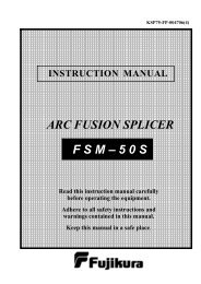
KSP75-FP-005120(3)<br />
INSTRUCTION MANUAL<br />
<strong>ARC</strong> <strong>FUSION</strong> <strong>SPLICER</strong><br />
F S M – 1 7 S<br />
Read this instruction manual carefully<br />
before operating the equipment.<br />
Adhere to all safety instructions and<br />
warnings contained in this manual.<br />
Keep this manual in a safe place.
Table of Contents<br />
Warnings and Cautions for Safe Operation..........................1<br />
Introduction ............................................................................6<br />
Description of Products ..........................................................8<br />
1. Components of Splicer .............................................................................................. 8<br />
2. Other Necessary Items for Splicing Operation ...................................................... 9<br />
3. Description and Function of Splicer...................................................................... 10<br />
Basic Operation ....................................................................12<br />
1. Inserting Power Supply into Splicer...................................................................... 12<br />
2. Turning splicer "ON".............................................................................................. 16<br />
3. Setting sleeve centering device ............................................................................... 17<br />
4. Cleaning optical fiber.............................................................................................. 17<br />
5. Placing protection sleeve over fiber....................................................................... 17<br />
6. Stripping and cleaning fiber................................................................................... 17<br />
7. Fiber Cleaving.......................................................................................................... 18<br />
8. Loading fiber into the splicer ................................................................................. 19<br />
9. Splicing procedure................................................................................................... 20<br />
10. Removing spliced fiber.......................................................................................... 26<br />
11. Transferring fiber to the tube heater................................................................... 26<br />
12. Heating protection sleeve...................................................................................... 26<br />
Maintenance of Splicing Quality .........................................28<br />
1. Cleaning and Checking before Splicing ................................................................ 28<br />
2. Periodical Checking and Cleaning ........................................................................ 30<br />
Splice Menu ..........................................................................34<br />
1. Splice Mode .............................................................................................................. 34<br />
2. Heater Mode............................................................................................................. 43<br />
3. Arc Calibration ........................................................................................................ 46<br />
4. Splice Option............................................................................................................ 48<br />
5. Splice Result............................................................................................................. 50<br />
Management Menu...............................................................54<br />
1. Change of Operating Direction.............................................................................. 54<br />
2. Power Save ............................................................................................................... 56<br />
3. Menu Lock / Power On Option / Other Option ................................................... 57
Table of Contents<br />
Maintenance Menu............................................................... 60<br />
1. Replace Electrode .................................................................................................... 61<br />
2. Stabilizing Electrodes.............................................................................................. 62<br />
3. Clearing Arc Count ................................................................................................. 63<br />
4. Battery Discharge.................................................................................................... 63<br />
5. Set Calendar............................................................................................................. 64<br />
6. Sensor Value ............................................................................................................. 64<br />
7. Diagnostic Test Function......................................................................................... 65<br />
8. Dust Check ............................................................................................................... 66<br />
9. Motor Drive.............................................................................................................. 67<br />
10. Maintenance Info................................................................................................... 67<br />
Error Message List ............................................................... 68<br />
Questions and Troubleshooting ........................................... 74<br />
1. Power Supply ........................................................................................................... 74<br />
2. Splicing Operation................................................................................................... 75<br />
3. Tube-heating Operation.......................................................................................... 77<br />
4. Supervising............................................................................................................... 77<br />
5. Other Functions....................................................................................................... 78<br />
Guarantee and Contact Address........................................... 79<br />
1. Guarantee................................................................................................................. 79<br />
2. Contact Address....................................................................................................... 80
Warning and Caution<br />
The FSM-17S has been designed for splicing Silica-based optical fibers for<br />
telecommunications. Do not attempt to use this machine for other applications.<br />
Fujikura Ltd. gives much consideration and regard to personal injury. Misuse of the<br />
machine may result in electric shock, fire and/or serious personal injury.<br />
Follow all safety instructions<br />
Read and understand all safety<br />
instructions.<br />
Stop using it when it malfunctions<br />
Ask our service centers for repair as<br />
soon as possible.<br />
Instruction Manual<br />
Read this instruction manual<br />
carefully before operating this<br />
machine.<br />
Store this instruction manual in a<br />
safe place.<br />
The following alert symbols are used in<br />
this instruction manual and machine to<br />
indicate warnings and caution for safe<br />
use. Understand the meanings of these<br />
symbols.<br />
!<br />
WARNING<br />
There is a possibility of death or serious<br />
injury resulting from improper use by<br />
ignoring this indication.<br />
!<br />
CAUTION<br />
There is a possibility of personal injury<br />
or physical loss resulting from<br />
improper use by ignoring this<br />
indication.<br />
Symbol means “Pay attention”<br />
Pay attention to hot surface!<br />
Symbol means “Must not do”<br />
You must not disassemble!<br />
Symbol means “Must do”<br />
You must disconnect a plug!<br />
1
Warning and Caution<br />
! WARNINGS<br />
Disconnect the AC power cord from the AC adapter inlet or the wall socket<br />
(outlet) immediately if user observes the following or if the splicer receives the<br />
following faults:<br />
• Fumes, bad smell, noise, or over-heat occurs.<br />
• Liquid or foreign matter falls into cabinet.<br />
• Splicer is damaged or dropped.<br />
If this occurs, ask our service center for repair. Leaving the splicer in a damaged<br />
state may cause equipment failure, electric shock or fire and may result in<br />
personal injury, death or fire.<br />
Use only the AC adapter / battery charger (ADC-11) designed for this splicer.<br />
Using an improper AC power source may cause fuming, electric shock or<br />
equipment damage and may result in personal injury, death or fire.<br />
Use the supplied AC power cord. Do not place heavy objects on the AC power<br />
cord. Use of an improper cord or a damaged cord may cause fuming, electric<br />
shock or equipment damage and may result in personal injury, death or fire.<br />
Do not disassemble or modify the splicer, AC adapter or battery. In particular, do<br />
not remove or bypass any electrical or mechanical device (e.g. a fuse or safety<br />
switch) incorporated into the design and manufacturing of this equipment.<br />
Modification could cause damage that may result in personal injury, death,<br />
electric shock or fire.<br />
Never operate the splicer in an environment where flammable liquids or vapors<br />
exist. Risk of dangerous fire or explosion could result from the splicer’s<br />
electrical arc in such an environment.<br />
Do not use compressed gas or canned air to clean the splicer. They may contain<br />
flammable materials that could ignite during the electrical discharge and also<br />
produce a film that contaminates the splicer’s lenses and mirrors.<br />
2
!<br />
Warning and Caution<br />
WARNINGS<br />
Do not touch the electrodes when the splicer is on and power is supplied to the<br />
unit. The electrodes generate high voltage and high temperatures that may cause<br />
a severe shock or burn.<br />
Note Arc discharge stops when wind protector is opened. Turn the splicer off<br />
and disconnect the AC power cord before replacing electrodes.<br />
Safety glasses should always be worn during fiber preparation and splicing<br />
operation. Fiber fragments can be extremely dangerous if they come into contact<br />
with the eye, skin, or are ingested.<br />
Use only proper power source.<br />
• Proper AC power source is AC100-240V, 50-60Hz. Check the AC power<br />
source before use. Proper DC power source is DC10-12V. Improper AC or<br />
DC power source may cause fuming, electric shock or equipment damage and<br />
may result in personal injury, death or fire.<br />
• AC generators commonly produce abnormally high AC output voltage or<br />
irregular frequencies. Measure the output AC voltage with a circuit tester<br />
before connecting the AC power cord. Such abnormally high voltage or<br />
frequency from a generator may cause fuming, electric shock or equipment<br />
damage and may result in personal injury, death or fire. Make sure the<br />
generator is regularly checked and serviced.<br />
• An AC Adapter Protection Circuit is included in the ADC-11 AC Adapter. If<br />
the “High AC Input” lamp of the AC adapter is lit or the protection circuit in<br />
the AC adapter is tripped, this indicates that the incoming voltage is<br />
dangerously high and may cause injury or damage to the equipment, as<br />
mentioned above. When using an AC generator with AC output voltage of<br />
AC220-240V especially, Fujikura Ltd. recommends the following measures<br />
to correct the condition.<br />
(1) Connect a step-down transformer between the generator and the AC<br />
adapter in order to lower the AC voltage from AC220-240V to<br />
AC100-120V.<br />
(2) Or, use an AC generator with AC output voltage of AC100V.<br />
(3) Or, use an AC generator that has an inverter circuit to stabilize the output.<br />
Do not modify, abuse, heat or excessively pull on the supplied AC cord. The use<br />
of a damaged cord may cause fuming, electric shock or equipment damage and<br />
may result in personal injury, death or fire.<br />
The FSM-17S uses a three-prong (core) AC cord that contains an earthed ground<br />
safety mechanism. The splicer MUST be Grounded. Use only the supplied<br />
three-prong (core) AC power cord. NEVER use a two-prong (core) power cord,<br />
extension cable or plug.<br />
3
Warning and Caution<br />
!<br />
WARNINGS<br />
Connect AC power cord properly to the splicer (inlet) and wall socket (outlet).<br />
When inserting the AC plug, make sure there is no dust or dirt on the terminals.<br />
Engage by pressing the female plug into the splicer (inlet) and the male plug into<br />
the wall socket (outlet) until both plugs are fully seated. Incomplete engagement<br />
may cause fuming, electric shock or equipment damage and may result in<br />
personal injury, death or fire.<br />
Do not short-circuit the terminals of AC adapter (ADC-11) and optional battery<br />
(BTR-06). Excessive electrical current may cause personal injury due to fumes,<br />
electric shock and equipment damage.<br />
Do not touch the splicer, AC power cord and AC plugs with wet hands. This may<br />
result in electric shock.<br />
Do not operate splicer near hot objects, in hot temperature environments, in<br />
dusty / humid atmospheres or when water-condensation is present on the splicer.<br />
This may result in electric shock, splicer malfunction or poor splicing<br />
performance.<br />
When using optional battery (BTR-06), follow the instructions below.<br />
Failure to follow these may result in explosion or personal injury.<br />
• Do not charge battery with other methods than instructed.<br />
• Do not discard battery into an incinerator or fire.<br />
• Do not charge or discharge battery near a flame or under direct sunlight.<br />
• Do not excessively shake or jar the battery.<br />
• If battery leaks of liquid residue, be careful handling the battery so the liquid<br />
does not get in skin or eye contact. If it reaches contact, immediately wash<br />
skin or eyes thoroughly and see the doctor. Dispose of the battery and call<br />
the service center for replacement.<br />
• Do not stack battery on top of AC adapter while charging.<br />
• If charge did not complete in three hours or the "CHARGE" LED does not<br />
turn ON, immediately stop charging and call the service center for repair.<br />
When transporting the carrying case using the shoulder belt, check the belt and<br />
hooks for damage before use. Carrying the case with a damaged shoulder belt<br />
may cause the belt to break or come off and result in personal injury or<br />
equipment damage.<br />
4
Warning and Caution<br />
!<br />
CAUTIONS<br />
Do not store splicer in any area where temperature and humidity are extremely<br />
high. Possible equipment failure may result.<br />
Do not touch protection sleeve or tube-heater during heating or immediately<br />
after completion of heating. Their surfaces are very hot and touching these may<br />
result in skin burn.<br />
Do not place the splicer in an unstable or unbalanced position. The splicer may<br />
shift or lose balance, causing the unit to fall. Possible personal injury or<br />
equipment damage may result.<br />
The splicer is precision adjusted and aligned. Do not allow the unit to receive a<br />
strong shock or impact. Possible equipment failure may result. Use supplied<br />
carrying case for transportation and storage. The carrying case protects the<br />
splicer from damage, moisture, vibration and shock during storage and<br />
transportation.<br />
Follow the below listed instructions for handling electrodes.<br />
• Use only specified electrodes.<br />
• Set the new electrodes in the correct position.<br />
• Replace the electrodes as a pair.<br />
Failure to follow the above instructions may cause abnormal arc discharge. It<br />
can result in equipment damage or degradation in splicing performance.<br />
Do not use any chemical other than pure alcohol (99% or greater) to clean the<br />
objective lens, V-groove, mirror, LCD monitor, etc., of the splicer. Otherwise<br />
blurring, discoloration, damage or deterioration may result.<br />
The splicer requires no lubrication. Oil or grease may degrade the splicing<br />
performance and damage the splicer.<br />
The equipment must be repaired or adjusted by an authorized technician or<br />
engineer. Unauthorized incorrect repair may cause fire or electric shock.<br />
Should any problems arise, please contact your nearest sales agency.<br />
5
Introduction<br />
The FSM-17S arc fusion splicer is designed<br />
for splicing many types of optical single fiber.<br />
It is small in size and lightweight, making it<br />
suitable for any operating environment. It is<br />
easy to operate and it splices fast while<br />
maintaining low splice loss. In order to<br />
achieve the splicer’s full capabilities, read the<br />
following important information.<br />
Splice modes<br />
The FSM-17S has not only standard splice<br />
modes, but also automatic modes, AUTO<br />
mode. The AUTO mode consists of<br />
[AUTO], [SM AUTO], [NZ AUTO], [DS<br />
AUTO], [MM AUTO] mode. When using<br />
AUTO mode, the automatic arc calibration<br />
function is enabled.<br />
The standard modes consists of [SM] for SMF (ITU-T G652), [NZ] for NZDSF<br />
(ITU-T G655), [DS] for DSF (ITU-T G653) and [MM] for MMF (ITU-T G651). Refer<br />
Page34.<br />
Automatic arc calibration function<br />
This function calibrates the arc power at every splice. When the automatic arc<br />
calibration function is enabled, performing the [Arc calibration] function before a<br />
splice operation is not necessary. The automatic arc calibration function works in the<br />
AUTO mode only. It doesn’t work in the standard modes. When using the standard<br />
modes, performing [Arc calibration] before splicing is strongly recommended.<br />
6
Introduction<br />
Useful functions<br />
(1) Change of operating direction<br />
The FSM-17S has the ability to operate<br />
when the monitor is in the front or rear<br />
of the splicer. The right figure shows the<br />
operation setting when the monitor is<br />
positioned to the rear. To change the<br />
monitor position, refer to “Change of<br />
Operating Direction” on page 54.<br />
(2) Protection sleeve centering device<br />
The FSM-17S has a built in centering<br />
device to center the fiber protection<br />
sleeve in the tube heater. Refer to<br />
“Removing spliced fiber” on page 26.<br />
Notes<br />
LCD (Liquid Crystal Display) monitor<br />
The FSM-17S splicer is equipped with a LCD monitor, manufactured in a high<br />
quality-controlled factory environment. However, some black dots may appear,<br />
or red/blue/green dots may remain on the screen. The screen brightness may not<br />
appear uniform, depending on viewing angle. Note that these symptoms are not<br />
defects, but are natural on LCDs.<br />
Recycling<br />
To recycle this product, disassemble it first, sort each part separately by material<br />
components and follow your local recycling and disposal regulations.<br />
Related patents of FSM-17S<br />
US Patent No.<br />
4978201, 5009513, 5122638, 5228102<br />
EPC No.<br />
326988, 320978, 504519<br />
Canada Patent No.<br />
1309773, 1316719, 2051363<br />
7
Description of Products<br />
1. Components of Splicer<br />
Working Table<br />
[ WT-06 ] (OPTION)<br />
See a note below.<br />
Monitor Cover<br />
[ MC-02 ]<br />
Spare Electrodes<br />
1 pair<br />
[ ELCT2-20A ]<br />
<br />
Magnifier<br />
[MGS-05]<br />
(OPTION)<br />
J-Plate [ JP-04 ]<br />
(OPTION)<br />
Arc Fusion Splicer<br />
[ FSM-17S ]<br />
AC Adapter /<br />
Battery Charger<br />
[ ADC-11 ]<br />
DC Power Cord<br />
(OPTION)<br />
AC Power Cord<br />
[ DCC-12 ]<br />
[ DCC-13 ]<br />
Wind Protector<br />
Mirror<br />
[ WPM-07 ]<br />
(OPTION)<br />
Battery Pack L<br />
[ BTR-06L ]<br />
(OPTION)<br />
Battery Pack S<br />
[ BTR-06S ]<br />
(OPTION)<br />
Battery Charge Cord<br />
[ DCC-10 ]<br />
(OPTION)<br />
Other Attached Items<br />
• Carrying Case [ CC-12 ]<br />
• Instruction Manual<br />
Note<br />
• To attach the working table [ WT-06 ], a working table support [WTS-06] is<br />
also necessary.<br />
• Wind Protector Mirror [ WPM-07 ] is maintenance part. For replacement,<br />
refer to [ Cleaning Wind Protector Mirrors ] (page29) .<br />
8
2. Other Necessary Items for Splicing Operation<br />
Description of Products<br />
Fiber coating<br />
diameter<br />
0.25mm<br />
Standard sleeve<br />
60mm length [ FP-03 ]<br />
40mm length [ FP-03 ( L = 40 ) ]<br />
0.9mm<br />
Fiber<br />
protection<br />
sleeves<br />
Micro sleeve<br />
20mm length [ FPS01-250-20 ]<br />
25mm length [ FPS01-250-25 ]<br />
34mm length [ FPS01-250-34 ]<br />
Micro sleeve<br />
45mm length [ FPS01-900-45 ]<br />
Fiber<br />
stripping<br />
tools<br />
Primary coat stripper [ PS-02 ] Jacket stripper [ JS-01 ]<br />
Fiber<br />
cleaving<br />
tools<br />
Fiber<br />
cleaning<br />
tools<br />
Fiber Cleaver [CT-20]<br />
Fiber Plate [ AD-11 ]<br />
Cleave length : 16mm fixed<br />
Fiber Plate [ AD-12 ]<br />
Cleave length : 8 to 20mm<br />
Alcohol dispenser with<br />
alcohol (purity > 99% )<br />
Fiber Plate [ AD-11 ]<br />
Cleave length : 16mm fixed<br />
Fiber Plate [ AD-12 ]<br />
Cleave length : 16 to 20mm<br />
Lint-free tissue or gauze<br />
9
Description of Products<br />
3. Description and Function of Splicer<br />
Wind protector<br />
Tube heater<br />
Video output terminal<br />
(NTSC)<br />
USB port<br />
HJS power port<br />
LCD monitor<br />
Power unit dock<br />
10
Description of Products<br />
V-groove<br />
Electrode cover<br />
Electrode<br />
Objective lens<br />
Sheath clamp<br />
Sheath clamp<br />
Electrode cover<br />
Electrode<br />
Illumination lamp<br />
Wind protector<br />
mirror<br />
Fiber clamp<br />
11
Basic Operation<br />
1. Inserting Power Supply into Splicer<br />
For AC operation or DC operation with external battery, use the AC adapter (ADC-11).<br />
For battery operation, use the detachable battery (BTR-06S/L). The Power Unit Dock,<br />
located on the splicer body, can accommodate both power supplies (ADC-11 and<br />
BTR-06S/L).<br />
1-1. Inserting or detaching power unit<br />
Inserting power supply unit<br />
Insert power unit into Power unit dock until<br />
it clicks into place.<br />
Insert<br />
Detaching power supply unit.<br />
Turn off the splicer. Push the release button,<br />
located on the side of the splicer body, and<br />
remove the power supply out of the splicer<br />
body.<br />
Pull the power unit<br />
1-2. AC Operation<br />
Plug the supplied AC cord into the AC inlet<br />
of the AC adapter. The power ON LED in<br />
the AC adapter turns on (green color) when<br />
suitable AC voltage is supplied. In case of<br />
AC350V (Peak Voltage: 490V) or greater is<br />
supplied, the AC adapter protection circuit<br />
shuts down the AC output and the AC<br />
Warning LED [HIGH ~ INPUT] turns on<br />
(red color). And, in case of AC400V (Peak<br />
Voltage: 560V) or greater is supplied, the<br />
AC adapter will be immediately broken.<br />
AC warning<br />
LED (RED)<br />
Insert<br />
Release button<br />
Power ON LED<br />
(GREEN)<br />
• Do not cover any of the AC adapter vents. Allow at least one-inch air gap<br />
between wall and splicer in order to circulate fresh air.<br />
12
Basic Operation<br />
1-3. DC operation with external battery<br />
Open shutter for DC inlet of AC<br />
adapter.<br />
Open<br />
Plug DC cord (DCC-12 or DCC-13)<br />
into DC inlet of AC adapter. The ON<br />
LED turns on (green color) when<br />
suitable DC voltage is supplied. If 16V<br />
DC or greater is supplied, or polarity<br />
(positive / negative) is wrong, The AC<br />
adapter protection circuit shuts down<br />
the DC output and DC Warning LED<br />
[HIGH ~ INPUT] turns on (red color).<br />
DC warning LED<br />
Insert<br />
13
Basic Operation<br />
1-4. Battery operation<br />
Check and make sure the remaining battery capacity is 20% or greater before operation;<br />
otherwise few splices can be made. To prevent battery degradation due to the memory<br />
effect, discharge it completely at least once a month. See [Battery Discharge] (page 63)<br />
for more details.<br />
Two ways to check remaining battery capacity<br />
If the battery is already inserted in the splicer, turn splicer ON. Power source of<br />
"Battery" is automatically identified and the remaining battery capacity is displayed<br />
on the "READY" screen.<br />
Or press battery check button (1) on the battery pack. The remaining battery<br />
capacity is indicated on the LED indicator (2).<br />
READY screen<br />
Remaining battery capacity indicator<br />
2<br />
1<br />
Remaining battery capacity<br />
display<br />
(Blue Color)<br />
(Green Color)<br />
(Green Color)<br />
(Yellow Color)<br />
(Red Color)<br />
Remaining battery capacity Remaining<br />
indicator<br />
battery<br />
5 LED 80100%<br />
4 LED 6080%<br />
3 LED 4060%<br />
2 LED 2040%<br />
1 LED Less than 20%<br />
1 LED Flashing Less than 10%<br />
No LED 5% or less<br />
14
Basic Operation<br />
How to charge the battery<br />
Open shutter for battery charge<br />
plug inlet of the AC adapter<br />
(ADC-11). Plug the supplied<br />
battery charge cord (DCC-11) into<br />
both the battery charge inlet of the<br />
AC adapter (ADC-11) and the<br />
battery charge terminal located on<br />
the battery (BTR-06S/L) side. Do<br />
not place the battery on top of the<br />
AC adapter or vise-versa. The<br />
CHARGE LED turns ON (orange<br />
color) and battery charging begins.<br />
Battery charge is completed in<br />
approximately three hours. After<br />
completion, disconnect AC cord,<br />
then charge cord.<br />
Open<br />
• Battery can be charged while AC adapter (ADC-11) is in power unit dock<br />
but splicer cannot be turned ON.<br />
• CHARGE LED turns off when battery charge is completed. If CHARGE<br />
LED flashes, replace the battery with a new one.<br />
• If battery charge does not complete in three hours or CHARGE LED does<br />
not turn ON, the battery, AC adapter or both need replacement. Ask your<br />
service agent for further instruction.<br />
15
Basic Operation<br />
2. Turning splicer "ON"<br />
Press and hold until the LED on the keypad<br />
turns "ON" (green color). The READY screen<br />
is displayed after all the motors reset to their<br />
initial positions. The power source type is<br />
then identified. If the battery is used, the<br />
remaining battery capacity is displayed.<br />
Monitor Angle<br />
Adjust the monitor angle to comfortably see the view screen.<br />
Monitor brightness<br />
Monitor visibility is sometimes low<br />
depending on environmental conditions.<br />
To change the monitor brightness, press<br />
or<br />
to change value and press to set<br />
value.<br />
READY<br />
Splice Mode<br />
Select appropriate splicing mode for the<br />
specific fiber combination. The current<br />
mode is displayed on the READY screen.<br />
• When selecting AUTO mode, arc<br />
calibration is automatically<br />
performed for consistent splicing<br />
performance.<br />
Heat Mode<br />
Select appropriate heating mode for the<br />
specific protection sleeve used. The<br />
current mode is displayed on the READY<br />
screen.<br />
• To change the splice mode, press<br />
at READY screen. To change<br />
to heater mode, press again.<br />
Screen image will go to [Splice<br />
Mode Select] menu and [Heater<br />
Mode Select] menu respectively.<br />
Monitor brightness control menu<br />
Decided<br />
16
Basic Operation<br />
3. Setting sleeve centering device<br />
Open tube heater lid, and slide gauge<br />
indicator to match the length of<br />
protection sleeve used.<br />
Move by finger<br />
Sleeve length<br />
4. Cleaning optical fiber<br />
Clean optical fiber with alcohol-impregnated gauze or lint-free tissue approximately<br />
100mm from the tip. If the fiber is not cleaned properly, dust particulates from the fiber<br />
coating surface can enter inside the protection sleeve and might result in a future fiber<br />
break or attenuation increase.<br />
5. Placing protection sleeve over fiber<br />
Place the protection sleeve<br />
over the fiber. The sleeve will<br />
be shrunk down in the tube<br />
heater after the splice is<br />
complete.<br />
Fiber protection sleeve<br />
Pass fiber<br />
Fiber<br />
6. Stripping and cleaning fiber<br />
Strip outer coating 30 to 40 mm from its tip with a stripping tool. Clean the fiber<br />
thoroughly with alcohol impregnated gauze or lint-free tissue. Use fresh gauze or wipe<br />
only. Do not use gauze or wipe twice.<br />
Stripping<br />
• Use a high quality alcohol, greater than 99% pure.<br />
Cleaning<br />
17
Basic Operation<br />
7. Fiber Cleaving<br />
(1) To unlock the anvil lever, press the anvil lever down gently. Next, slide the<br />
stopper to the unlock position to open the anvil lever. Then slide the upper clamp<br />
stopper.<br />
Upper clamp stopper<br />
Stopper<br />
(2) Set the stripped optical fiber on the cleaver. Verify the proper cleave length.<br />
(3) Press down the anvil lever slowly until the cleaver blade scratches the fiber.<br />
(4) Press down the anvil lever quickly like striking when the anvil cleaves the fiber.<br />
(5) Slowly release the pressure on the anvil lever. A spring force will bring it to its<br />
open position.<br />
Fiber plate<br />
(AD-13)<br />
Anvil lever<br />
30mm<br />
• Proper operation of the anvil lever can be seen at URL<br />
http://www.fujikura.co.jp/splicer/ct20/operate.mpg<br />
(6) Remove and discard fiber fragments and put into a proper disposal container, or use<br />
the lever to discard fiber into the fiber disposer. Fiber fragments in the fiber<br />
disposer should be placed in proper disposal container regularly.<br />
(7) Slide the upper clamp stopper to storage position.<br />
(8) When the cleaver is to be put up for the day, press the anvil lever down, until the<br />
stopper can slide into place to lock the anvil lever.<br />
18
8. Loading fiber into the splicer<br />
(1) Open the wind protector and<br />
sheath clamps.<br />
(2) Place prepared fiber onto v-groove<br />
so that the fiber tip is located<br />
between the v-groove edge and tip<br />
of electrode.<br />
Sheath clamp<br />
Basic Operation<br />
Fiber<br />
Electrode<br />
• If fiber coating has some memory curl, place fiber so that the curve of<br />
memory is turned downward.<br />
• Be careful to not bump the prepared fiber tips into anything to maintain<br />
fiber end -face quality.<br />
(3) Hold fiber with fingers and close<br />
sheath clamp so that the fiber does not<br />
move. Make sure the fiber is placed<br />
in the bottom of the v-grooves. If<br />
fiber is not placed properly, reload<br />
fiber.<br />
(4) Load another fiber in the same<br />
manner as in step (3) above.<br />
(5) Close wind protector.<br />
19
Basic Operation<br />
9. Splicing procedure<br />
To assure a good splice, the optical fiber is observed with the image processing system<br />
equipped in the FSM-17S. However, there are some cases when the image processing<br />
system cannot detect a faulty splice. Visual inspection with the monitor is often<br />
necessary for better splicing yield. The procedure below describes this process.<br />
(1) Fibers loaded in the splicer move<br />
forward. The forward motion of the<br />
fiber stops at a certain position shortly<br />
after the cleaning arc is performed.<br />
Next, the offset, the cleave angle and<br />
end-face quality are checked. If the<br />
measured offset and cleave angle is<br />
greater than its set threshold or fiber<br />
chipping is detected, the buzzer will<br />
sound and an error message will warn<br />
the operator. The splicing procedure<br />
pauses.<br />
The end-face conditions below are<br />
used for visual inspection, if observed,<br />
remove the fiber from the splicer and<br />
repeat fiber preparation. These visual<br />
defects may cause a faulty splice.<br />
Left cleave angle<br />
Right cleave angle<br />
Axis offset<br />
Chip Lip Incline<br />
• Pause after offset, cleave angle check can be set to disabled. See [Splice<br />
Option] (Page 48) for details.<br />
• The cleave angle and offset threshold can be changed. See [Splice Option]<br />
(Page 48) for details.<br />
• The offset and cleave angle error messages can be ignored by pressing SET<br />
to go on to the next step. To disable the cleave angle error, see [Splice<br />
Option] (Page 48) for details.<br />
• Cleave angle, cladding axis offset during the splicing operation can be<br />
hidden. See [Splice Option] (Page 48) for details.<br />
20
(2) After completion of fiber checking,<br />
arc discharge is performed to splice<br />
the fibers.<br />
<br />
<br />
Basic Operation<br />
(3) Estimated splice loss is displayed<br />
upon completion of splicing. Splice<br />
loss is affected by certain factors,<br />
such as MFD, stated in the next page.<br />
These factors are taken into account<br />
to estimate splice loss.<br />
If either the cleave angle measured<br />
or<br />
the estimated splice loss exceeds its<br />
set threshold, an error message is<br />
displayed. If the spliced fiber is<br />
detected as being abnormal, such as<br />
“Fat”, “Thin” or “Bubble”, “Large<br />
Dust Burn” an error message is<br />
displayed.<br />
If no error message is displayed but the splice looks poor by visual inspection<br />
through the monitor, it is strongly recommended to repeat the splice from the<br />
beginning.<br />
• The splice point sometimes looks a bit fatter than other parts. This is<br />
considered a normal splice, and does not affect splice loss.<br />
• To change threshold for estimated splice loss or cleave angle, see [Splice<br />
Mode] (Page 34) for details.<br />
• Error messages, such as "Estimated splice loss", "Splice angle", "Fat", "Thin"<br />
and "Bubble" can be ignored. This function can be set to "disabled". See<br />
[Splice Option] (Page 48) for details.<br />
Splice loss may be improved in some cases by additional arc discharges.<br />
Press <strong>ARC</strong> for an additional arc discharge (re-arc). Splice loss estimate and<br />
splice check are performed again.<br />
• Splice loss may be worsened in some cases by additional arc discharges<br />
(re-arcs). Additional arc discharge can be set to "disabled", or limited to the<br />
number of additional arcs. See [Splice Option] (Page 48) for details.<br />
21
Basic Operation<br />
Splice loss increase : Cause and remedy<br />
Symptom Cause Remedy<br />
Clad axial offset<br />
Dust on v-groove or<br />
fiber clamp chip<br />
Clean v-groove and fiber clamp chip.<br />
Combustion<br />
Bubbles<br />
Separation<br />
Fat<br />
Thin<br />
Line<br />
Bad fiber end-face<br />
quality<br />
Dust still present<br />
after cleaning fiber<br />
or cleaning arc.<br />
Bad fiber end-face<br />
quality<br />
Prefuse power too<br />
low, or prefuse time<br />
too short.<br />
Fiber stuffing too<br />
small<br />
Prefuse power too<br />
high, or prefuse time<br />
too long.<br />
Fiber stuffing too<br />
much<br />
Arc power not<br />
adequate<br />
Some arc parameters<br />
not adequate<br />
Some arc parameters<br />
not adequate<br />
Check the cleaver<br />
Clean fiber thoroughly or<br />
Increase [Cleaning Arc Time]<br />
Check cleaver condition.<br />
Increase [Prefuse Power] and/or [Prefuse<br />
Time].<br />
Increase [Overlap]<br />
Decrease [Prefuse Power] and/or [Prefuse<br />
Power].<br />
Decrease [Overlap]<br />
Perform [Arc Calibration].<br />
Adjust [Prefuse Power], [Prefuse Time] or<br />
[Overlap].<br />
Adjust [Prefuse Power], [Prefuse Time] or<br />
[Overlap].<br />
• A vertical line sometimes appears at the splice point when MM fibers, or<br />
dissimilar fibers ( different diameters ) are spliced. This does not affect<br />
splice quality, such as splice loss or tensile strength.<br />
22
Basic Operation<br />
BLANK PAGE<br />
23
Basic Operation<br />
Storing splicing results<br />
Splicing results can be stored in memory. Follow the storing procedure below.<br />
• After the 2000th result is stored, the 2001st splice result is written over the<br />
1st result.<br />
Storing results automatically (No comment is inputted)<br />
The splice result is automatically stored in memory when SET or RESET is<br />
pressed upon completion of the splice at the [FINISH] screen, or when the wind<br />
protector is opened upon completion of the splice at the [FINISH] screen.<br />
Once a certain comment is inputted, the same comment is inputted into subsequent<br />
splice results. To change comments, see next paragraph.<br />
Storing results with comments<br />
Press at [FINISH] screen upon completion of the splice to display [Memory<br />
Storage Menu]. Move cursor to [Storage/Comment Input] and press to display<br />
[Input Comment] screen, then input comment. Press SET , RESET or open wind<br />
protector at the [FINISH] screen to store splicing results with comments.<br />
Memory Storage Cancel<br />
Press at the [FINISH] screen upon completion of the splice to display [Memory<br />
Storage Menu]. Move cursor to [Memory Storage Cancel] and press to enter. No<br />
splicing results are stored even though SET or RESET is pressed, or wind protector<br />
is opened at the [FINISH] screen upon completion of the splice.<br />
• [Memory Storage Cancel] function can be set to "disabled". See<br />
[Management Menu] (Page 54) for details.<br />
24
Basic Operation<br />
[FINISH] State<br />
Select<br />
[Input Comment]<br />
Select<br />
[Cancel Storage]<br />
SET , RESET or “Cover opened”<br />
Automatic storage<br />
with same comment<br />
Data storage<br />
Storage<br />
with comment input<br />
Storage<br />
cancel<br />
No data storage<br />
25
Basic Operation<br />
10. Removing spliced fiber<br />
(1) Open lids of tube heater.<br />
(2) Open wind protector.<br />
(3) Hold left fiber with left hand at the edge<br />
of wind protector and open left sheath<br />
clamp.<br />
• Keep holding fiber until fiber is<br />
completely transferred to the tube<br />
heater.<br />
(4) Open right sheath clamp.<br />
(5) Hold right fiber with right hand, and<br />
remove spliced fiber from the splicer.<br />
Hold left fiber with left hand at the<br />
edge of wind protector.<br />
11. Transferring fiber to the tube heater<br />
Holding the fiber with the left hand, place<br />
protection sleeve on the centering device<br />
located on the tube heater. Length gauge is set<br />
according to sleeve length in advance. Slide<br />
spliced fiber slowly to the right until left hand<br />
reaches the edge of the tube heater. At this<br />
point the sleeve is centered and ready for<br />
replacement in the tube heater.<br />
Slide spliced fiber to the right until<br />
left hand reaches the edge of tube<br />
heater.<br />
• Splice point can be set in the<br />
center of the protection sleeve<br />
using the centering device located<br />
on the tube heater.<br />
Place protection sleeve<br />
in centering device.<br />
12. Heating protection sleeve<br />
(1) Transfer fiber with protection sleeve<br />
from centering device to tube heater<br />
(2) Place fiber with protection sleeve in tube<br />
heater. While placing it in the tube<br />
heater, apply tension to the fiber so the<br />
tube heater lids automatically close.<br />
26<br />
•Make sure the splice point is<br />
located at the center of the<br />
protection sleeve.<br />
•Make sure the strength member in<br />
the protection sleeve is placed<br />
downwards.
Basic Operation<br />
(3) Press HEAT to start tube heater. The buzzer beeps and the HEAT LED (orange<br />
color) turns off when heating cycle is completed.<br />
• If HEAT is pressed during tube heating, the HEAT LED blinks.<br />
If HEAT is pressed again, the tube heating process is aborted.<br />
(4) Open tube heater lids and remove protected fiber from the tube heater. Apply<br />
tension to the fiber while removing it from the tube heater.<br />
• Protection sleeve may stick to bottom plate of heater. Use a cotton swab to<br />
help remove sleeve from heater.<br />
(5) Visually inspect the finished sleeve to verify no bubbles or debris/dust are present<br />
in the sleeve.<br />
27
Maintenance of Splicing Quality<br />
1. Cleaning and Checking before Splicing<br />
Critical cleaning points and maintenance checks are described below.<br />
1-1. Cleaning V-grooves<br />
If contaminants are present in the V-grooves, proper clamping may not occur, resulting<br />
in higher splice loss. The V-grooves should be frequently inspected and periodically<br />
cleaned during normal operation. To clean the V-grooves, do the following:<br />
(1) Open the wind protector.<br />
(2) Clean the bottom of the V-groove<br />
with an alcohol-impregnated thin<br />
cotton swab. Remove excess<br />
alcohol from the V-groove with a<br />
clean dry swab.<br />
•Be careful to not contact the<br />
electrode tips.<br />
•Do not use excessive force<br />
when cleaning the V-groove.<br />
The V-groove arm may get<br />
damaged.<br />
Cotton swab<br />
V-grooves<br />
(3) If the contaminants in the V-groove<br />
cannot be removed with an<br />
alcohol-impregnated thin cotton<br />
swab, use a cleaved fiber end-face to<br />
dislodge contaminants from the<br />
bottom of the V-groove. Repeat step<br />
(2) after this procedure.<br />
Cleaved fiber<br />
V-grooves<br />
28
Maintenance of Splicing Quality<br />
1-2. Cleaning Fiber Clamp Chips<br />
If contaminants are present on the clamp<br />
chips, proper clamping may not occur,<br />
resulting in poor quality splices. The fiber<br />
clamp chips should be frequently inspected<br />
and periodically cleaned during normal<br />
operation. To clean the clamp chips, do the<br />
following:<br />
Cotton swab<br />
(1) Open the wind protector.<br />
(2) Clean the surface of the clamp chip<br />
with an alcohol-impregnated thin<br />
cotton swab. Remove excess alcohol<br />
from the clamp chip with a clean dry<br />
swab.<br />
Fiber clamp<br />
1-3. Cleaning Wind Protector Mirrors<br />
If the wind protector mirrors become dirty,<br />
the fiber position may be incorrect due to<br />
decreased optical path clarity, resulting in<br />
higher splice loss. To clean the mirrors,<br />
do the following:<br />
Cotton swab<br />
(1) Clean the mirror surface with an<br />
alcohol-impregnated thin cotton<br />
swab. Remove excess alcohol from<br />
the mirror surface with a clean dry<br />
swab.<br />
(2) The mirror should look clean with no<br />
streaks or smudges.<br />
Wind Protector Mirror<br />
1-4. Cleaning Fiber Cleaver<br />
If the cleaver blade or clamp pads of the fiber<br />
cleaver become contaminated, the cleaving<br />
quality could degrade. This may lead to fiber<br />
surface or end-face contamination, resulting in<br />
higher splice loss. Clean the cleaver blade and<br />
clamp pads with an alcohol-impregnated thin<br />
cotton swab.<br />
1-5. Arc Power Calibration<br />
Refer to [Arc Calibration] (Page 46).<br />
Blade<br />
Elastomer clamp pad<br />
29
Maintenance of Splicing Quality<br />
2. Periodical Checking and Cleaning<br />
In order to maintain the splicing quality, periodical inspection and cleaning are<br />
recommended.<br />
2-1. Cleaning Objective Lenses<br />
If the surface of objective lens becomes dirty, observation of the fiber position may be<br />
incorrect, resulting in higher splice loss or poor splicer operation. Therefore, clean both<br />
lenses at regular intervals. Otherwise, dirt may accumulate and become impossible to<br />
remove. To clean the objective lenses, do the following:<br />
(1) Before cleaning the objective lenses, always turn off the splicer.<br />
(2) Gently clean the lenses’ (X-axis and Y-axis) with an alcohol-impregnated thin<br />
cotton swab. Using the cotton swab, start at the center of the lens and move the<br />
swab in a circular motion until you spiral out to the edge of the lens. Remove<br />
excess alcohol from the lens surface with a clean dry swab.<br />
• Remove electrode before cleaning objective lens.<br />
• Do not hit or touch tip of electrode when cleaning.<br />
Objective lens<br />
Cotton swab<br />
Objective lens<br />
Cleaning<br />
Objective lens<br />
(3) The lens surface should be clean and free of streaks or smudges.<br />
(4) Turn on the power and make sure no smudges or streaks are visible on the monitor<br />
screen. Press X/Y to change the screen and check the state of the lens surface on<br />
both the X- and Y-screens. Perform the dust check procedure.<br />
30
Maintenance of Splicing Quality<br />
2-2. Rotating Cleaver Blade<br />
If the cleaver does not cleave properly, rotate the blade 1/16th of a turn to replace the<br />
worn out blade position with a sharp blade position. Blade life is normally 1000 cleaves<br />
per blade position. To rotate the blade, do the following:<br />
(1) Remove the blade cover.<br />
(2) Using a small slotted screwdriver, loosen the blade lock screw.<br />
(3) Rotate the circular blade 1/16th of a turn.<br />
• When rotating the blade, do not touch the cutting edge. Move the blade<br />
with a thin cotton swab, for easy and safe rotation.<br />
(4) Tighten the blade lock screw.<br />
(5) Attach the blade cover.<br />
Blade Height Adjustment<br />
After the circular blade has been rotated a complete revolution (16 positions), blade<br />
height needs to be adjusted to compensate for blade wear. There are 3 blade heights<br />
which may be utilized. To change the blade height, perform the following:<br />
(1) Loosen the blade lock screw.<br />
(2) Using a .89mm hex wrench, loosen the adjuster lock screw.<br />
(3) Using a 1.5mm hex wrench, turn the adjuster clockwise so that the reference dot<br />
aligns with the next position mark. Never attempt to rotate the adjuster more than 2<br />
position marks.<br />
(4) Tighten the adjuster lock screw.<br />
(5) Tighten the blade lock screw.<br />
• After blade height adjustment, the 16 blade positions can be used again. If<br />
the cleaver does not cleave properly, rotate the blade.<br />
Adjuster lock screw<br />
(Set screw M2x3)<br />
Adjuster<br />
Adjuster<br />
initial<br />
position<br />
Blade lock screw<br />
(Cone point set screw M3x4)<br />
Direction of<br />
rotation<br />
Blade Replacement<br />
After the circular blade is raised 3 times and rotated through all positions (a total of<br />
approximately 48,000 fiber splices), it needs to be replaced. Contact your Fujikura<br />
splicer distributor.<br />
31
Maintenance of Splicing Quality<br />
2-3. Replace Wind Protector Mirrors<br />
Replace the wind protector mirror if it cannot be cleaned or if it remains cloudy. To<br />
replace, do the following:<br />
(1) Turn the splicer power off.<br />
(2) Open the wind protector. With fingers, pull and unlock wind protector mirror latch.<br />
While still pulling on mirror latch, use other hand to pull on the wind protector<br />
mirror frame. The frame should raise and rotate back. Pull out the mirror from its<br />
frame.<br />
Wind protector mirror<br />
Wind protector<br />
mirror latches<br />
Latch off with finger<br />
Raise wind<br />
protector mirror<br />
frame<br />
Pull wind protector mirror<br />
(3) Insert new mirror into the frame. The clear glass side should face upward while<br />
inserting mirror into the frame. The opposite side of the mirror is not covered with<br />
clear glass. To identify the clear side of mirror put a cotton swab on one of the<br />
mirror sides. If it is the clear side, there will be some distance found between the<br />
cotton swab and the mirror base because the clear glass cover is located in between<br />
the cotton swab and mirror.<br />
Distance<br />
No distance<br />
Right side<br />
Reverse side<br />
• Make sure the wind protector mirror is inserted correctly. If not, the fiber<br />
cannot be observed correctly.<br />
32
Maintenance of Splicing Quality<br />
(4) Clean Wind Protector Mirrors.<br />
(5) Turn on the power and make sure no smudges or streaks are visible on the monitor<br />
screen. Press X/Y to change the screen and check the state of the lens surface on<br />
both the X- and Y-screens. Perform dust check.<br />
2-4. Electrode Replacement<br />
Refer to Page 61 [Replace Electrode].<br />
2-5. Diagnostic Test<br />
Refer to Page 65 [Diagnostic Test Function].<br />
2-6. Complete Discharge of Battery Pack<br />
Refer to Page 63 [Battery Discharge].<br />
2-7. Adjust Monitor Angle Adjuster<br />
(1) The monitor hinge may become too loose and not maintain the monitor position.<br />
To fix this problem, tighten monitor hinge screws shown in following picture.<br />
Monitor hinge screws<br />
(2) The monitor hinge may become difficult to adjust the monitor angle. To fix this<br />
problem, apply oil to position shown in the following picture. Do not tighten the<br />
screws.<br />
33
Splice Menu<br />
1. Splice Mode<br />
The optimum splice setting for a specific fiber combination consists of the below listed<br />
splicing parameters. In other words, the optimum splicing parameters depend on the<br />
fiber combinations, and are different from fiber to fiber.<br />
• Parameters for controlling arc discharge / heating.<br />
• Parameters for calculating estimated splice loss.<br />
• Parameters for splicing procedures.<br />
• Threshold for error messages.<br />
A series of optimum splice parameters for major fiber combinations are already stored in<br />
the splicer. These parameters are stored in the database area and can be copied to the<br />
user-programmable area. These splice parameters can be edited for a specific fiber<br />
combination.<br />
Database<br />
Splice Mode<br />
AUTO<br />
Description<br />
This splice mode can splice standard telecommunications grade fiber,<br />
including SMF (ITU-T G.652), NZDSF (ITU-T G.655) and DSF<br />
(ITU-T G.653).<br />
The amount of heat applied to the fiber is calibrated in real time by<br />
analyzing the cladding illumination during arc discharge and adjusting<br />
the arc current accordingly. This splice mode does not require the<br />
operator to perform an arc calibration.<br />
points to note of AUTO mode<br />
• NZDS is specified using the splicing mode for standard<br />
NZDS fiber. However, for best results, it is recommended<br />
that the optimum splice mode be selected for a specific<br />
type of NZDS fiber. This is due to the variation in the<br />
NZDS fiber properties and optimum splicing parameters<br />
are different from one type of NZDS fiber to the next.<br />
This splice mode can splice the standard SM fiber (ITU-T G.652).<br />
SM AUTO<br />
The amount of heat applied to the fiber is calibrated in real time by<br />
analyzing the cladding illumination during arc discharge then<br />
adjusting the arc current accordingly. This splice mode does not<br />
require the operator to perform an arc calibration.<br />
34
Splice Menu<br />
Database<br />
Splice Mode<br />
NZ AUTO<br />
Description<br />
This splice mode can splice the standard NZDS fiber (ITU-T G.655).<br />
The amount of heat applied to the fiber is calibrated in real time by<br />
analyzing the cladding illumination during arc discharge then<br />
adjusting the arc current accordingly. This splice mode does not<br />
require the operator to perform an arc calibration<br />
This splice mode can splice the standard DS fiber (ITU-T G.653).<br />
DS AUTO<br />
The amount of heat applied to the fiber is calibrated in real time by<br />
analyzing the cladding illumination during arc discharge then<br />
adjusting the arc current accordingly. This splice mode does not<br />
require the operator to perform an arc calibration.<br />
This splice mode can splice the standard MM fiber (ITU-T G.651).<br />
MM AUTO<br />
SM<br />
NZ<br />
DS<br />
MM<br />
BLANK<br />
The amount of heat applied to the fiber is calibrated in real time by<br />
analyzing the cladding illumination during arc discharge then<br />
adjusting the arc current accordingly. This splice mode does not<br />
require the operator to perform an arc calibration.<br />
For splicing standard Single-mode fiber.<br />
The MFD is 9 to 10 um at wavelength of 1310 nm.<br />
For splicing None-zero dispersion-shifted fiber.<br />
The MFD is 8 to 10 um at wavelength of 1550 nm.<br />
WDM fiber can also be spliced with this splice mode.<br />
For splicing Dispersion-shifted fiber.<br />
The MFD is 8 to 10 um at wavelength near 1550 nm.<br />
For splicing Multi-mode fiber.<br />
Core diameter : 50.0 - 62.5 um<br />
No parameters are loaded for this mode. Can also be used to erase the<br />
splice mode from a location..<br />
35
Splice Menu<br />
1-1. Splice mode selection<br />
Select an appropriate splice mode for the type of fiber to be spliced.<br />
(1) Press at [READY], [PAUSE] or<br />
[FINISH] state to open [Splice<br />
Menu]. Select [Select Splice Mode]<br />
and the [Select Splice Mode] menu<br />
is displayed.<br />
(2) Move cursor by pressing , and<br />
press to select [Splice mode].<br />
READY<br />
• The Short-cut to [Select Splice<br />
Mode] is to press the key.<br />
Splice Menu<br />
Select splice<br />
mode menu<br />
Decided<br />
36
Splice Menu<br />
1-2. Creating or erasing splice mode<br />
How to create splice mode<br />
There are 6 splice modes stored when the<br />
splicer is first delivered, and all the other<br />
modes are displayed [BLANK]. Follow<br />
the steps below to add a splice mode.<br />
Fiber type<br />
select menu<br />
Select the “BLANK” in the<br />
[Select Splice Mode]<br />
Select a “BLANK” splice mode and press<br />
. Then press . The [Fiber Type] is<br />
displayed. Select one splice mode to be<br />
copied. Press to execute. Press to<br />
verify the fiber type is named in the<br />
specific splice mode.<br />
Decided<br />
How to erase splice mode<br />
Splice modes can be erased. Follow the<br />
steps below to erase the splice mode.<br />
(1) Select the specific splice mode and<br />
press to go to [Edit Splice<br />
Mode] menu. Select [Fiber Type]<br />
by pressing .<br />
(2) Select the “0:BLANK” and press<br />
twice to execute.<br />
• Mode No.1 cannot be erased.<br />
• Mode No.1 is automatically<br />
selected after erasing a splice<br />
mode.<br />
Select the “Fiber Type” in the<br />
[Edit Splice Mode] Menu<br />
Fiber type<br />
select menu<br />
EditSpliceMode12<br />
Erase mode<br />
37
Splice Menu<br />
1-3. Referring or editing splice mode<br />
Splicing parameters in each splice mode<br />
can be modified. To edit parameters do<br />
the following:<br />
(1) In [Select Splice Mode] menu,<br />
move cursor to a splice mode to be<br />
modified. Press button to display<br />
[Edit Splice Mode] menu.<br />
(2) Move cursor by pressing<br />
buttons to a parameter to be<br />
changed.<br />
(3) Press to select parameter.<br />
Press to change its values.<br />
Press to accept changed values.<br />
Select Splice Mode Menu<br />
Edit Splice Mode Menu<br />
Below is a figure showing the Arc discharge conditions (relationship between "Arc<br />
power" and "Motor motion"). The conditions can be edited by changing the splicing<br />
parameters listed below. Depending on splice mode, certain parameters cannot be<br />
changed.<br />
C<br />
D<br />
F<br />
J<br />
Arc<br />
discharge<br />
A<br />
B<br />
G<br />
H<br />
Motor<br />
move<br />
E<br />
I<br />
A: Prefuse Power, B: Arc Power,<br />
C: Cleaning Arc, D: Prefuse Time,<br />
E: Forward Time related to Overlap, F: Arc Time<br />
G: Taper Wait Time, H: Taper Time related to Taper Length,<br />
I: Taper Speed, J: Rearc Time<br />
38
Splice Menu<br />
• Splicing parameters : AUTO mode<br />
Below is a list of Splicing parameters for AUTO mode. AUTO mode consists of<br />
[AUTO], [SM AUTO], [NZ AUTO], [DS AUTO] and [MM AUTO].<br />
Only a limited number of parameters listed below are displayed for AUTO modes to<br />
simplify the operation. Additional hidden parameters are all fixed values set at the<br />
factory.<br />
Parameter<br />
Fiber Type<br />
Mode Title1<br />
Mode Title2<br />
Offset Limit<br />
Cleave Limit<br />
Loss Limit<br />
Cleaning Arc<br />
Rearc Time<br />
Arc Power<br />
Arc Time<br />
Description<br />
List of splice modes stored in database is displayed. A selected splice<br />
mode stored in the database area is copied to a selected splice mode in<br />
the user-programmable area. Refer to [Splice Mode] (Page34)<br />
Title for a splice mode expressed in up to seven characters.<br />
Detail explanation for a splice mode expressed in up to 15 characters.<br />
Title2 is displayed at the [Splice Mode Select] menu.<br />
An error message is displayed if the fiber offset exceeds the selected<br />
threshold (offset limit).<br />
An error message is displayed if the cleave angle of either the left or<br />
right fiber ends exceeds the selected threshold (cleave limit).<br />
An error message is displayed if the estimated splice loss exceeds<br />
selected threshold (loss limit).<br />
A cleaning arc burns out micro dust on the surface of the fiber with an<br />
arc discharge for a short period of time. The duration of the cleaning<br />
arc can be changed by this parameter.<br />
Splice loss may be improved by an additional “rearc” discharge in<br />
some cases. The duration of this additional arc can be changed by this<br />
parameter.<br />
The arc intensity expressed in units of “bits”. This parameter cannot be<br />
changed.<br />
This parameter cannot be changed.<br />
• Menus change when [Fiber Type] is set [SM], [DS], [NZ] and [MM] mode.<br />
39
Splice Menu<br />
• Splicing parameters : Standard mode<br />
Standard mode consists of [SM], [NZ], [DS] and [MM] mode.<br />
In above mode in the user-selectable database, the user has the freedom to select from a<br />
series of pre-loaded splicing modes for various splicing combinations. Below are the<br />
descriptions of the various parameters used in these modes.<br />
Parameter<br />
Fiber Type<br />
Mode Title1<br />
Mode Title2<br />
Proof Test<br />
Offset Limit<br />
Cleave Limit<br />
Loss Limit<br />
Cleaning Arc<br />
Gap<br />
Gapset Pos.<br />
Prefuse<br />
Power<br />
Prefuse Time<br />
Description<br />
A list of splice modes stored in the splicer database is displayed. Upon<br />
inputting the appropriate mode, the selected splice mode stored in<br />
database area is copied to a selected splice mode in user-programmable<br />
area. Refer to [Splice Mode] (Page34)<br />
Title for a splice mode expressed in up to 7characters.<br />
Detail explanation for a splice mode expressed in up to 15 characters.<br />
Title2 is displayed at the [Splice Mode Select] menu.<br />
If [Proof Test] is set to "ON", a proof-test is performed upon opening the<br />
wind protector after splicing or by pressing the SET .<br />
An error message is displayed if the offset of either the left or right fiber<br />
ends exceeds the selected threshold (offset limit).<br />
An error message is displayed if the cleave angle of either the left or right<br />
fiber ends exceed the selected threshold (cleave limit).<br />
An error message is displayed if the estimated splice loss exceeds the<br />
selected threshold (loss limit).<br />
A cleaning arc burns out micro dust on the surface of the fiber with an arc<br />
discharge for a short period of time. The duration of the cleaning arc can<br />
be changed by this parameter.<br />
Sets the end-face gap between the left and right fibers at the time of<br />
aligning and pre-fusion discharge.<br />
Sets the relative position of the splice location to the center of electrodes.<br />
Splice loss may be improved in the case of dissimilar fiber splicing by<br />
shifting [Gapset Pos] towards a fiber whose MFD is bigger than the other<br />
fiber MFD.<br />
Sets the power of the prefuse arc, which is an arc discharge occurring<br />
from the beginning until the fibers begin stuffing. If [Prefuse Power] is<br />
set too low, axial offset may occur if cleaved angles are relatively poor. If<br />
[Prefuse Power] is set too high, fiber end faces are fused excessively and<br />
splice loss increase.<br />
Sets the duration of the prefuse arc, which is arc discharge occurring<br />
from the beginning until the fibers begin stuffing. Longer [Prefuse<br />
Time] is synonymous with higher [Prefuse Power].<br />
40
Splice Menu<br />
Parameter<br />
Description<br />
Sets the overlap amount of fibers at the fiber stuffing stage. Relatively<br />
Overlap small [Overlap] is recommended if the [Prefuse Power] is low, while<br />
relatively large [Overlap] is recommended if the [Prefuse Power] is high.<br />
Arc Power Sets Arc Power. The arc intensity expressed in units of “bits”.<br />
Arc Time Sets Arc time. The total arc discharge time including the prefuse time.<br />
Sets Rearc Time. In standard mode, the Re-arc power is automatically<br />
Rearc Time<br />
fixed to the same arc power of [Arc Power].<br />
Splice loss is sometimes improved when the fiber is tapered (pulled)<br />
Taper Splice during arc discharge to make the splice thinner. This sets taper function<br />
"ON". The following three parameters determine the taper shape.<br />
Sets the taper wait time from the end of fiber stuffing until the start of<br />
Taper Wait<br />
pulling fiber.<br />
Taper Speed Sets the fiber pulling speed.<br />
Taper Length Sets the fiber pulling length.<br />
Est. Mode Selects splice loss estimation to "OFF" or "ON".<br />
Sets MFD of the fibers. Check to fiber data-sheet and input MFD<br />
MFD<br />
amount. The MFD is taken into account for estimating splice loss.<br />
This amount influences the splice loss estimation. When there is the<br />
Est. Coef. difference between actual splice loss and estimated loss, adjust this<br />
value.<br />
This amount is added to the estimated splice loss originally calculated.<br />
When splicing specialty or dissimilar fibers, a high actual splice loss may<br />
Minimum<br />
occur even with optimized arc conditions. To make the actual splice loss<br />
Loss<br />
concur with the estimated splice loss, set the minimum value of estimate<br />
to the minimum optimized actual splice loss.<br />
41
Splice Menu<br />
How to input Mode title / Comments / Password<br />
Character list below is displayed by selecting Mode Title / Comments / Password.<br />
(1) Move the cursor by pressing<br />
, and press to input the<br />
selected character. If an incorrect<br />
character is inputted, move the cursor<br />
to and press to highlight the<br />
character, then input the proper<br />
character over it.<br />
(2) Move cursor to [FINISH] and press<br />
on completion of inputting<br />
characters.<br />
In the case of Password input, the next screen image is displayed if the correct<br />
password is inputted. If the input password is incorrect, the previous screen image<br />
is displayed.<br />
42
Splice Menu<br />
2. Heater Mode<br />
There are 10 user-programmable heating modes. Select one best suitable for the<br />
protection sleeve used.<br />
Each tube-heating mode is optimized for a type of Fujikura protection sleeve. These<br />
modes can be found in database area for reference. Copy the appropriate mode and paste<br />
it to the user-programmable area. The operator can edit the user-programmable modes.<br />
Data Base<br />
Parameter<br />
60mm<br />
40mm<br />
34mmA<br />
25mmA<br />
20mmA<br />
40mmB<br />
34mmB<br />
25mmB<br />
20mmB<br />
45mmC<br />
34mmC<br />
25mmC<br />
Description<br />
For standard 60mm protection sleeve,<br />
such as Fujikura FP-03 or FP-03M protection sleeves.<br />
For standard 40mm protection sleeves,<br />
such as Fujikura FP-03 (L=40).<br />
For 34mm micro sleeves, such as Fujikura FPS01-250-34.<br />
For 25mm micro sleeves, such as Fujikura FPS01-250-25.<br />
For 20mm micro sleeves, such as Fujikura FPS01-250-20.<br />
For 40mm micro sleeves, such as Fujikura FPS01-400-40.<br />
For 34mm micro sleeves, such as Fujikura FPS01-400-34.<br />
For 25mm micro sleeves, such as Fujikura FPS01-400-25.<br />
For 20mm micro sleeves, such as Fujikura FPS01-400-20.<br />
For 45mm micro sleeves, such as Fujikura FPS01-900-45.<br />
For 34mm micro sleeves, such as Fujikura FPS01-900-34.<br />
For 25mm micro sleeves, such as Fujikura FPS01-900-25.<br />
43
Splice Menu<br />
2-1. Selecting Heater mode<br />
Select the heater mode most suitable for the protection sleeve to be used.<br />
(1) Select [Select Heater Mode] in [Splice<br />
Menu]. [Select Heater Mode] menu is<br />
displayed.<br />
(2) Move cursor by pressing and<br />
press to select a heater mode.<br />
Select the [Select Heater Mode]<br />
in the [Splice Menu]<br />
Select Heater Mode<br />
Menu<br />
• Press button twice in READY<br />
screen to jump to [Select Heater<br />
Mode] menu, but detailed<br />
parameters cannot be displayed if<br />
the parameters are accessed in this<br />
manner.<br />
.<br />
Selected<br />
2-2. Referring or editing Heater Mode<br />
Tube-heating conditions stored in heater mode can be edited or changed.<br />
(1) Move cursor and select a mode to be<br />
edited in [Select Heat Mode] menu.<br />
Press to display [Edit Heat Mode]<br />
menu.<br />
(2) Press buttons to move cursor to a<br />
parameter to be changed, then press<br />
button to enter.<br />
(3) Change value by pressing , then<br />
press to enter.<br />
[Select Heater Mode Menu]<br />
Edit Heater Mode Menu<br />
44
Splice Menu<br />
Heater mode parameters<br />
Parameter<br />
Description<br />
Sets sleeve type. List of all heater modes are displayed. Select a mode<br />
Sleeve type<br />
in the list and this is copied to a user-programmable mode.<br />
Title of a heater mode that is displayed in the lower right part of the<br />
Mode Title1 monitor during the splicing/heating process. Max number of<br />
characters used is 7.<br />
Description of a heater mode in the [Sleeve Type] screen. Max number<br />
Mode Title2<br />
Heater<br />
Control<br />
Heat Time<br />
Heat Temp<br />
of characters used is 14.<br />
Sets the heater control sequence.<br />
Long1: For 60mm protection sleeve.<br />
Long2: For 60mm protection sleeve used with Nylon 8mm coated<br />
fiber.<br />
Middle: For 40mm protection sleeve.<br />
Micro1: For micro sleeves for 900µm outer diameter fiber.<br />
Micro2: For 34mm micro sleeves or longer ones.<br />
Micro3: For 34mm micro sleeves or shorter ones.<br />
Sets heating time from the beginning to the end (cool-down<br />
completion). Heating time is automatically adjusted with atmospheric<br />
conditions, such as ambient temperature. Heating time may be longer<br />
or shorter than the [Heat time] set.<br />
Sets heating temperature. In the case that Nylon coated fiber is used<br />
with 8mm cleave length, the Nylon coating may melt if [Heat Temp] is<br />
over 190 degrees Celsius.<br />
Sets the finish temperature. When heater approaches this temperature,<br />
the buzzer beeps announcing the sleeve is cooled down and is ready to<br />
be taken out of the heater.<br />
Finish Temp<br />
Caution If the [Finish Temp] is set for over 100 degrees Celsius, the<br />
buzzer beeps before the sleeve is cooled down and ready. Hot<br />
sleeves easily deform and can cause some residual stress at<br />
the splice point once the sleeve is finally cool.<br />
45
Splice Menu<br />
3. Arc Calibration<br />
Atmospheric conditions such as temperature, humidity, and pressure are constantly<br />
changing, which creates variability in the arc temperature. This splicer is equipped with<br />
temperature and pressure sensors that are used in a constant feedback monitoring control<br />
system to regulate the arc power at a constant level.<br />
Changes in arc power due to electrode wear and glass adhesion cannot be corrected<br />
automatically. Also, the center position of arc discharge sometimes shifts to the left or<br />
right. In this case, the fiber splicing position has to be shifted in relation to the arc<br />
discharge center. It is necessary to perform an arc power calibration to eliminate both of<br />
these issues.<br />
• Arc calibration is performed automatically using AUTO mode. So arc<br />
calibration does not have to be performed when splicing in this mode.<br />
• Performing the [Arc Calibration] function changes the arc power “factor”<br />
value. The factor value is used in the algorithm program for all splicing. The<br />
arc power value will not change in the splice modes.<br />
Operation procedure<br />
(1) Select [Arc Calibration] in [Splice Menu] to display Arc Calibration screen.<br />
(2) Set prepared fibers in the splicer.<br />
• Use standard SM or DS fiber for arc calibration.<br />
• Use well prepared fibers for arc calibration. Dust on the fiber surface affects<br />
arc calibration.<br />
(3) The following is performed after pressing .<br />
1. The left and right fibers move forward. The splicer performs the cleaning arc<br />
discharge.<br />
2. The left and right fibers further move forward and stop at the specified gap<br />
setting position.<br />
3. The splicer performs an arc discharge without stuffing the fibers together. The<br />
gap between the left and right fibers is melted back by the arc discharge.<br />
• Cleave angle threshold does not link to the parameter "Cleave Limit" in<br />
splicing modes. Cleave angle threshold is independently set for arc<br />
calibration. See [Other Option] (Page 58) to change cleave angle threshold.<br />
4. After the discharge, the melt-back amounts of the left and right fibers are<br />
measured, and displayed for each pair of fibers by the image processing circuits<br />
the splicer.<br />
46
Splice Menu<br />
(4) The calibration result is displayed after completion.<br />
“Test Finished” message<br />
Arc power and splicing position<br />
calibration are successfully completed.<br />
Press to exit.<br />
“Test Again” message<br />
Arc power and splicing position<br />
calibration are completed but further<br />
calibration is strongly recommended,<br />
as the change from the previous arc<br />
calibration is too large.<br />
Press to perform arc calibration, or<br />
to exit even though arc calibration is<br />
not completed.<br />
Select the [Arc Calibration]<br />
in the [Splice Menu]<br />
Arc calibration<br />
Arc calibrationFinish<br />
• In some cases, multiple iterations of arc calibration are needed until the<br />
calibration process is successfully completed and the "Test Finish" message<br />
is displayed. Arc calibration can be considered almost completed if multiple<br />
iterations are completed without receiving the message.<br />
• A specific numeric threshold can be set so that "Test Finish" message is<br />
displayed after specific number of arc calibrations are performed. See [Other<br />
Option] (Page 58) for detail.<br />
47
Splice Menu<br />
4. Splice Option<br />
Common parameters for all the modes for splicing and tube heating can be set.<br />
(1) Select [Splice Option] in [Splice<br />
Menu] to display [Splice Option]<br />
menu.<br />
(2) Select a parameter to be changed.<br />
(3) Press to change values, and press<br />
to enter.<br />
Select the [Splice Option]<br />
in the [Splice Menu]<br />
Splice Setting<br />
Setting parameters<br />
Parameter<br />
Auto Start<br />
Pause<br />
Data Display<br />
Cleave Angle<br />
Axis Offset<br />
Description<br />
If “Auto Start” is set to "ON", splicing starts automatically as<br />
soon as the wind protector is closed. Fibers should be prepared<br />
and placed into the splicer in advance.<br />
If "Pause” is set to “ON”, splicing operation pauses when fibers<br />
are forwarded to gap-set position. Cleave angles and clad offset<br />
are displayed during the pause.<br />
“ON” displays the results of cleave angle measurement of the<br />
left and right fibers.<br />
“ON” displays the amount of cladding axial offset on the screen.<br />
48
Parameter<br />
Ignore Splice Error<br />
Cleave<br />
Offset<br />
Loss<br />
Bubble<br />
Fat<br />
Thin<br />
Arc Compensation<br />
Pressure<br />
Temperature<br />
Fiber Image on Screen<br />
Gapset<br />
Pause<br />
Arc<br />
Estimate<br />
Others<br />
Auto Fiber<br />
Forward<br />
Cleave Shape<br />
Error<br />
Max. Number of<br />
Rearcs<br />
Description<br />
Splice Menu<br />
Setting to “Disable” prevents the splicer from continuing a<br />
splice even if the message “Offset Error”, “Cleave Angle Error”<br />
is disregarded.<br />
Setting to “Disable” prevents the splicer from normally<br />
finishing its operation even if the message “Loss Error,”<br />
“Bubble Error,” “Fat Error” or “Thin Error” is disregarded.<br />
Setting to “OFF” turns off arc power compensation by pressure<br />
and temperature changes.<br />
Sets the method of displaying the fiber image on the screen<br />
during<br />
splicing operation.<br />
X : Enlarged display of X-axis image<br />
Y : Enlarged display of Y-axis image<br />
XY : Composite display vertically of X-axis and Y-axis<br />
images<br />
X Y : Composite display horizontally of X-axis and<br />
Y-axis images<br />
If “Auto Fiber Forward” is set to “ON”, fibers are automatically<br />
moved closer to gapset as soon as wind protector is closed.<br />
Error message is displayed if the cleaved end face of either left<br />
or right fiber exceeds the selected threshold (cleave shape).<br />
The re-arcing process sometimes improves the splice loss, but<br />
sometimes worsens it. Re-arcing decreases the splice strength.<br />
With this function, it is possible to limit the number of re-arcs or<br />
to disable re-arc discharge.<br />
49
Splice Menu<br />
5. Splice Result<br />
This splicer stores up to 2,000 splicing results. Contents of data stored are different<br />
depending on splicing mode.<br />
AUTO mode<br />
Standard mode<br />
50
Splice Menu<br />
5-1. Displaying splicing results<br />
Splicing results stored in the memory can be displayed. Comments can be added or<br />
edited.<br />
• Memory Data can be download By USB. Consult your nearest sales agency to<br />
learn how.<br />
(1) Select [Splice Memory] in [Splice Menu].<br />
(2) Select [Display Splice Memory] and press button to display [Select Splice<br />
Memory] Menu.<br />
(3) Select memory number by either one of the methods stated below. One method is<br />
to move cursor to a specific memory number and press . The other method is to<br />
press to display [Jump to] screen. Input a specific memory number and press .<br />
Press to display the data.<br />
(4) The selected splicing result is displayed. For adding or editing comments, press<br />
to display [Input Comment] screen.<br />
Select the [Splice Memory]<br />
in the [Splice Menu]<br />
Input Comment<br />
51
Splice Menu<br />
5-2. Clearing splicing results in memory.<br />
Splicing results can be cleared by part or whole.<br />
(1) Select [Clear Splice Memory] at [Splice Memory] menu to display [Memory<br />
clear] menu.<br />
Clearing all splicing results in memory<br />
(2) Move cursor to [Clear All<br />
Memory] and press to display<br />
[All Memory Clear].<br />
(3) Press to clear all splicing<br />
results in memory.<br />
Clear selected splicing results in memory<br />
(2) Move cursor to [Clear Partial<br />
Memory] and press to display<br />
[Partial Memory Clear].<br />
(3) Input specific number (begin-number<br />
and end-number) of the splice results<br />
to be cleared by pressing<br />
and to enter. The selected splice<br />
results are cleared. Cleared results are<br />
replaced with following splicing<br />
• If [Begin-number] is bigger than<br />
[End-number], selected splicing<br />
results cannot be cleared. Input<br />
appropriate number again.<br />
52
Splice Menu<br />
Select the [Clear Splice Memory]<br />
in the [Splice Memory]<br />
Select the<br />
[Clear Partial Memory]<br />
Select the<br />
[Clear All Memory]<br />
[Clear Partial Memory]<br />
[Clear All Memory]<br />
53
Management Menu<br />
This menu is used to change settings in detail, or for an administrator to limit functions<br />
for an operator to select or change.<br />
(1) Press in [READY], [PAUSE], [FINISH] state and press to display<br />
[Management Menu].<br />
(2) Select a parameter to be changed.<br />
Splice Menu<br />
Management Menu<br />
Parameter<br />
Language<br />
Monitor Position<br />
Power Save<br />
Power On Option<br />
Menu Lock<br />
Other Option<br />
Description<br />
Sets a language to be displayed on the screen. Select a<br />
language to be displayed.<br />
Sets the operational direction of splicer. [Front] is for front<br />
monitor operation. [Rear] is for rear monitor operation. Refer<br />
to next page for detail.<br />
Sets the power saving mode.<br />
Sets the start-up screen image and function. This menu is<br />
secured by password.<br />
Used for an administrator to limit functions for the operator to<br />
select or change. This menu is secured by password.<br />
Sets other parameters not included in [Power On Option] and<br />
[Menu Lock]. This menu is secured by password.<br />
1. Change of Operating Direction<br />
The splicer is shipped from the factory with settings for the "Monitor Front" operation<br />
style. This can be changed to "Monitor Rear" operation style. The sheath clamp<br />
direction can also be changed for a selected style. When [Monitor Position] is changed,<br />
the direction of the four arrow keys is reversed.<br />
54
Changing monitor position<br />
(1) Select a monitor position in [Monitor Position] menu.<br />
(2) Turn off splicer and change monitor angle.<br />
Management Menu<br />
Monitor Front<br />
Monitor Rear<br />
(3) Change direction of sheath clamps.<br />
1. Open sheath clamp and loosen and remove screws with a 1.5 mm hexagonal<br />
wrench, and remove sheath clamp cover to expose the shaft.<br />
2. Remove the shaft. A paper clip is helpful to remove the shaft, and tweezers are<br />
helpful for holding the shaft.<br />
3. Take sheath clamps off.<br />
4. Reverse direction of sheath clamp, insert shaft and tighten screws.<br />
(4) Turn splicer Power on.<br />
55
Management Menu<br />
2. Power Save<br />
This function is important for energy conservation. If the power saving function is not<br />
set during battery pack use, the number of splice cycles will be decreased. The splicer<br />
automatically identifies the type of power supply unit. In addition, it can program an<br />
independent power saving setting. Utilizing these features enables automatic turning<br />
on or off of the power saving function after detecting the power supply units.<br />
Setting Power Save<br />
(1) Insert a power unit and turn splicer<br />
power on.<br />
(2) Select [Power Save] in the<br />
[Management Menu]. [Power Save] is<br />
displayed for the type of power<br />
supply used.<br />
(3) Change value of [Monitor Shut<br />
Down] and [Splicer Shut Down].<br />
Select the [Power Save] in<br />
the [Management Menu]<br />
Power Save Menu<br />
• The value can be changed for<br />
power unit used<br />
Parameter<br />
Power Source Type<br />
Monitor Shut Down<br />
Splicer Shut Down<br />
Descriptions<br />
The type of power supply identified (used).<br />
Setting this function turns off the power supply to the LCD<br />
monitor if the splicer performs no operation after a certain<br />
period of time. Always set this function to a specific<br />
shutdown time when using the battery pack.<br />
When the power supply to the LCD monitor turns off, the<br />
LED near the key blinks. Pressing any key turns on the<br />
LCD monitor.<br />
Automatically turns off the power supply to the splicer if it<br />
performs no operation for a certain period of time. The<br />
function serves to prevent the battery capacity from<br />
running low if the splicer is left on for an extended period<br />
of time.<br />
56
3. Menu Lock / Power On Option / Other Option<br />
Management Menu<br />
(1) Select [Power On Option], [Menu Lock] or [Other Option] in the [Management<br />
Menu]. Password input screen is displayed.<br />
(2) Input Password.<br />
Refer to [How to input Mode title / Comments / Password] (Page38) on how to<br />
input password.<br />
(3) Change a parameter value.<br />
3-1. Menu Lock<br />
Used for Administrator to limit operator from selecting or changing certain functions.<br />
Parameter<br />
Descriptions<br />
Splice Mode<br />
Edit<br />
Setting to “Disable” prevents unauthorized editing and selecting of<br />
Select<br />
splice modes.<br />
Heater Mode<br />
Edit<br />
Select<br />
Splice Option<br />
Page2-5<br />
Splice Memory<br />
Clear<br />
Cancel Data<br />
Storage<br />
Power Save Edit<br />
Monitor<br />
Splicer<br />
Maintenance<br />
Arc Calibration<br />
Replace Electrodes<br />
Stabilize Electrode<br />
Clear Arc Count<br />
Battery Discharge<br />
Set Calendar<br />
Diagnostic Test<br />
Dust Check<br />
Motor Drive<br />
Setting to “Disable” prevents unauthorized editing and selecting of<br />
heater modes.<br />
Pages 2 to 5 in [Splice Option] Menu cannot be edited if this is set<br />
to “Disable”.<br />
Setting to “Disable” prevents unauthorized erasing of splice result<br />
data on the memory.<br />
Setting to “Disable” prevents unauthorized canceling of storage of<br />
splice result data on the [FINISH] screen.<br />
Setting to “Disable” prevents unauthorized changing of the power<br />
saving function.<br />
Setting to “Disable” prevents various functions related to<br />
maintenance.<br />
57
Management Menu<br />
3-2. Power On Settings<br />
Set Opening title and Password Lock function<br />
Parameter<br />
Descriptions<br />
Opening Title1 Sets the message to be displayed when the power is turned on.<br />
Max. number of characters : 15 (Opening Title1)<br />
Opening Title2<br />
15 (Opening Title2)<br />
To edit Title, refer to Page44 on how to input title.<br />
Setting to “ON” executes the [Dust Check] function when the<br />
Dust Check<br />
power is turned on.<br />
From selected date set and beyond, a password is required at<br />
Password Lock splicer boot up in order to operate it.<br />
from<br />
Password is common to the Password for [Other Option] (Page<br />
58).<br />
3-3. Other Option<br />
Sets other parameters other than what are in [Power On Setting] and [Menu Lock<br />
Setting] menus.<br />
Parameter<br />
Descriptions<br />
System Settings<br />
Password<br />
Buzzer Vol.<br />
Electrode Caution<br />
Electrode Warning<br />
Last Maintenance<br />
Next Maintenance<br />
Arc Calibration<br />
Cleave Limit<br />
Max. Num. of Tests<br />
Changes the password to access the [Power On Option], [Menu<br />
Lock], [Other Option], [Password Lock from] menus.<br />
Maximum Characters : 8<br />
At the time of shipment from factory, the password is set at “0”.<br />
In the event you have forgotten your password, contact the nearest<br />
sales agency.<br />
Sets the sound volume of the buzzer.<br />
When the number of splices made exceeds 1,000, the caution<br />
message prompting for electrode replacement is displayed when<br />
the power is turned on. When the number of splices exceeds 2,000,<br />
the caution message changes to the warning message. The number<br />
of arc discharges at which to start these messages is set in this field.<br />
The date of last maintenance and the scheduled date for next<br />
maintenance are entered in the respective fields. This information<br />
is displayed on the [Maintenance Info.] screen. Refer to the next<br />
section.<br />
Sets the threshold of cleave angle error in the [Arc Calibration].<br />
Sets the number of tests to finish the [Arc Calibration] with “Test<br />
Finished” message.<br />
58
Management Menu<br />
BLANK PAGE<br />
59
Maintenance Menu<br />
The splicer has the ability to perform routine maintenance. This section describes how to<br />
use the maintenance menu.<br />
(1) Press in [READY], [PAUSE], [FINISH] state. Press to display<br />
[Maintenance Menu1], [Maintenance Menu2].<br />
(2) Select a function to perform.<br />
Maintenance Menu<br />
Splice Menu<br />
60
Maintenance Menu<br />
1. Replace Electrode<br />
Electrodes wear with use and also must be cleaned periodically due to silica buildup. It<br />
is recommended that the electrodes should be replaced after 1,000 arc discharges.<br />
When the number of arc discharges reaches a count of 1,000, a message prompting to<br />
replace the electrodes is displayed immediately after turning on the power. Using the<br />
electrodes without a replacement will result in greater splice loss and reduced splice<br />
strength.<br />
Replacement Procedure<br />
(1) Execute [Replace Electrode] in<br />
[Maintenance Menu 1].<br />
(2) Instruction messages will appear on<br />
the screen to turn off the power. Press<br />
and hold till the LED color<br />
changes from green to red.<br />
(3) Remove the old electrodes.<br />
To remove and replace the electrodes:<br />
(i ) Loosen screw located on electrode cover.<br />
(ii) Take electrode out of electrode cover. (Electrode is fit in electrode cover)<br />
Loosen the screw<br />
Remove the old electrode<br />
Electrode cover<br />
Tighten the screw<br />
Install the new electrode<br />
(4) Clean the new electrodes with alcohol-impregnated clean gauze or lint-free tissue<br />
and install them in the splicer.<br />
(i) Fit the electrode in the electrode cover.<br />
(ii) Place the electrode cover on the splicer and tighten screw.<br />
• Do not pull out wiring when replacing cathode electrode.<br />
• Apply tightening torque of 2kgf-cm when tightening the screw to fix the<br />
electrode cover.<br />
61
Maintenance Menu<br />
(5) Turn on the power, one side of the<br />
fiber performed stripping, cleaning,<br />
without cleaving. Set the fiber onto<br />
the splicer across both left and right<br />
V-grooves. Make sure each fiber is<br />
properly laid across both V-grooves,<br />
and close wind protector. Press .<br />
Splicer will repeat arc discharge 80<br />
times in succession to stabilize the<br />
electrodes.<br />
(6) Upon completion of repeated arc<br />
discharge, the splicer executes an arc<br />
calibration again. The operator<br />
should repeat arc calibration until the<br />
“Test Finish” message appears. For<br />
details of the arc calibration process,<br />
see page 46.<br />
2. Stabilizing Electrodes<br />
In the event of sudden change in environmental conditions, etc., the arc power<br />
sometimes becomes unstable, resulting in higher splice loss. Especially when the<br />
splicer is moved from lower altitudes to higher altitudes, it takes time for the arc power<br />
to stabilize. In this case, stabilizing electrodes will expedite the process of making the<br />
arc power stable. If many tests are needed until the “Test OK” message appears in [Arc<br />
Calibration], use this function as well.<br />
Operation Procedure<br />
(1) Select the [Stabilize Electrodes].<br />
(2) One side of the fiber performed stripping, cleaning, without cleaving. Set the fiber<br />
onto the splicer across both left and right V-grooves. Make sure each fiber is<br />
properly laid across both V-grooves, and close wind protector<br />
(3) Press and the splicer begins to stabilize the electrodes in the following ways:<br />
• Perform 80-cycle continuous discharge to stabilize the electrodes.<br />
(4) After completing stabilization, always perform an additional [Arc Calibration].<br />
62
Maintenance Menu<br />
3. Clearing Arc Count<br />
This function enables the stored number of arc discharges to be reset.<br />
(1) Select the [Arc Count Clear].<br />
(2) As the confirmation screen “Is it OK to clear?” appears, press to clear.<br />
•This function is included in the [Replace Electrodes] function.<br />
•The number of arc discharges in the “Total Arc Count” field displayed on the<br />
[Maintenance Info.] screen cannot be reset.<br />
4. Battery Discharge<br />
The battery pack (BTR-06) uses NiMH cells. If the battery pack is recharged repeatedly<br />
even though a sufficient capacity still remains, a memory effect would make it seem as if<br />
the battery capacity has decreased. If such a phenomenon occurs, execute [Battery<br />
Discharge] to reduce the remaining capacity to zero. Then, recharge the battery pack to<br />
restore the capacity. It is recommended that complete discharge of the battery pack<br />
should be performed every month.<br />
• If the splicer is left in the normal power-on state, the splicer will shut down<br />
before the battery is discharged completely. Therefore, it is necessary to use<br />
the [Battery Discharge] function to discharge the battery pack completely.<br />
• The power saving function turns off automatically during [Battery<br />
Discharge].<br />
Operation Procedure<br />
(1) Insert the battery pack inside the splicer that is intended to discharge completely,<br />
and turn on the power.<br />
(2) Change the screen from [Main Menu] to [Maintenance Menu1] and execute<br />
[Battery Discharge].<br />
(3) The [Battery Discharge] screen is displayed, and the remaining battery voltage is<br />
indicated.<br />
(4) Upon completion of full discharge, the buzzer sounds and the power turns off.<br />
• If the battery pack is almost fully charged, it will take a significant amount<br />
of time to discharge it completely. It is recommended that this function be<br />
used after considerable time of use when the capacity is low.<br />
(5) Recharge the battery pack.<br />
63
Maintenance Menu<br />
5. Set Calendar<br />
This function sets the date and time in the calendar in the splicer.<br />
Operation Procedure<br />
(1) Select the [Calendar Set]<br />
(2) As the year, month, day and time are<br />
displayed, press or to move<br />
the cursor to the parameters, and<br />
press or to adjust numerical<br />
values.<br />
(3) After completion of calendar setting,<br />
press . The date and time are<br />
stored.<br />
6. Sensor Value<br />
Displays the values measured by different sensors.<br />
The value measured by the temperature sensor sometimes is displayed higher than that<br />
of the ambient temperature due to self-heating of the splicer.<br />
64
Maintenance Menu<br />
7. Diagnostic Test Function<br />
The FSM-17S has a built in diagnostic test feature that allows the operator to perform a<br />
simple one step evaluation of splicer performance covering several different critical<br />
variables. Perform this function in the event of splicer operation trouble.<br />
Operation Procedure<br />
(1) Select the [Diagnostic Test] in the [Maintenance Menu] and execute [Diagnostic<br />
Test]. The following checks will be made.<br />
Check Item<br />
Description<br />
1 LED Check<br />
Measures and adjusts the brightness of the<br />
illumination LED.<br />
2 Motor Check Check the Motor Limit Sensor.<br />
3 Dust Check<br />
Checks the optical path for dust or dirt and judges<br />
whether they disturb fiber observation. If<br />
contamination exists, this function indicates the<br />
location.<br />
4 Motor Calibration Automatically calibrates the Motor Speed.<br />
4 Arc Calibration<br />
Automatically calibrates the arc power factor and<br />
fiber splicing position.<br />
5 I/O Port Check<br />
Checks for normal operation of the input and output<br />
terminals of the internal circuit.<br />
6 Memory Check Checks the memory of the internal circuit.<br />
• Before the start of the test, remove the fibers from the splicer.<br />
• When item 3 (dust check) is completed, prepare and load the fibers into the<br />
splicer and press .<br />
(2) Upon completion of all checks and adjustments, a list of results is displayed.<br />
If the dust check result is not good, clean the objective lenses. If cleaning does<br />
not eliminate contamination, there is a possibility that the contamination may<br />
have entered the inside of the optical path. Please contact your nearest sales<br />
agency for additional instructions.<br />
The dust check and Motor Calibration functions exist as independent instructions<br />
in [Maintenance Menu]. It is possible to execute them independently.<br />
65
Maintenance Menu<br />
8. Dust Check<br />
The splicer observes fibers through image processing. Dust or contaminants on the<br />
cameras, lenses and wind protector mirrors disturbs normal observation of fibers and<br />
may result in improper splicing. This function checks the optical path for the presence<br />
or absence of contaminants and judges whether they will cause trouble for fiber<br />
splicing.<br />
Operation Procedure<br />
(1) Select the [Dust Check] in the [Maintenance Menu].<br />
(2) If fibers are set in the splicer, remove them and press . again. The splicer begins<br />
the dust check.<br />
(3) The message “Now Checking” is displayed in the middle of the screen. After<br />
observation, the location of contamination judged as a potential problem blinks.<br />
If contamination is discovered, clean the wind protector mirrors and objective<br />
lenses and redo [Dust Check]. Refer to the section of [Maintenance of Splicing<br />
Quality] (Page 28) for cleaning instructions.<br />
(4) Press to finish dust check.<br />
• In case you have cleaned or replaced the wind protector mirrors, cleaned<br />
the objective lenses, and dirt or dust still remains, contact your nearest<br />
sales agency.<br />
66
Maintenance Menu<br />
9. Motor Drive<br />
The six motors incorporated in the splicer can be manually operated individually. In the<br />
course of splicing, the motors can also be operated by calling this menu in the [PAUSE]<br />
or [FINISH] state.<br />
(1) Select the [Motor Drive].<br />
(2) Pressing changes motor selection. The name of the selected motor is<br />
displayed in the upper section of the screen.<br />
(3) Press to drive the motor in the desired direction.<br />
Motor<br />
ZL/ZR Forward. Backward.<br />
• When the motor reaches the limit of the operating range, the buzzer sounds<br />
and the motor stops. Press the opposite arrow key to reverse and move the<br />
motor again.<br />
• Display messages can be erased by pressing . The message can be<br />
displayed by pressing again.<br />
• If you finish this operation by pressing RESET , the motor will return to the<br />
reset position. To finish the operation with the motor held in the adjusted<br />
position, press .<br />
• If the motor is moved too much with respect to the spliced fiber, the fiber<br />
may break.<br />
10. Maintenance Info<br />
Select the [Maintenance Info]. The following information is displayed.<br />
Parameter<br />
Description<br />
Serial Num. Displays the serial number of the splicer.<br />
ROM Version Displays the version number of the software.<br />
Displays the number of arc discharges after electrode<br />
Arc Count replacement. Performing the function [Replace Electrodes] or<br />
[Arc Count Clear] resets this parameter to zero.<br />
Total Count Displays the total number of arc discharges.<br />
Last Maintenance Displays the date of last maintenance. To enter the date, refer to<br />
[Other Option] (Page 58).<br />
Displays the scheduled date of next<br />
Next Maintenance<br />
maintenance.<br />
67
Error Message List<br />
Press when an error is shown on the monitor. The [HELP] screen displays the<br />
following:<br />
• If an error does not have an error code, such as “Cleave Shape NG”, the keystrokes are<br />
displayed with information explaining what each keystroke does if pressed.<br />
• If error has an error code, additional information according to the Error Code and<br />
Message is displayed.<br />
• “NG” means “not good”.<br />
Follow the solution precisely as shown in the list below. If it is not possible to<br />
eliminate the problem, the splicer may require service by a qualified service center.<br />
Consult your nearest sales agency with the following information:<br />
• Model name of the splicer<br />
• Serial number of the splicer<br />
• Error message<br />
• Error code (if shown)<br />
• Situation when the error occurs<br />
Error<br />
Code<br />
01<br />
01<br />
02<br />
Error<br />
Message<br />
L-Too Long<br />
Fiber<br />
R-Too Long<br />
Fiber<br />
Reason<br />
• The fiber end-face is<br />
placed on the electrode<br />
centerline, or beyond<br />
it.<br />
• The cleave length (bare<br />
fiber) is too long.<br />
Solution<br />
• Press RESET , and set the fiber<br />
end-face between the electrode<br />
centerline and the V-groove edge.<br />
• Confirm the setting position of the<br />
stripped fiber end on the fiber<br />
cleaver. Check the cleave length.<br />
02<br />
03<br />
01<br />
02<br />
11<br />
12<br />
LR-Too Long<br />
Fiber<br />
X-Dark<br />
BackGround<br />
Y-Dark<br />
BackGround<br />
X-Dark<br />
BackGround<br />
Y-Dark<br />
BackGround<br />
• Dust or dirt is on the<br />
objective lens or the<br />
wind protector mirror.<br />
Dust or dirt is on the<br />
objective lens or the<br />
wind protector mirror.<br />
The LED or Camera<br />
might be damaged.<br />
• Execute the [Dust Check]. Clean<br />
the lens or the mirror when dust or<br />
dirt exists.<br />
Execute the [Dust Check]. Clean<br />
the lens or the mirror if dust or dirt<br />
exists.<br />
Consult your nearest sales agency.<br />
68
Error Message List<br />
Error<br />
Code<br />
01<br />
Error<br />
Message<br />
L-Too Dusty<br />
Fiber<br />
Reason<br />
• Dust or dirt is on the<br />
fiber surface.<br />
Solution<br />
•Completely prepare the fiber again<br />
(strip, clean and cleave).<br />
03<br />
02<br />
R-Too Dusty<br />
Fiber<br />
• Dust or dirt is on the<br />
objective lens or the<br />
wind protector mirror.<br />
• [Cleaning Arc] time is<br />
too short or “OFF.”<br />
• Execute the [Dust Check]. Clean<br />
the lens or the mirror if dust or dirt<br />
exists.<br />
• Set the [Cleaning Arc] time to<br />
“150ms”.<br />
04<br />
01<br />
11<br />
02<br />
12<br />
ZL Motor<br />
Overrun<br />
(Forward)<br />
ZR Motor<br />
Overrun<br />
(Forward)<br />
ZL Motor<br />
Overrun<br />
(Backward)<br />
ZR Motor<br />
Overrun<br />
(Backward)<br />
05 Close Cover<br />
06 Cover Open<br />
• The fiber is set too far<br />
back and does not<br />
reach the splice point.<br />
• The fiber is not set<br />
correctly at the bottom<br />
of the V-groove. The<br />
fiber is not located in<br />
the Camera’s field of<br />
view.<br />
• The cleave length (bare<br />
fiber) is too short.<br />
The taper speed or taper<br />
time is set too high.<br />
Only occurs in manual motor operation.<br />
Unable to start splicing<br />
when the wind protector<br />
is open.<br />
The wind protector is<br />
opened during splicing<br />
operation.<br />
• Press RESET , re-position the<br />
fiber again with the end-face<br />
closer to the electrodes.<br />
• Press RESET , and set the fiber<br />
again to seat it correctly at the<br />
bottom of the V-groove.<br />
• Confirm the setting position of the<br />
stripped fiber end on the fiber<br />
cleaver. Check the cleave length.<br />
Adjust the taper parameters in the<br />
splice mode.<br />
The splicer automatically starts<br />
splicing after closing the wind<br />
protector.<br />
Press RESET after closing the<br />
wind protector.<br />
69
Error Message List<br />
Error<br />
Code<br />
07<br />
09<br />
10<br />
11<br />
12<br />
01<br />
02<br />
01<br />
02<br />
03<br />
04<br />
01<br />
02<br />
Error<br />
Message<br />
ZL Motor<br />
Trouble<br />
ZR Motor<br />
Trouble<br />
Strong<br />
Arc Power<br />
Weak<br />
Arc Power<br />
Too Left<br />
Arc<br />
Too Right<br />
Arc<br />
Fiber<br />
Separation<br />
L-Bad Fiber<br />
Position<br />
R-Bad Fiber<br />
Position<br />
No Arc<br />
Discharge<br />
Reason<br />
Motor might be<br />
damaged.<br />
Unable to calibrate due<br />
to strong arc.<br />
Unable to calibrate due<br />
to weak arc.<br />
Unable to calibrate due<br />
to poor arc field position<br />
(too far left).<br />
Unable to calibrate due<br />
to poor arc field position<br />
(too far right).<br />
The fiber stuff amount is<br />
insufficient.<br />
The pre-fuse power or<br />
pre-fuse time is set too<br />
high.<br />
The fiber is not set<br />
correctly at the bottom<br />
of the V-groove.<br />
Arc Discharge did not<br />
occur.<br />
Solution<br />
Consult your nearest sales agency.<br />
Replace the electrodes by using the<br />
[Electrode Replace] function. If<br />
this does not eliminate the problem,<br />
consult your nearest sales agency.<br />
If using the standard mode, check<br />
the [Overlap] setting in the splice<br />
mode.<br />
If using the standard mode, check<br />
the [Prefuse Power] and [Prefuse<br />
Time] settings in the splice mode.<br />
Press RESET , and re-position the<br />
fiber again to seat it correctly at the<br />
bottom of the V-groove.<br />
• Assure the electrodes are in proper<br />
position.<br />
• Replace the electrodes.<br />
• Consult your nearest sales agency.<br />
70
Error Message List<br />
Error<br />
Message<br />
Large<br />
Cleave<br />
Angle<br />
Large<br />
Offset<br />
Cleave<br />
Shape NG<br />
Arc<br />
Discharge<br />
Delayed<br />
Thin Fiber<br />
Fat Fiber<br />
Too<br />
Tapering<br />
Fiber<br />
Bubble<br />
Reason<br />
Bad fiber end-face.<br />
[Cleave Limit] is set<br />
too low.<br />
[Offset Limit] is set<br />
too low.<br />
Dust or dirt is on the<br />
V-groove or the clamp<br />
chip.<br />
Bad fiber end-face.<br />
Arc Discharge is<br />
delayed<br />
Inadequate arc power<br />
Prefuse power or time<br />
is set too high<br />
Insufficient [Overlap]<br />
setting<br />
Too much [Overlap]<br />
setting<br />
Too much fiber taper.<br />
Bad fiber end-face.<br />
Prefuse power or time<br />
is set too low<br />
Bad fiber end-face.<br />
Large<br />
Dust Burn [Cleaning Arc] time is<br />
too short or “OFF.”<br />
Solution<br />
Check the condition of the fiber cleaver. If the<br />
blade is worn, rotate the blade to a new position.<br />
Increase the [Cleave Limit] to an adequate limit.<br />
The splicer measures the clad offset. Increase the<br />
[Offset Limit] to an adequate limit.<br />
Clean the V-groove and clamp chip, and set the<br />
fibers again. If the error occurs again, strip, clean<br />
and cleave the fibers.<br />
Check the condition of fiber cleaver. If the blade is<br />
worn, rotate the blade to a new position.<br />
• Assure the electrodes are in proper position.<br />
• Execute the [Stabilize Electrode] function.<br />
• Replace the electrodes.<br />
Calibrate the arc power with the [Arc Calibration]<br />
function.<br />
If using the standard mode, adjust or initialize<br />
[Prefuse Power] or [Prefuse Time] settings. For<br />
normal splice mode, the prefuse is fixed and cannot<br />
be adjusted.<br />
• If using the standard mode, adjust or initialize<br />
[Overlap] setting. For AUTO mode, the overlap is<br />
fixed and cannot be adjusted.<br />
If using the taper splice function, the error message<br />
may appear meaning the fiber is tapered too much.<br />
Check the condition of fiber cleaver. When the<br />
blade is worn, rotate the blade.<br />
If using the standard mode, adjust or initialize<br />
[Prefuse Power] or [Prefuse Time] settings. For<br />
AUTO mode, the overlap is fixed and cannot be<br />
adjusted.<br />
Check the condition of the fiber cleaver. If the<br />
blade is worn, rotate the blade to a new position.<br />
Dust still present after cleaning fiber or cleaning<br />
arc. Clean fiber thoroughly or Increase [Cleaning<br />
Arc Time]<br />
71
Error Message List<br />
Error<br />
Message<br />
High<br />
Estimated<br />
Loss<br />
Reason<br />
Insufficient fiber<br />
cleaning.<br />
Bad fiber<br />
end-face.<br />
Dust or dirt is on<br />
the V-groove or<br />
the clamp chip.<br />
Dust or dirt is on<br />
the lens or mirror<br />
Bad electrode<br />
condition.<br />
Inadequate arc<br />
power.<br />
Using unsuitable<br />
splice mode<br />
[Loss Limit] is set<br />
too low.<br />
Inadequate arc<br />
parameters in<br />
mode<br />
Inadequate<br />
estimating<br />
parameters in<br />
mode<br />
Solution<br />
Dust or dirt on the fiber surface results in bad splice<br />
loss and low tensile strength.<br />
• Clean the fiber surface sufficiently.<br />
• Do not clean the fiber after cleaving to prevent dust<br />
on the fiber end-face.<br />
• Avoid any contact with the fiber end-face.<br />
• Check the condition of fiber cleaver. If the blade is<br />
worn, rotate the blade to a new position.<br />
• Confirm the [Cleave Limit] setting. 2.0° or less is<br />
recommended.<br />
Dust or dirt on the V-groove or clamp chip causes<br />
poor fiber movement during fiber stuffing. Clean<br />
them periodically.<br />
Execute the [Dust Check]. If dust or dirt exists, clean<br />
the lenses or mirrors.<br />
Replace the electrodes if they appear worn (rounded<br />
tip shape), dirty or bent.<br />
Calibrate the arc power with the [Arc Calibration]<br />
function.<br />
Select a suitable splice mode for the fibers to be<br />
spliced.<br />
Increase [Loss Limit] to an adequate limit.<br />
Confirm the arc parameters are adequate to splice the<br />
fibers.<br />
Confirm the estimating parameters are adequate to<br />
estimate the loss. .<br />
72
Error Message Reason Solution<br />
There is dust<br />
after executing<br />
Dust Check<br />
function<br />
X Camera<br />
Y Camera<br />
Trouble<br />
Heater Oven<br />
Trouble<br />
AC Adapter Fan<br />
NG<br />
Pressure Sensor<br />
NG<br />
Temperature<br />
Sensor NG<br />
Dirt or dust exists<br />
in optical path.<br />
The Camera may<br />
be damaged.<br />
Heater does not<br />
heat.<br />
Fan of AC Adapter<br />
may be damaged.<br />
Pressure Sensor<br />
may be damaged.<br />
Temperature<br />
Sensor may be<br />
damaged.<br />
Error Message List<br />
• Clean the wind protector mirrors by referring<br />
to the procedure on page 29. If it is not<br />
possible to remove the dirt or dust on the<br />
mirror, replace the wind protector mirror by<br />
referring to<br />
page 32.<br />
• Clean the objective lenses by referring to<br />
page 30.<br />
• When the above processes cannot remove the<br />
dirt or dust, consult your nearest sales agency.<br />
Consult your nearest sales agency.<br />
Consult your nearest sales agency.<br />
Replace the AC Adapter.<br />
Consult your nearest sales agency.<br />
Consult your nearest sales agency.<br />
73
Questions and Troubleshooting<br />
1. Power Supply<br />
(1) Power does not turn off when pressing<br />
• Press and hold the key until the LED color changes from green to red.<br />
(2) Few splices can be made with a fully charged battery pack<br />
• If the power saving function is not enabled, battery power degrades faster. Refer to<br />
[Power Save] (Page 56). Always enable it to conserve power usage.<br />
• If degradation appears (memory effect), or if the battery pack is stored for an extended<br />
period of time, completely discharge it. Refer to [Battery Discharge] (Page 63). After<br />
discharge completion, recharge the battery pack.<br />
• The battery pack has reached the end of its service life. Install a new battery pack.<br />
• The battery pack uses a chemical reaction to procedure power. The capacity decreases<br />
when it is exposed to lower temperatures, especially at lower than 0 degree C.<br />
• At high altitude, the arc discharge current is increased. In this condition, battery power<br />
degrades faster due to larger power consumption.<br />
• The AC adapter does not charge the battery pack correctly. Refer to next item.<br />
(3) “CHARGE” LED on AC adapter blinks during battery recharge<br />
• Atmospheric temperature is too high (more than 40 degrees C), or the battery pack is<br />
charged under exposure to sunlight.<br />
• The battery pack has a fault or has reached the end of its service life. Install a new<br />
battery pack. If the LED blinks again after install, contact your nearest sales agency.<br />
(4) Method to change the power saving function settings<br />
• Refer to [Power Save] function on page 56.<br />
(5) Battery indicator is not displayed / Power saving function does not work<br />
• If using the AC adapter, the function does not work.<br />
• Battery pack indicator on the battery pack does not work correctly.<br />
(6) Incorrect indication of battery indicator<br />
• The indicator display serves as a reference only.<br />
• Battery Pack Indicator on the battery does not work correctly.<br />
(7) “POWER ON” LED on AC adapter blinks<br />
• ADC-11 has a cooling fan. If the cooling fan stops running, the “POWER ON” LED<br />
will blink. Contact your nearest sales agency.<br />
74
Questions and Troubleshooting<br />
2. Splicing Operation<br />
(1) Error message appears on monitor<br />
• Refer to [Error Message List] (Page 68).<br />
(2) Inconsistent splice loss / High splice loss<br />
• Clean the V-grooves, fiber clamps, wind protector mirrors, and objective lenses. Refer<br />
to [Maintenance of Splicing Quality] (Page 28).<br />
• Replace the electrodes. Refer to [Electrode Replacement] (Page 33).<br />
• Refer to the “High Estimated Loss” error message section in the [Error Message List]<br />
(Page 68).<br />
• If the fiber has curl or bend memory, position the fiber so the crown (curve) of the<br />
memory is turned downward.<br />
• The splice loss varies according to the cleave angle, arc conditions and fiber cleanliness.<br />
• If the splice loss is still too high or inconsistent after performing the above-mentioned<br />
remedies, contact your nearest sales agency. Regular service (at least once a year) is<br />
recommended to maintain high splicing quality.<br />
(3) Confirmation of splicing procedures<br />
• Refer to [Splicing procedure] (Page 20).<br />
(4) Monitor suddenly turned off<br />
• The power saving function is automatically enabled when using a battery pack. The<br />
splicer switches to the power saving state after an extended period of splicer inactivity.<br />
Press any key to return to the normal state. To change the length of time before the<br />
splicer switches to the power saving state, refer to [Power Save] (Page 56).<br />
(5) Splicer power suddenly turned off without “Low Battery” message<br />
• The power saving function is automatically enabled when using a battery pack. The<br />
splicer turns the splicer power off after an extended period of splicer inactivity. Press<br />
to turn on the splicer again. To change the length of time before the splicer turns the<br />
splicer power off, refer to [Power Save] (Page 56).<br />
(6) Method to initialize arc condition of Splice mode<br />
• Refer to [Referring or editing splice mode] (Page 38).<br />
(7) Method to change error thresholds for Offset, Cleave angle, Splice loss<br />
• Refer to [Referring or editing splice mode] (Page 38).<br />
75
Questions and Troubleshooting<br />
(8) Error message can be over-ridden<br />
• Refer to [Splice Option] (Page 48) to not allow error message override.<br />
(9) Unable to change Arc Power and Arc Time<br />
• The settings cannot be changed in AUTO modes.<br />
• If using the standard mode, the Arc Power and Arc Time may be locked by administrator,<br />
preventing them from being changed.<br />
(10) Method to set Pause<br />
• Refer to [Splice Option] (Page 48).<br />
(11) Method to display Cleave Angle, Axis Offsets<br />
• Refer to [Splice Option] (Page 48).<br />
(12) Mismatch between Estimated splice loss and Actual splice loss<br />
• The estimated loss is a calculated loss, so it can be used for reference only.<br />
• The optical components of the splicer may need to be cleaned.<br />
• When splicing specialty fibers, adjust [MFD], [Min. Loss]. To adjust these parameters,<br />
refer to parameter settings of the other splice modes stored in the database area.<br />
76
Questions and Troubleshooting<br />
3. Tube-heating Operation<br />
(1) Fiber protection sleeve does not shrink completely<br />
• Extend the heating time. Refer to [Referring or editing Heater Mode] (Page 44).<br />
(2) Heater LED on panel keyboard blinks<br />
• Pressing the HEAT key during heating causes the LED to blink. The tube heater is<br />
turned off if the HEAT key is pressed again. If, after 2 seconds have gone by without<br />
pressing the HEAT key again, the LED stays on continuously and the heater returns to<br />
its normal state. The LED will turn off when the heat cycle is completed.<br />
• If the heating temperature does not reach its inputted setting, the LED blinks and the<br />
alarm sounds. If this happens, contact your nearest sales agency.<br />
(3) Fiber protection sleeve adhered to heating plate after shrinking<br />
• Use a cotton swab or a similar soft tip object to push and remove the sleeve.<br />
(4) Method to initialize heating condition of Heater mode<br />
• Refer to [Referring or editing Heater Mode] (Page 44).<br />
(5) Method to cancel heating process<br />
• RESET does not cancel the heater. Press HEAT twice to cancel the heating process.<br />
4. Supervising<br />
(1) What functions can be disabled<br />
• Refer to [Menu Lock] (Page 57).<br />
(2) Method to lock “selection” or “editing” of Splice or Heater mode<br />
• Refer to [Menu Lock] (Page 57).<br />
(3) Method to set parameters of Splice or Heater mode from a PC<br />
• To set or change the parameters, contact your nearest sales agency.<br />
(4) Forgot password<br />
• Contact your nearest sales agency.<br />
77
Questions and Troubleshooting<br />
5. Other Functions<br />
(1) Method to execute [Dust Check] automatically after turning power on<br />
• Refer to [Power On Settings] (Page 58).<br />
(2) Method to hide messages on [READY] screen<br />
• Change the fiber image from X/Y view to X magnified view or Y magnified view by<br />
pressing X/Y .<br />
(3) Too many repetitions until “Test Finish” indicated in [Arc Calibration]<br />
• The splicer needs to repeat the arc calibration after replacing the electrodes or when the<br />
environmental conditions change drastically.<br />
(Page 58). The number of arc calibrations can be set to a specific amount. When the<br />
splicer completes the set amount of calibrations, it indicates “Test Finish”. However,<br />
this does not mean it is completely calibrated.<br />
(4) “Test Finish” is never indicated after many repetitions in [Arc Calibration]<br />
• Execute [Stabilizing Electrodes] function in [Maintenance Menu]. If the splicer still<br />
does not indicate “Test Finish”, replace the electrodes. Refer to [Replace Electrode]<br />
section.<br />
(5) No arc power change after [Arc Calibration]<br />
• An internal factor is calibrated and adjusted for the specific arc power selected. The<br />
displayed arc power in each splice mode does not change.<br />
• The calibration results affect all splice modes.<br />
(6) Method to input different comments after each splice in splice results data<br />
• Refer to [Splicing procedure] (Page 20).<br />
(7) Method to input the same comments automatically in splice results data<br />
• Refer to [Splicing procedure] (Page 20).<br />
(8) Method to cancel storing splice results in internal memory<br />
• Refer to [Splicing procedure] (Page 20).<br />
(9) Method to download splice results from splicer to PC<br />
• Contact your nearest sales agency.<br />
78
Guarantee and Contact Address<br />
1. Guarantee<br />
1. Guarantee period and limits<br />
If the splicer becomes out of order within one year from the date of delivery, we will<br />
repair it free of charge. However, note that repairs will be charged for the following<br />
cases regardless of the guarantee period:<br />
(1) Trouble or damage due to natural disaster.<br />
(2) Trouble or damage due to mishandling.<br />
(3) Trouble or damage due to handling in disregard of the operating procedures or<br />
instructions described in the instruction manual.<br />
(4) Consumable items (discharge electrodes etc.)<br />
(5) Trouble or damage due to abnormal voltage supply.<br />
Most cases of damage to the AC adapter from an abnormal power supply occur<br />
within the warranty period. The specification of AC input voltage is up to AC240V<br />
(340V-peak). For this reason, Fujikura Ltd. will provide a warranty replacement of<br />
the AC adapter only one time. In a second AC adapter is damaged during the<br />
warranty period, Fujikura Ltd. will not replace it free of charge.<br />
2. Before shipping the splicer<br />
Please consult your nearest sales agency first.<br />
3. Necessary information needed for repair<br />
Include documentation with the splicer informing us of the details listed below.<br />
(1) Your full name, section, division, company, address, phone number, fax number and<br />
e-mail address.<br />
(2) Model name and serial number of the splicer.<br />
(3) Problems encountered<br />
• What problems did your splicer get into and when?<br />
• What is its present operational state?<br />
• The state of the monitor and the contents of the relevant error message.<br />
etc.<br />
4. Transporting the splicer<br />
Since the splicer is a high-precision machine, always use the original carrying case for<br />
transportation and storage in order to protect it against humidity, vibration and shock.<br />
When requesting splicer repair, please send it, along with its accessories, in its<br />
original carrying case.<br />
5. Note for Repair<br />
Please note the memory contents, such as splicing results, splice mode, etc., may be<br />
lost depending on the kind of repair.<br />
79
Guarantee and Contact Address<br />
2. Contact Address<br />
Inquiries concerning products should be made to the nearest sales agency or one of the<br />
following:<br />
Fujikura Europe Ltd.<br />
C51 Barwell Business Park<br />
Leatherhead Road, Chessington, Surrey KT9 2NY<br />
England<br />
Tel. +44-20-8240-2000 (Service: +44-20-8240-2020)<br />
Fax. +44-20-8240-2010 (Service: +44-20-8240-2029)<br />
URL http://www.fujikura.co.uk<br />
Alcoa Fujikura Ltd.<br />
260 Parkway East<br />
Duncan, SOUTH CAROLINA 29334<br />
U.S.A.<br />
Tel. +1-800-AFL-FIBER (Service: +1-800-866-3602)<br />
Fax. +1-864-433-5560 (Service: +1-800-433-5452)<br />
P.O.Box 3127 Spartanburg, SC 29304-3127<br />
URL http://www.aflfiber.com<br />
Fujikura Asia Ltd.<br />
460 Alexandra Road #22-01 PSA Building<br />
Singapore 119963<br />
Tel. +65-6-2711312 Fax. +65-6-2780965<br />
URL http://www.fujikura.com.sg<br />
Fujikura Ltd.<br />
Optical Fiber & Equipment Department<br />
International Sales & Marketing<br />
1-5-1 Kiba, Koto-ku, Tokyo 135-8512<br />
Japan<br />
Tel. +81-3-5606-1164 Fax. +81-3-5606-1534<br />
URL http://www.fujikura.co.jp/front_e.htm<br />
---------------------------- End of Document ----------------------------------<br />
80