13.0-intro app osped+russo
13.0-intro app osped+russo
13.0-intro app osped+russo

Create successful ePaper yourself
Turn your PDF publications into a flip-book with our unique Google optimized e-Paper software.
Technical <strong>app</strong>endix<br />
Reflector louvres ..........................................................89<br />
False ceiling/embedding compatibility ................91<br />
Electrical engineering ..................................................93<br />
IP Enclosure protection ..............................................97<br />
Shock-resistance and resistance<br />
to chemical agents ......................................................97<br />
Self-extinction of plastic materials ........................99<br />
Photometry......................................................................99<br />
Lighting engineering calculations ........................101<br />
Glare ................................................................................103<br />
Suggested illumination ............................................105<br />
Lighting sources ........................................................107
48<br />
52<br />
60<br />
68<br />
80<br />
14<br />
28<br />
44<br />
58<br />
72<br />
16<br />
32<br />
48<br />
62<br />
74<br />
12<br />
22<br />
30<br />
40<br />
48<br />
87<br />
Technical <strong>app</strong>endix
Optics<br />
Reflector material characteristics<br />
Surface aluminium content % 99,99<br />
Surface finishing<br />
mirror finish<br />
Total reflection % 95<br />
Iridescence<br />
no<br />
Anodising oxide thickness<br />
2 μm<br />
Resistance to abrasion<br />
limited<br />
Louvres material characteristics<br />
Surface aluminium content % 99,99<br />
Surface finishing<br />
mirror finish<br />
Total reflection % 85<br />
Iridescence<br />
no<br />
Anodising oxide thickness<br />
2 μm<br />
Resistance to abrasion<br />
limited<br />
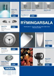
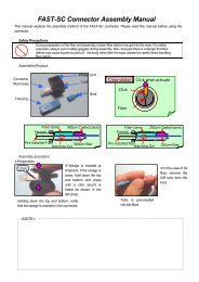
Light engineering specifications<br />
Light distribution characterised by average direct luminance 60° from the vertical.<br />
Efficiency<br />
Average series efficiency >74%.<br />
Materials<br />
PVD aluminium. The Physical Vapour Deposition treatment causes a surface microlayer<br />
of very pure (99.99% Al content) aluminium that allows optimum optical results<br />
and maximum efficiency. 2 μm oxide layer with no iridescence or micro-cracks.<br />
Manufacture<br />
Composed of longitudinal elements with double-parabolic profile and louvres with<br />
parabolic profile, closed at the top to improve total luminous efficiency and increase<br />
overall resistance.<br />
Application hints<br />
• premises where visual display units are in continuous use<br />
• free lay-out of the luminaires<br />
• provide for accurate surface light density distribution uniformity using a correct<br />
number of luminaires.<br />
Dark 60°
Reflector material characteristics<br />
Surface aluminium content % 99,99<br />
Surface finishing<br />
mirror finish<br />
Total reflection % 95<br />
Iridescence<br />
no<br />
Anodising oxide thickness<br />
2 μm<br />
Resistance to abrasion<br />
limited<br />
Louvres material characteristics<br />
Surface aluminium content % 99,99<br />
Surface finishing<br />
mirror finish<br />
Total reflection % 95<br />
Iridescence<br />
no<br />
Anodising oxide thickness<br />
2 μm<br />
Resistance to abrasion<br />
limited<br />
Light engineering specifications<br />
Light distribution characterised by average direct luminance lower than 200 cd/m 2 ,<br />
both lengthwise and crosswise, for observation angles greater than 65° from the<br />
vertical using 14W, 21W, 28W or 35W T5 lamps, and lower than 300 cd/m 2 for observation<br />
angles greater than 65° from the vertical using 24W, 39W, 54W or 80W T5<br />
lamps.<br />
Efficiency<br />
Average series efficiency >70%.<br />
Materials<br />
PVD aluminium. The Physical Vapour Deposition treatment causes a surface microlayer<br />
of very pure (99.99% Al content) aluminium that allows optimum optical results<br />
and maximum efficiency. 2 μm oxide layer with no iridescence or micro-cracks.<br />
Manufacture<br />
Composed of longitudinal reflectors and double-parabolic louvres closed at the bottom<br />
with triple faceting pattern.<br />
Application hints<br />
• premises where visual display units are in use<br />
• lLuminaire lay-out should be carefully planned<br />
• provide for accurate surface light density distribution uniformity using a correct<br />
number of luminaires.<br />
TM5 DK<br />
89<br />
Dark 60° optic<br />
TM5 DK optic
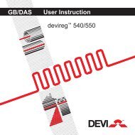
False-ceiling/recessed luminaire compatibility<br />
Reading key<br />
■ Recommended installation<br />
❍ Permissible installation<br />
With panels<br />
and exposed<br />
framework<br />
With panels and<br />
semi-concealed<br />
framework<br />
Plaster<br />
Plastered<br />
cardboard<br />
Framework with exposed<br />
or coated extruded<br />
aluminium T-profiles<br />
Walkable solid and<br />
coated-polyurethane<br />
modular<br />
With metal panels<br />
and clip-in<br />
retention either<br />
concealed or<br />
resting on exposed<br />
T supports<br />
FALSE CEILING TYPES<br />
Symmetrical<br />
open<br />
staves<br />
Asymmetrical<br />
closed<br />
staves<br />
RECESSED MODELS<br />
page<br />
T15<br />
600 mm<br />
modular symmetrical<br />
T24<br />
600 mm<br />
modular symmetrical<br />
Frameless solid<br />
600 mm modular<br />
Special customised<br />
executions<br />
1m modular<br />
Inspectable solid<br />
visible<br />
600 mm<br />
modular symmetrical<br />
concealed<br />
Width 30 mm<br />
Pitch 50 mm<br />
Height 16 mm<br />
Width 50 mm<br />
Pitch 50 mm<br />
Height 16 mm<br />
Width 80 mm<br />
Pitch 100 mm<br />
Height 16 mm<br />
Sharpedge<br />
staves<br />
Width 130 mm<br />
Pitch 150 mm<br />
Height 16 mm<br />
Width 180 mm<br />
Pitch 200 mm<br />
Height 16 mm<br />
Width 30 mm<br />
Pitch 50 mm<br />
Height 38 mm<br />
Width 50 mm<br />
Pitch 50 mm<br />
Height 38 mm<br />
Width 30 mm<br />
Pitch 50 mm<br />
Height 16 mm<br />
Width 50 mm<br />
Pitch 50 mm<br />
Height 16 mm<br />
Roundedge<br />
staves<br />
Width 84 mm<br />
Pitch 100 mm<br />
Height 16 mm<br />
Width 135 mm<br />
Pitch 150 mm<br />
Height 16 mm<br />
Width 185 mm<br />
Pitch 200 mm<br />
Height 16 mm<br />
Width 30 mm<br />
Pitch 50 mm<br />
Height 16 mm<br />
Sharpedge<br />
staves<br />
Width 80 mm<br />
Pitch 100 mm<br />
Height 16 mm<br />
Width 180 mm<br />
Pitch 200 mm<br />
Height 16 mm<br />
Roundedge<br />
staves<br />
Width 84 mm<br />
Pitch 100 mm<br />
Height 16 mm<br />
PURA INCASSO 360 ■<br />
ZETA 55 GP - 65 GP 366 ■ ■ ■ ■ ■ ■ ■<br />
ZETA 54 D2 376 ■ ❍ ■ ■ ■ ❍ ■ ❍ ■ ■ ■ ■ ■ ■<br />
ZETA RIFLESSA 378 ■ ■ ■ ■ ■ ■<br />
ZETA LL 380 ■ ■ ■ ■ ■ ■<br />
ZETA UP 382 ■ ■<br />
Modular false ceilings with mineral fibre or plastered<br />
cardboard panels and exposed framework<br />
Walkable solid or inspectable modular false ceilings,<br />
made of 1m polyurethane foam panels coated in prepainted<br />
or plasticized steel or aluminium<br />
Modular false ceilings with mineral fibre or plastered<br />
cardboard panels and semi-concealed framework<br />
Modular false ceilings with metal panels and clip-in retention<br />
either concealed or resting on T supports<br />
Frameless solid plaster or<br />
plastered cardboard false ceilings<br />
Symmetrical open staves<br />
Extruded aluminium exposed or coated T-profiles<br />
Asymmetrical closed staves
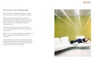
ZETA 55 - ZETA 65 (products on page 53-61)<br />
cross section<br />
longitudinal section<br />
cross section<br />
longitudinal section<br />
cross section<br />
longitudinal section<br />
600 mm modular false ceilings with metal panels and clip-in framework<br />
made of galvanised steel ('elios') tubes in dia.16 mm – the luminaire<br />
is secured using unversal brackets (MEC1068)<br />
600 mm modular false ceilings with metal panels and clip-in framework<br />
– the luminaire is secured using brackets (MEC1068)<br />
600 mm modular false ceilings with metal panels and clip-in framework<br />
– the luminaire is secured using brackets (MEC1068)<br />
cross section<br />
longitudinal section<br />
cross section<br />
longitudinal section<br />
600 mm modular false ceilings with metal panels and T24 exposed framework<br />
– the luminaire rests on supports; with T15 exposed framework<br />
– the luminaire is secured using safety brackets (MEC1068)<br />
600 mm modular false ceilings with mineral fibre or plastered cardboard panels<br />
and T24 exposed framework – the luminaire rests on supports; with T15 exposed<br />
framework – the luminaire is secured using safety brackets (MEC1068<br />
cross section<br />
TC-L lamp<br />
longitudinal section<br />
T8 lamp<br />
longitudinal section<br />
cross section<br />
TC-L lamp<br />
longitudinal section<br />
T8 lamp<br />
longitudinal section<br />
cross section<br />
cross section<br />
600 mm modular false ceilings with metal panels<br />
and clip-in framework made of galvanised<br />
steel ('elios') tubes ø 22 mm – the luminaire is<br />
secured using universal brackets (MEC1068)<br />
Non-inspectable frameless solid<br />
plastered cardboard false ceilings -<br />
the luminaire protrudes and is supported<br />
by the basket (MEC1283)<br />
Non-inspectable frameless solid<br />
plastered cardboard false ceilings -<br />
the luminaire is mounted flush to<br />
the ceiling and supported by the basket(MEC1283)<br />
600 mm modular false ceilings with protruding metal panels and T15 or T24 exposed framework – the luminaire<br />
is secured using brackets (MEC1068) - only versions with TC-L or T5 lamps<br />
600 mm modular false ceilings with mineral fibre or plastered cardboard panels and T15 or T24 semi-concealed<br />
framework – the luminaire is secured using brackets (MEC1068) - only versions with TC-L or T5 lamps<br />
cross section<br />
cross section<br />
cross section<br />
cross section<br />
cross section<br />
cross section<br />
Framework with exposed or coated extruded aluminium T-profiles, flush-mounted luminaires, luminaires resting on supports with height difference, also in customised execution - Do<br />
not hesitate to contact our Technical Department to investigate false-ceiling compatibility and dimensional/technical data.<br />
91<br />
False-ceiling/recessed luminaire compatibility
Electrotechnics<br />
Fluorescent discharge lamps<br />
Electrical system should be sized according to <strong>app</strong>arent power “A” (equal to the product of supply voltage by the absorbed power). With some equipment (incandescent<br />
lamps, resistance furnaces, etc.) all absorbed <strong>app</strong>arent power is used as active power “P”, with others (fluorescent lamps, motors, transformers, etc.), part of the absorbed<br />
<strong>app</strong>arent power, indicated as reactive power “Q”, is used to excite the magnetic circuits. Consequently it cannot be used as active power to perform the work.<br />
The ratio of active power to <strong>app</strong>arent power represent the power factor “cosϕ” (to be read as “cos fi”), i.e. the discrepancy between voltage and current when the equipment<br />
absorbs reactive power.<br />
cosϕ = ___ P<br />
A<br />
Companies supplying electric energy foresee increased fees for users with a low power factor. This is why it is required that all system are power-improved to a cosϕ >0,9<br />
Characteristics of power factor correction condensers<br />
for fluorescent lamps with electromagnetic ballast<br />
Power (W) Connected in parallel Connected in series<br />
1x18 4,5 μF x 250V 2,7 μF x 450V capacitative<br />
2x18 4,5 μF x 250V 2,7 μF x 450V capacitative<br />
(one ballast)<br />
1x36 4,5 μF x 250V 3,4 μF x 450V capacitative<br />
2x36 9 μF x 250V 3,4 μF x 450V DUO<br />
1x58 7 μF x 250V 5,3 μF x 450V capacitative<br />
2x58 14 μF x 250V 5,3 μF x 450V DUO<br />
Capacitative circuit without improved power<br />
factor<br />
Circuit with improved power factor and condenser<br />
connected in parallel<br />
Inductive circuit without improved power<br />
factor<br />
“DUO” circuit with improved power factor<br />
(power factor improvement is obtained by<br />
matching an inductive circuit to a capacitative<br />
circuit)<br />
Lamp type Power lamp Power absorbed (W) by the ballast-lamp circuit<br />
(categories) at 50 Hz (W) corresponding to the different class<br />
A1 A2 A3 B1 B2<br />
Tubular lamp 15 _
Electronic ballasts for fluorescent lamps<br />
• Average energy saving equal to 25%<br />
• Immediate lighting, simultaneous in case of several lamps, without any noise<br />
• Low temperature switch on<br />
• In low temperatures, higher luminous flux that can be obtained with conventional<br />
system (in some cases also 100%)<br />
• Buzz- free operation<br />
• No flickering effect<br />
• No lamp end blackening<br />
• No stroboscopic effect<br />
• No radio noise and very small magnetic fields<br />
• Low operating temperatures with reduced thermal load on the system<br />
• Non-pulsing “continuous” light as in the traditional 50Hz type, and therefore<br />
“not tiring”.<br />
• Low sensitivity to mains voltage surges<br />
• High power factor (cosϕ)<br />
• Light control option in the dimmer version<br />
• Selection of “dc” or “ac” versions<br />
• Automatic shut-off at lamp exhaustion and automatic reset after replacement<br />
Electronical ballasts with dimmers<br />
for fluorescent lamps<br />
Ballasts with dimmers for fluorescent lamps Ballasts with dimmers not only offer<br />
the typical advantages of electronic ballasts as mentioned above, but also<br />
the possibility of adjusting the light flow emitted by the lamps from 1% to<br />
100% depending on the lamps and models.<br />
We recommend, whenever possible, to use the less expensive odels with a limited<br />
adjustment range (from 10-20% to 100%).<br />
This type of adjustment range allows to significantly increase the system’s<br />
energy saving, difficult to quantify since it depends on several<br />
factors, such as:<br />
• geographical position<br />
• room orientation and position<br />
• glass panel size and type<br />
• reflection factors in environment<br />
• cleanliness of glass surfaces<br />
Depending on the model, adjustment takes place by means of:<br />
• a continuous voltage which may vary from 0 to 10 Vc.c<br />
• a digital signal<br />
• management system (EIB, LON, DALI)<br />
DALI SYSTEM<br />
DALI is the new digital interface standard for electronic ballasts with dimmers<br />
and describes the communication protocol with the electronic ballasts, but not<br />
the control systems. DALI is not a bus system, but the definition of a new interface!<br />
EIB (European Installation Bus) and LON (Local Operating Network) are<br />
systems which completely cover all the necessary functions to manage a building.<br />
These technologies not only allow to control lighting, but also heating<br />
and air conditioning systems as well as safety systems. DALI (Digital Addressable<br />
Lighting Interface) is designed to manage the light of an environment to<br />
be lit, but, if necessary, it may also be incorporated into the management<br />
systems of building of a superior level through the EIB and LON interfaces.<br />
Developed both to control light scenarios and to be interfaced with building<br />
management, DALI offers a very flexible sophisticated light control system at<br />
low installation costs.<br />
DALI’s crux is the on/off and adjustment combination through the control connections<br />
with the possibility of controlling each single ballast. This allows to independently<br />
control lighting equipment belonging to a single control circuit by<br />
re-configuring the installation without modifying the system.<br />
Main advantages:<br />
• The polarity of the control lines is irrelevant for electronic ballasts.<br />
• It is possible to use the existing wiring both for the power supply and for the control<br />
lines.<br />
• Digital technology ensures communication without any interference.<br />
• The lighting and adjustment circuits are independent from the wiring layout and<br />
thus offer a high flexibility; the control connection is low voltage without polarity<br />
in order to eliminate any wiring error.<br />
• It is possible to control single or groups of lighting devices.<br />
• During the design stage, it is not necessary to worry about combining lighting devices<br />
with relative switches, control panels, sensors, etc. This type of combining<br />
may occur at a later time and may be modified at any time without any modification<br />
to wiring.<br />
• It is possible to add on new sensors and new interfaces without having to modify<br />
the wiring of the lighting devices, all one has to do is to select the devices to be<br />
controlled and re-program the system.<br />
• DALI electronic ballasts may belong to more than one group at the same time.<br />
• The values attributed to lighting scenarios and group assignment may be memorized<br />
in the electronic ballasts (needs a definitely lower number of components than<br />
that required by a 1-10 Vc.c. system).<br />
• The feedback from the electronic ballast helps to identify: operating conditions,<br />
light on/off, current value of light output, lamp not working.<br />
• It is possible to foresee special settings to define the speed to change lighting levels<br />
or behavior in case of a system malfunction.<br />
• When a scenario is recalled, all the DALI electronic ballasts automatically position<br />
themselves to the set values.<br />
• Different lighting scenarios for different visual tasks or to create different “environments”<br />
may be memorized in the electronic ballasts.<br />
• Adjustment from 1 to 100% (depending on the type of electronic ballast)<br />
Economic advantage calculation for <strong>app</strong>lication over an area of <strong>app</strong>roximately 2400 sq. m.<br />
with an average illuminance of 580 lux<br />
Lamp. Life: 10.000 hrs with electromagnetic ballast, 18.000 hrs with electronic ballast<br />
Energy cost: 0,14 €/kWh Yearly operation: 4.000 hrs Maintenance: lamp cost + replacement cost = 5.00 Euros each<br />
initial investment difference 2607<br />
Amortization = ______________________________________________________ = _____________________ = 8 months<br />
monthly maintenance cost diff. + monthly energy saving diff. 302 + 15,48<br />
Elettromagnetico Elettronico Differenza %<br />
Light density level lux 640,00 615,00 -25,00 -3,9<br />
No. of 2x58w nr. 209,00 209,00 0,00 0,0<br />
Full lamp power (ballast EEI-B2) W 134,00 110,00 -24,00 -17,9<br />
Total power absorbed by the system KW 29,47 22,99 6,48 -22,0<br />
Yearly energy cost: system (4,000 h x 0.12 Euro/KWh) € 16.503,20 12.874,20 -3.628,80 -22,0<br />
Monthly energy cost € 1.375,27 1.072,87 302,40 -22,0<br />
Initial investment € 13.224,06 15.831,12 -2.607,07 19,7<br />
Months of lamp duration (lamp duration 4,000 h) months 30,00 54,00 24,00 80,0<br />
Total maintenance cost € 1.045,00 1.045,00 0,00 0,0<br />
Monthly maintenance cost €/month 34,83 19,35 15,48 -44,4<br />
Electronic ballasts<br />
Lamp Ballast System<br />
P Φ P EEI P Φ/P<br />
(W) (lm) (W) system (W) (lm/W)<br />
T8 16 1.300 3 A2 19 68,42<br />
T8 32 3.200 3 A2 35 91,4<br />
T8 50 5.000 5 A2 55 91<br />
T5 14 1.200 3 A2 17 70,6<br />
T5 21 1.900 3 A2 24 79,2<br />
T5 24 1.750 3 A2 27 64,8<br />
T5 28 2.600 3 A2 31 83,9<br />
T5 35 3.300 3 A2 38 86,8<br />
T5 39 3.100 3 A2 42 73,8<br />
T5 49 4.300 5 A2 54 79,6<br />
T5 54 4.450 5 A2 59 75,4<br />
T5 80 6.150 6 A2 86 71,5<br />
Note: This calculation does not take into account costs for exhausted lamp disposal<br />
The greater number of luminaires with electronic ballasts compensates for the lower light flux<br />
emitted (5000 lm vs. 5200 lm) from the lamps with this type of ballast.<br />
93<br />
Electrotechnics
Electrotechnics<br />
Emergency lighting<br />
1.1 Generalities<br />
Emergency lighting is intended for operation when standard lighting fails (UNI EN<br />
1838 Lighting engineering <strong>app</strong>lication - Lighting emergency) and it is divided into the<br />
following types:<br />
• Back up lighting that, in case of failure of standard light sources, should allow to go<br />
on or, where possible, achieve a work cycle in progress under safety conditions.<br />
• Safety lighting that, in case of accidental lack standard light sources, should be provided<br />
to identify escape routes and guide through them also under extremely critical<br />
conditions<br />
• In turn divided into:<br />
– Lighting of escape routes<br />
– Anti-panic lighting<br />
– Lighting of high risk activities<br />
1.2 Installation<br />
The safety system must be independent of any other electrical system on the premises<br />
1.3 Intervention<br />
The automatic intervention time for safety lighting goes from the moment that the ordinary<br />
lighting power system fails and the moment in which safety sources are enabled.<br />
Regulations identify automatic intervention safety power supply in five different<br />
categories, depending on the time required for them to become available:<br />
1) Continuity power supply, thanks to which the lighting devices remain fed and therefore<br />
permanently lit, that is to say without a break.<br />
2) Power supply with a very brief interruption, no higher than 0.15 s<br />
3) Power supply with a brief interruption, higher than 0.15 s but not higher than 0.5 s,<br />
4) Power supply with a medium interruption, higher than 0.5 s but not higher than 15<br />
s<br />
5) Power supply with a long interruption, higher than 15 s.<br />
The choice of the type of interruption must be made according to how the premises<br />
are to used, that is to say in compliance with the requirements of legislative texts or<br />
specific technical regulations.<br />
A typical example of safety lighting devices which always remain lit is that of cinemas<br />
and theatres, where lighting, of escape routes outside the auditorium and safety lighting<br />
inside the auditorium, is permanent.<br />
Regulation UNI EN 1838 requires that along escape routes, light sources must reach at<br />
least 50% of their light performance within 5 s and 100% within 60 seconds.<br />
1.4 Autonomy<br />
Devices may be generally supplied with emergency groups with an autonomy of 1 or 3<br />
hours.<br />
The choice of the autonomy of a safety lighting system, unless otherwise specified by<br />
regulations (CEI 64-4, CEI 64-8, CEI 64-50, etc.) or legislation (Legislative Decrees,<br />
Ministerial Decrees, etc.), must be in relation to the time required to evacuate the premises,<br />
while for a back up system, the choice depends on the time needed to end a<br />
work cycle.<br />
All batteries, either Lead or NiCd, suffer from a progressive loss of power during their<br />
life.<br />
This loss can be accelerated in case of long storage or operation in high<br />
temperature.<br />
Autonomous emergency luminaries must be fitted with batteries that need not to be<br />
Room type reference documents prescription autonomy<br />
Archives CEI 64-8 DPR 418 30.06.95 5 lux 1h<br />
Garages UNI EN 81/1-7.89 DM 236-14.06.89 5 lux unspecified<br />
Garages without ramp CMI 29.08.95 CEI 64-8 Lighting obbligation 1 h<br />
Unspecified values (5 lux)<br />
Parking garage DM 01.02.86 CEI 64-8 5 lux unspecified ( 1 h)<br />
Firms with employed DLgs 626-19.09.94 DM 08.03.85 Lighting obbligation unspecified<br />
CEI 64-8 High risk areas: 10% ordinary lighting ( 1 h)<br />
Libraires DPR 418-30.06.95 CEI 64-8 5 lux 1 h<br />
Electrical cabs DPR 547/55 art. 341 Lighting obbligation unspecified<br />
Unspecified values (5 lux) ( 1 h)<br />
Private hospitals DM 08.03.85 CEI 64-8 Lighting obbligation 3 h<br />
CEI 64-4 Unspecified values (5 lux) ( 1 h with back up lighting)<br />
Home for aged DM 08.03.85 CEI 64-4 Lighting obbligation 3 h<br />
CEI 64-8 DDF 29.07.39 Unspecified values (5 lux) ( 1 h with back up lighting)<br />
Shop centres CEI 64-8 CEI 64-51 unspecified 1h<br />
Cinemas DM 08.03.855 CEI 64-8 5 lux 1 h<br />
DM 19.08.96<br />
Colleges DM 08.03.85 CEI 64-8 5 lux 1 h<br />
DM 26.08.92<br />
Discoteques DM 08.03.85 CEI 64-8 5 lux 1 h<br />
DM 19.08.96<br />
Expositions DM 569 – 20.05.92 CEI 64-8 Lighting obbligation unspecified<br />
Unspecified values (5 lux) ( 1 h)<br />
Hotels DM 08.03.85 DM 09.04.94 5 lux 1 h<br />
Rule 406 – 18.07.80 CEI 64-8<br />
Sporting premises DM 08.03.85 CEI 64-8 5 lux 1 h<br />
DM 19.08.96<br />
Working areas DLgs 626 – 19.09.94 CEI 64-8 Lighting obbligation unspecified<br />
DPR 547 – 1955 art. 31 Unspecified values (5 lux) ( 1 h)<br />
Public performance areas DM 08.03.85 DM 19.08.96 2 lux ambienti aperti al pubblico 1 h<br />
CEI 64-8<br />
5 lux porte e scale<br />
Undergrounds UNI EN 81/1 july 1989 1 W 1 h<br />
Exhibitions DM 569 – 20.05.92 Lighting obbligation unspecified<br />
Unspecified values (5 lux) ( 1 h)<br />
Museums DM 569 – 20.05.92 CEI 64-15 2 lux public environment 1h<br />
CEI 64-8<br />
5 lux doors and stairs<br />
Shops DM 08.03.85 CMI 75 – 03.07.67 Lighting obbligation unspecified<br />
CEI 64-8 Unspecified values (5 lux) ( 1h)<br />
Workshops DPR 547/55 art. 31 CEI 64-8 Lighting obbligation unspecified<br />
DL 626 – 19.09.94 Unspecified values (5 lux) ( 1h)<br />
Hospitals DM 08.03.85 DDF 29.07.39 Lighting obbligation 3 h<br />
CEI 64-8 CEI 64-4 Unspecified values (5 lux) ( 1h with back up lighting)<br />
Hostels DM 08.03.85 DM 09.04.94 5 lux 1 h<br />
CEI 64-8 Rule 406 – 18.07.80<br />
Clinics DM 08.03.85 DDF 29.07.39 Lighting obbligation unspecified<br />
CEI 64-8 CEI 64-4 Unspecified values (5 lux) ( 1 h)<br />
Tourist and DM 08.03.85 DM 09.04.94 5 lux 1 h<br />
hotel activies CEI 64-8 Rule 406 – 18.07.80
eplaced for at least 4 years of current operation (CEI EN 60 598-2-22:1999-04<br />
par.22.6.8).<br />
Battery replacements required when the luminaire does no longer meet declared duration<br />
performance.<br />
1.5 Recharging<br />
• 6 h for premises used for medical purposes autonomy must be guaranteed after 6 h<br />
(cei 64-4 par. 4.1.01)<br />
• 12 h –for schools<br />
– for private and public entertainment premises<br />
– for tourist-hotel activities<br />
• 24 h whenever not differently required (CEI EN 60 598 2-22.1:1999-04 par. 22.19.1)<br />
The emergency groups supplied by NORLIGHT S.p.A. are intended for a 24h recharge.<br />
A 12h recharge is possible by using the groups with a 3 hour autonomy as if they had<br />
a 1h autonomy (in 12 h the batteries are charged at 50%, but since they are expected<br />
to last 3h, they can ensure the expected 1 hour autonomy).<br />
No emergency group is available with a 3h autonomy to be recharged in 12h.<br />
1.6 Maintenance<br />
• First installation inspections<br />
– Operation (turning on or off in case of a power failure through controls, if present)<br />
– Lighting level<br />
– Autonomy<br />
– Line independence<br />
– Equipment positioning<br />
– Inhibition controls (if present)<br />
• Periodical inspections<br />
– every time the premises are opened (only for public premises); operation of the<br />
emergency system<br />
– every six months: check operation of the emergency system and the autonomy<br />
– every 4 years:<br />
a) check operation of the emergency system, autonomy, lighting level<br />
b) replace batteries.<br />
1.7 Lighting<br />
The chart on the page here above indicates the light values and autonomy of emergency<br />
systems required by legislation or by regulations for various types of premises.<br />
It is important to point out that emergency lighting should not be bound to fixed values,<br />
but should also consider the light values during normal operation, since the eye<br />
requires a longer time to adjust to big differences, and could therefore be a cause of<br />
panic.<br />
1.8 Regulations<br />
Regulations for devices and components<br />
CEI EN 60 598-1-22<br />
Lighting equipment – Part 1. General requirements and tests<br />
CEI EN 60 598-1-22<br />
Lighting equipment – Part 2. Particular requirements<br />
CEI EN 60 285<br />
NiCd accumulators. Individual rechargeable air- and water-tight elements.<br />
Regulations for systems<br />
UNI EN 1838<br />
Lighting engineering-emergency lighting <strong>app</strong>lication<br />
CEI 64-8<br />
User electric systems with a nominal voltage no higher than 1,000 V a.c.<br />
Emergency devices with 1,500 V d.c.<br />
CEI 64-4<br />
Electric system in premises used for medical purposes<br />
CEI 64-50<br />
Residential buildings – Guide for integrating into the building auxiliary and telephone<br />
user electric systems.<br />
CEI 64-15<br />
Electric systems in historic and/or artistic buildings.<br />
Meeting rooms DM 08.03.85 CEI 64-8 5 lux 1 h<br />
DM 19.08.96<br />
Schools DM 08.03.85 CEI 64-8 5 lux 30 minuti<br />
DM 26.08.92<br />
Theatres CMI 16 – 15.02.51 DM 08.03.85 5 lux 1 h<br />
CEI 64-8 DM 19.08.96<br />
Offices DM 08.03.85 CEI 64-8 Lighting obbligation unspecified<br />
DLgs 626 – 19.09.94 Unspecified values (5 lux) ( 1 h)<br />
Characteristics of the electronic assemblies (inverter + battery) for fluorescent lamps (tubular, compact, circular)<br />
• Immediate operation upon mains failure<br />
• Operation both with permanent and non permanent light<br />
• High efficiency and reduced heat loss<br />
• Reliability<br />
• No blackening and long- lasting lamps • High temperature NiCd accumulators (CEI EN 60 285)<br />
• Recharging indicator (red LED) in full view<br />
• Protection device against prolonged discharges<br />
• Remote control disabling • Inverter in compliance with CEI EN 60 924, CEI EN 60 925 and CEI EN 60 929<br />
• Supply voltage: 230V/50-60 Hz<br />
• Supply current: 40 mAmp max, cosϕ0.9<br />
• Operating frequency 20-30 kHz<br />
• Max inverter to lamp distance: 2 m<br />
• 12 h or 24 h recharging period depending on the model<br />
(in any case, the first time they must be completely<br />
discharged and then recharged for about 48 h)<br />
Technical characteristics<br />
Flow as a % of the nominal flow of fluorescent lamps of the various types of emergency groups<br />
Lamp Powers Base 1h model 3h model<br />
autonomy % flow autonomy % flow<br />
14W G5 1h 25% 3h 30%<br />
T5-FH<br />
21W G5 1h 16% 3h 20%<br />
24W G5 1h 14% 3h 14%<br />
35W G5 1h 12% 3h 12%<br />
24W G5 1h 15% 3h 15%<br />
39W G5 1h 7% 3h 8%<br />
T5-FQ 49W G5 1h 7% 3h 7%<br />
54W G5 1h 7% 3h 7%<br />
80W G5 1h 6% 3h 6%<br />
18W G13 1h 16% 3h 14%<br />
T8 36W G13 1h 30’ 12% 3h 9%<br />
58W G13 1h 8% 3h 7%<br />
18W 2G11 1h 18% 3h 16%<br />
TC-L<br />
24W 2G11 1h 16% 3h 15%<br />
36W 2G11 1h 30’ 12% 3h 9%<br />
55W 2G11 1h 8% 3h 7%<br />
18W G24q-2 1h 18% 3h 12%<br />
26W G24q-3 1h 12% 3h 9%<br />
TC-D 32W GX24q-3 1h 30’ 12% 3h 9%<br />
42W GX24q-4 1h 13% 3h 7%<br />
57W GX24q-5 1h 5% 3h 5%<br />
The emitted flux values shown above are indicative only and depend on the models.<br />
For special requirements please contact the Technical Department of NORLIGHT S.p.A.<br />
95<br />
Electrotechnics
Protection level<br />
Equipment’s protection level (CEI EN 60 529)<br />
First digit (from 0 to 6 or letter X)<br />
Protection against entry of solid matter<br />
Second digit (from 0 to 8 or letter X)<br />
Protection against entry of water<br />
Possible additional letter (A,B,C,D)<br />
Protection against access to dangerous parts<br />
Possible additional letter (H, M, S, W)<br />
First digit (from 0 to 6 or letter X) unprotected protected against protected against protected against protected against protected against totally protected against<br />
Protection against entry solid matter whose size solid matter whose size solid matter whose size solid matter whose size dust dust<br />
of solid matter is 50 mm is 12mm is 2,5 mm is 1 mm<br />
0 1 2 3 4 5 6 7 8<br />
Second digit (from 0 to 8 or letter X) unprotected protected against protected against drop protected against rain, protected against protected against protected against protected against protected against<br />
Protection against water entry vertical drop of water droplets with a with a maximum water sprays coming water jets powerful water jets the effects of temporary continuous immersion<br />
of water droplets maximum inclination of 15° inclination of 60° from any direction immersion (with depth indication)<br />
A B C D H M S W<br />
Possible additional battery Protected against access Protected against access Protected against access Protected against access High voltage equipment Tested against harmful Tested against harmful Suitable for use in the<br />
with the back of one’s hand with one’s finger with a tool of a wire effects due to water effects due to water specified environmental<br />
entry, when the entry, when the conditions and equipped with<br />
equipment’s moving parts equipment’s moving parts additional protective measures<br />
are in motion are not in motion or procedures
Chemical Resistance Table<br />
This table shows the resistance to chemicals of materials generally used. Data is referred<br />
to an ambient temperature of <strong>app</strong>roximately 22°C. Some of the industrial environments<br />
where corrosion is likely to take place are:<br />
- Chemical and oil plants<br />
- Food plants (dairies, butcheries, breweries, etc.)<br />
- Chemical laboratories<br />
- Agriculture<br />
- Collectivity kitchens<br />
- Painting plants<br />
- Plants and workshops with mineral oil vapours<br />
- Tinning plants<br />
and so on.<br />
Shock resistance: IK code (CEI EN 50 102)<br />
The IK code is followed by a numeric group which identifies the value of the shock<br />
energy (see chart) that the casing must withstand for 5 consecutive impacts, but for<br />
no more than 3 times in the same place, unless differently specified.<br />
The test equipment may work according to 3 principles:<br />
• spring hammer: weight pushed by a calibrated spring;<br />
• pendulum hammer: weight hinged on a rotation axis through an arm which controls<br />
its path;<br />
• vertical hammer: weight which falls freely on the test surface without bouncing<br />
and from a specific height<br />
The shock element consists in a steel body and an insert destined to the shock with<br />
the object to be tested.<br />
CODE<br />
ENERGY<br />
IK00<br />
No protection<br />
IK01<br />
0,15 J<br />
IK02<br />
0,20 J<br />
IK03<br />
0,35 J<br />
IK04<br />
0,50 J<br />
IK05<br />
0,70 J<br />
IK06<br />
1,00 J<br />
IK07<br />
2,00 J<br />
IK08<br />
5,00 J<br />
IK09<br />
10,00 J<br />
IK10<br />
20,00 J<br />
If 20 J should still not be sufficient, the Regulation suggests to use 50J as the higher<br />
level<br />
Chemicals Stainless Steel Aluminium Polyester Methacrylate Polycarbonate<br />
Acetone - - -<br />
Aliphatic hydrocarbons - - -<br />
Alcohol up to 30% - - -<br />
Alcohol concentrated - -<br />
Ammonia at 25% - -<br />
Accumulator acid <br />
Aniline - - -<br />
Aromatic hydrocarbons - -<br />
Ether - -<br />
Ethyl acetate - - -<br />
Gasoline <br />
Benzol - - -<br />
Beer <br />
Blood <br />
Bromic acid - - - -<br />
Chloroform - - -<br />
Chlorophenol - - -<br />
Diesel fuels <br />
Dioxane - -<br />
Acetic acid up to 5% <br />
Acetic acid up to 30% - - <br />
Glycerol <br />
Glycol <br />
Glysantin antifreeze <br />
Carbon dioxide <br />
Carbon monoxide <br />
Caustic lime - <br />
Sodium chloride solution <br />
Ketones - - -<br />
Lysol - - -<br />
Sea water <br />
Methylene chloride - - -<br />
Methanol - - -<br />
Metal salts and their liquid solutions - <br />
Caustic soda 2% - <br />
Caustic soda 10% - - <br />
Petroleum ether <br />
Pyridine - - -<br />
Phenol - - -<br />
Nitric acid up to 10% - <br />
Nitric acid 10% to 20% - <br />
Nitric acid over 20% - - -<br />
Hydrochloric acid up to 20% - - <br />
Hydrochloric acid over 20% - <br />
Sulphuric acid up to 50% - - <br />
Sulphuric acid up to 70% - - <br />
Sulphuric acid over 70% - - - - -<br />
Sulphurous acid up to 5% -<br />
Hydrogen sulphide <br />
Soaped water <br />
Sodium carbonate - <br />
Synthetic lyes <br />
Turpentine oil <br />
Carbon tetrachloride - -<br />
Water up to 60°C <br />
Hydrogen dioxide up to 40% - - <br />
Hydrogen dioxide over 40% - <br />
Xylol - - -<br />
Dimethylbenzene - - -<br />
Minerals oil - -<br />
= resistant = relatively resistant - = non resistant<br />
97<br />
Shock resistance and resistance to chemical agents
Self-extinction capability of plastic materials<br />
American standard UL 94<br />
American UL 94 standards are considered a common reference to indicate the degree<br />
of self-extinction of a plastic material.<br />
HB<br />
The test sample is in a horizontal position and the lighting flame may advance with<br />
the following characteristics:<br />
• at a speed lower than 76mm/min in samples less than 3 mm thick<br />
• at a speed lower than 38mm/min in samples more than 3 mm thick<br />
25.4<br />
76.2<br />
25.4<br />
45°<br />
Flame test<br />
Regulation CEI EN 60 598-1 (Par. 13.3.1)<br />
Materials to which it is <strong>app</strong>lied<br />
The parts of insulating material (excluding ceramic) which keep the power carrying<br />
parts in position must be subjected to the needle flame test.<br />
Test conditions (Publication IEC 695-2-2)<br />
• The test sample must be subjected to the flame in the area where high temperatures<br />
are most likely.<br />
• Duration of the test: 10 s<br />
• Sheet of paper, specified in 6.86 of ISO 4046 regulation, laid down horizontally<br />
200 mm under the test sample.<br />
Result of the tests<br />
After the flame is moved away, combustion<br />
must not continue for more than 30<br />
s, and any possible ignited drops must<br />
not set fire to neighboring parts or to the<br />
sheet of paper underneath the test sample.<br />
V0<br />
The test sample is in a vertical position and the flame goes out within 10 seconds<br />
without dripping<br />
V1<br />
The test sample is in a vertical position and the flame goes out within 30 seconds<br />
without dripping<br />
V2<br />
The test sample is in a vertical position and the flame goes within 30 second and<br />
dripping of the melted material is allowed<br />
5V<br />
This is the strictest classification, and entails two sets of tests:<br />
1 – a flame 127 mm long is <strong>app</strong>lied for 5 seconds to the test sample in a vertical<br />
position, this is repeated for 5 times, at the end the flame must go out within 60<br />
seconds. Any drop of melted plastic must not set fire to a piece of cotton placed<br />
under the test sample. The procedure must be repeated 5 times.<br />
2 – The above test is run on 3 test samples put in a horizontal position.<br />
At the end of the test the material is classified as follows:<br />
5VB if there are holes due to the procedure<br />
5VA if there is no hole due to the procedure<br />
The above self-extinction grades are always associated to a minimum material<br />
thickness.<br />
20°<br />
Glow Wire Test<br />
Regulation CEI EN 60 598-1 (Par. 13.3.2)<br />
Materials to which it is <strong>app</strong>lied<br />
The parts of insulating material (excluding ceramic) which do not keep active parts<br />
in position, but which provide protection against electric shock and parts of insulating<br />
material which keep SELV parts in place must be subjected to the glow wire test<br />
at 650°C.<br />
Test conditions (publication IEC 695-2-1)<br />
• Heat source: 4mm incandescent wire kept pressed to the test sample<br />
• Duration of the test: 30 s<br />
• Test temperature: 650°C<br />
Please note: other regulations also require temperatures of 750° C or 850° C.<br />
• A layer if flimsy paper laid down horizontally at 200±5 mm beneath the test sample.<br />
Result of the test<br />
After the wire is moved away, all the<br />
test sample’s flames and incandescent<br />
parts must extinguish within 30<br />
S, and any drop must not set fire to a<br />
single layer of flimsy paper lying beneath<br />
the test sample
Photometric quantities<br />
Luminous intensity I cd (candle)<br />
Fundamental photometric quantity in the International<br />
System. An intensity of 1 cd is the intensity of a source<br />
emitting monochromatic radiation:<br />
with a frequency v= 540x1012 Hz<br />
and a power = 1/683w<br />
in a 1 sr solid angle<br />
Colour rendering categories<br />
Quantity Symbol Unit of measure Description Relations Classification Ra index<br />
1A > 90 where<br />
1B 80 Ra 90 1 - Sunlight (>5.000 K)<br />
2 60 Ra 80 2 - Very white light (~4.000 K)<br />
3 40 Ra < 60 3 - Warm light (
Photometry<br />
Photometric curve<br />
The whole of the measures of luminous intensities emitted by a luminaire in all directions forms the “photometric solid “. Usually not all information regarding the<br />
photometric solid is given, but only as regards two vertical planes normal to each other that cross the optical center of the luminaire.<br />
Luminous intensity values represented in polar co-ordinates on a plane define a line that is called<br />
“photometric curve”. They are generally expressed as cd/Klm, i.e. referred to a source emitting a luminous flux equal to a 1000 lm.<br />
Luminaire classification according to luminous flux<br />
DIN 5040<br />
Luminaire photometric classification as per this Standard is composed of one letter<br />
and two figures (ex.: A60). The letter (A, B ,C, D, E) indicates the percentage of luminous<br />
flux emitted in the upper and lower hemispheres. The closer it is to the letter A,<br />
the higher is the percentage of the flux emitted in the lower hemisphere. The figures<br />
that follow refer to the flux directed onto the working plane and to the ceiling, respectively,<br />
in the typical configuration provided for by the Standard.<br />
UTE C71-121<br />
Luminaire photometric classification is composed of the efficiency in the lower hemisphere<br />
followed by a letter plus the efficiency in the upper hemisphere followed<br />
by another letter (ex.: 0.50 D+0.24 T). Letters range from “A” to “J” and represent<br />
the luminous flux percentage inside given solid angles. If the letter T is present, this<br />
means that part of the luminous flux is emitted into the upper hemisphere.<br />
CIBSE TM5<br />
Luminaire photometric classification is divided into ten categories (BZ1 to BZ10).<br />
Each category refers to the percentage of luminous flux emitted in the lower hemisphere<br />
that directly reaches the working plane in a standard configuration. This is<br />
why this classification also depends upon room index. For example, luminaires classified<br />
as BZ1 emit a greater amount of luminous flux onto the working plane than<br />
BZ2 to BZ10 luminaires.<br />
Isolux Curves<br />
These curves connect points on the plane having same surface light density E (lux).
Surface light density calculations using the CIE method<br />
The formula to calculate the number of luminaires to be installed in a system is as follows:<br />
where: E med = required average surface light density (in lux),<br />
C m = maintenance factor,<br />
Φ = lamp flux per luminaire (in lumens)<br />
C u = utilization coefficient that can be obtained from the table below, near room surface reflectance<br />
and room index (K)<br />
Room index K is given by<br />
dove:<br />
a = room width<br />
b = room length<br />
h u = luminaire distance from the working plane<br />
Example:<br />
1. Room: a = 8 m, b = 4 m, h = 3m, h lav = 0,85 m, E med = 350 lux, C m =0.85<br />
2. 2- Room reflectance values: ceiling = 70% - frieze = 70% - walls = 50% - working level = 30% (the table<br />
column for the luminaire is no. 7553)<br />
3. Selected luminaire: ERRE D100R DARK 60°, 2x36w<br />
4. Room index K is calculated as follows:<br />
K =<br />
5. The number of luminaries to be installed is:<br />
n <strong>app</strong> =<br />
n <strong>app</strong> = _________ E med·(a·b)<br />
C m·C u·Φ<br />
K =<br />
(a·b) _______<br />
h u·(a+b)<br />
8·4 ______________ = 1,25<br />
(3–0,85)·(8+4)<br />
350·(8·4)<br />
_________________ = 4<br />
0,85·0,513·6700<br />
Utilization factors<br />
Room reflectance values (ceiling, frieze, walls, working level)<br />
K 8773 7773 7771 7553 7551 7731 5551<br />
0.60 428 424 398 364 351 324 349<br />
0.80 489 483 449 423 405 380 403<br />
1.00 536 528 487 470 448 424 444<br />
1.25 577 567 519 513 484 463 479<br />
1.50 606 594 540 544 509 490 503<br />
2.00 647 633 568 589 545 530 538<br />
2.50 673 656 585 618 565 553 557<br />
3.00 690 672 595 638 578 568 570<br />
4.00 709 689 605 660 592 584 583<br />
5.00 721 699 611 674 599 593 589<br />
10.00 746 721 621 705 615 610 603<br />
20.00 760 733 627 724 624 621 611<br />
6<br />
6<br />
14<br />
12<br />
48<br />
14<br />
16<br />
12<br />
14<br />
10<br />
22<br />
18<br />
52<br />
28<br />
32<br />
22<br />
34<br />
26<br />
40<br />
36<br />
60<br />
44<br />
48<br />
30<br />
52<br />
44<br />
62<br />
54<br />
68<br />
58<br />
62<br />
40<br />
66<br />
60<br />
72<br />
72<br />
80<br />
72<br />
74<br />
48<br />
Reflectance coefficients<br />
Table showing reflectance values for<br />
different colors, as %. When using<br />
these values to identify the utilization<br />
coefficient you should round off the<br />
values and consider:<br />
7 where you find 70<br />
5 where you find 50<br />
Surface light density calculation using the “Point-by-Point” method<br />
This method, that is used to calculate surface light density in a certain point on the horizontal plane, is<br />
commonly known as “point-by-point” method. Its formula is:<br />
E p = ________ I p·cos 3 α<br />
h 2<br />
or<br />
E p = ________ I p·cosα<br />
d 2<br />
I<br />
d<br />
Ep = horizontal surface light density at point P (lux)<br />
lp = intensity in candles in the direction of the point in question<br />
α = angle between the luminaire vertical and the point in question<br />
h = distance of the light source from the plane where the surface light density is to be calculated<br />
d = distance of the source from the point where the surface light density is to be calculated<br />
h<br />
α<br />
P<br />
101<br />
Lighting engineering calculations
Glare<br />
When in the field of view there is a very high luminance, with respect to the field’s average luminance, a person’s visual capacity is decreased. This phenomenon is called<br />
“glare” and it occurs, for example, when at night we meet a car with its headlights on or when light sources, either direct or reflected, are within our field of observation.<br />
There are mainly two types of glare:<br />
• Disability glare which consists in an instantaneous deterioration of visual functions<br />
• Discomfort glare which manifests itself as a visual discomfort and not always causes strong visual inconveniences, but which, in time, causes visual problems, lower<br />
attention, more probabilities of error, poorer performance.<br />
Glare can be caused in two ways:<br />
• Direct glare<br />
It is caused by a luminance distribution which directly hits the observer’s eyes (light coming directly from a lamp or from lighting equipment)<br />
• Indirect glare<br />
It is caused by the reflecting image of the light source (naked light or equipment), from the surface of the visual display unit, from the walls or from particularly reflecting<br />
furniture.<br />
Indirect glare can be reduced as follows:<br />
• Paying attention to how lighting equipment and visual display units are arranged<br />
• using lighting equipment with an <strong>app</strong>ropriate luminance so as to avoid reflections on visual display units or objects<br />
• Using non-specular and non-reflecting surfaces in the work area<br />
• Using diffused indirect lighting to reduce contrast<br />
In designing lighting engineering quality systems, it is necessary to follow the indications of the following regulation:<br />
• UNI EN 12464-1:2002 Light and Lighting. Lighting of work places. (ed. otober 2004)<br />
The regulation gives the limits of the average luminaire luminance at elevation angles of 65° and above from the downward vertical, radially around the luminaires for<br />
work places where displays screens, which are vertical or inclined up to 15° tilt angle, are used.<br />
Screen classes in accordance with ISO 9241-7 I II III<br />
Screen quality good medium poor<br />
Average luminances of luminaires which are reflected in the screen 500 30°<br />
The illuminance of the immediate surrounding areas<br />
(UNI EN 12464-1:2002)<br />
The illuminance of immediate surrounding areas shall be related to the luminance of<br />
the task area and should provide a well-balanced luminance distribution in the field<br />
of view.<br />
The illuminance of the immediate surrounding areas may be lower than the task illuminance<br />
but shall not be less than the values given in the table beside.<br />
Task iluminance<br />
(lx)<br />
Illuminance of immediate<br />
surrounding areas (lx)<br />
> 750 500<br />
500 300<br />
300 200<br />
< 200 E task<br />
Uniformity: > 0.7 Uniformity: > 0.5
UGR method (CIE 117-1995)<br />
The UGR (Unfied Glare rating method) was developed by CIE (Commission International de l’Eclarage) to harmonize glare classification procedures throughout the<br />
world. The formula for calculating the UGT is<br />
where: L = luminance of luminous parts of each device in the observation direction (cd/m 2 )<br />
UGR = 8log ______ 0,25 ______ L2·ω<br />
Lb = background luminance (cd/m 2 )<br />
ω = solid angle of luminous parts of each device referred to the observer’s eye (sr)<br />
p = indicates the Guth position for each device<br />
The above formula has been reported only for propaedeutic purposes and to show how the UGR calculation is quite complex when executed by hand and it is therefore<br />
necessary to use computerized calculation programs to be able to evaluate it.<br />
While the Söllner curve method serves to evaluate the glare of a single device, the UGR method serves to evaluate glare characteristics of a lighting system keeping<br />
into the account the contribution of each lighting devices, of the ceiling and of the walls with reference to one observation point.<br />
UGR values are expressed between 10 (lack of glare) and 30 (disability glare). Once the point of observation is defined, the UGR calculation is executed automatically<br />
using the computerized calculation program.<br />
Working area<br />
UGR MAX<br />
Technical offices 16<br />
Offices which require computer work 19<br />
Industrial precision tasks 22<br />
Industrial medium precision tasks 25<br />
General industrial tasks 28<br />
L b p 2 CIBSE - Lighting Guide LG3. 1996<br />
“CIBSE” equipment classification according to luminance<br />
The English CIBSE regulation classifies equipment according to three classifications depending on the angle beyond which the luminance value is lower than 200 cd/m 2 .<br />
Luminance contrast is carried out on four main planes: 0-180°, 90°, 270°, 135°-315°, 225°-45°, considering the position of the observer’s eyes.<br />
CIBSE LG3 CAT 1 CIBSE LG3 CAT 2 CIBSE LG3 CAT 3<br />
The equipment is classified as CAT1 if starting<br />
from an observation angle of 55° with respect to<br />
the axis, the reflector’s luminance is less than<br />
200 cd/m 2 .<br />
55°<br />
The equipment is classified as CAT2 if starting<br />
from an observation angle of 65° with respect to<br />
the vertical axis, the reflector’s luminance is less<br />
than 200 cd/m 2 .<br />
65°<br />
The equipment is classified as CAT2 if starting<br />
from an observation angle of 75° with respect to<br />
the vertical axis, the reflector’s luminance is less<br />
than 200 cd/m 2 .<br />
75°<br />
The Visual Environment for Display Screen Use Introduction<br />
CIBSE - Lighting Guide 3: Addendum 2001<br />
The visual environment for display screen use<br />
The addendum 2001 must be read together with the previous 1996 edition.<br />
Considering the widespread market trend to specify the category “CAT” of the<br />
equipment without considering the current work environment in which it will be installed,<br />
the “category” system has been removed from the LG3 guide.<br />
In the future any specification relative to the characteristics of lighting equipment<br />
for use in premises with video display units, must be specifically defined by the designer<br />
or chosen by the supplier according to the information provided by the customer/user.<br />
Considering only the light distribution of each single lighting equipment, does not<br />
guarantee that a satisfying lighting system will be achieved and therefore in order<br />
for the designer to plan a system which satisfies the requirements of the LG3 guide,<br />
he must keep all the aspects (lighting uniformity, luminance distribution, type of activity,<br />
etc.) reported in the guide into consideration.<br />
103<br />
Glare
Suggested lighting UNI EN 12461-1:2002<br />
Room type, visual task or activity Em (lx) UGR Ra Room type, visual task or activity Em (lx) UGR Ra Room type, visual task or activity Em (lx) UGR Ra<br />
TRAFFIC ZONES AND GENERAL AREAS INSIDE THE BUILDINGS<br />
Traffic zones<br />
Circulation areas and corridors 100 28 40<br />
Stairs, elevators, travolators 150 25 40<br />
Loading ramps/bays 150 25 40<br />
Rest, infirmary and first aid rooms<br />
Canteens, pantries 200 22 80<br />
Rest rooms 100 22 80<br />
Rooms for physical exercise 300 22 80<br />
Cloakrooms, washrooms, bathrooms, toilets 200 25 80<br />
Sick bay 500 19 80<br />
Rooms for medical attention 500 16 90<br />
Control rooms<br />
Plan rooms /switches gear rooms 200 25 60<br />
Telex, mail, post room, switchboard 500 19 80<br />
Store rooms, cold stores<br />
Store and stockrooms 100 25 60<br />
Dispatch packing handling areas 300 25 60<br />
Storage rack areas<br />
Gangways: unmanned 20 - 40<br />
Gangways: manned 150 22 60<br />
Control stations 150 22 60<br />
INDUSTRIAL AND CRAFTSMAN ACTIVITIES<br />
Chemical, plastic and rubber industry<br />
Remote -operated processing installations 50 - 20<br />
Processing installations with limited 150 28 40<br />
manual intervention<br />
Constantly manned work places in 300 25 80<br />
processing installations<br />
Precision measuring rooms, laboratories 500 19 80<br />
Pharmaceutical production 500 22 80<br />
Tyre production 500 22 80<br />
Colour inspection 1000 16 90<br />
Cutting, finishing, inspection 750 19 80<br />
Electric industry<br />
Cable and wire manufacture 300 25 80<br />
Winding:<br />
- large coils 300 25 80<br />
- medium-sized coils 500 22 80<br />
- small coils 750 19 80<br />
Coil impregnating 300 25 80<br />
Galvanising 300 25 80<br />
Assembly work:<br />
- rough 300 25 80<br />
- medium 500 22 80<br />
- fine 750 19 80<br />
- precision 1000 16 80<br />
Electronic workshops, testing, adjusting 1500 16 80<br />
Food stuffs and luxury food industry<br />
Work places and zones in: 200 25 80<br />
- breweries, malting floor<br />
- for washing, barrel filling, cleaning, sieving, peeling<br />
- cooking in preserve and chocolate factories<br />
- work places and zones in sugar factories<br />
- for drying and fermenting raw tobacco,<br />
fermentation cellar<br />
Sorting and washing of products, milling, 300 25 80<br />
mixing, packaging<br />
Work places and critical zones in slaughter houses, 500 25 80<br />
butchers, dairies mills, on filtering floor<br />
in sugar refineries<br />
Cutting and sorting of fruit and vegetables 300 25 80<br />
Manufacture of delicatessen foods, kitchen work, 500 22 80<br />
manufacture of cigars and cigarettes<br />
Inspection of glasses and bottles, 500 22 80<br />
product control, trimming, sorting, decoration<br />
Laboratories 500 19 80<br />
Colour inspection 1000 16 90<br />
Offices<br />
Filing, copying 300 19 80<br />
Writing, typing, letter, data processing 500 19 80<br />
Technical drawing 750 16 80<br />
CAD work stations 500 19 80<br />
Conference and meeting rooms 500 19 80<br />
Reception desk 300 22 80<br />
Archives 200 25 80<br />
PUBLIC INTEREST ASSEMBLY<br />
General Areas<br />
Entrances, halls 100 22 80<br />
Cloakrooms 200 25 80<br />
Lounges 200 22 80<br />
Ticket offices 300 22 80<br />
Restaurants and hotels<br />
Reception/cashier desk, porters desk 300 22 80<br />
Kitchen 500 22 80<br />
Restaurant, dining room, function room - - 80<br />
Self-service restaurants 200 22 80<br />
Buffet 300 22 80<br />
Conference rooms 500 19 80<br />
Corridors 100 25 80<br />
Public car parks (indoor)<br />
In/out ramps (during the day) 300 25 20<br />
In/out ramps (during the night) 75 25 20<br />
Traffic lanes 75 25 20<br />
Parking areas 75 - 20<br />
Ticket office 300 19 80<br />
HEALTH CARE PREMISES<br />
Rooms for general use<br />
Waiting rooms 200 22 80<br />
Corridors: during the day 200 22 80<br />
Corridors: during the night 50 22 80<br />
Day rooms 200 22 80<br />
Staff rooms<br />
Staff office 500 19 80<br />
Staff rooms 300 19 80<br />
Wards, maternity wards<br />
General lighting 100 19 80<br />
Reading lighting 300 19 80<br />
Simple examinations 300 19 80<br />
Examination and treatment 1000 19 90<br />
Night lighting, observation lighting 5 - 80<br />
Bathrooms and toilets for patiens 200 22 80
Room type, visual task or activity Em (lx) UGR Ra Room type, visual task or activity Em (lx) UGR Ra<br />
Examination rooms (general)<br />
General lighting 500 19 90<br />
Examination and treatment 1000 19 90<br />
Eye examination rooms<br />
General lighting 300 19 80<br />
Examination of the outer eye 1000 - 90<br />
Reading and colour vision tests with vision charts 500 16 90<br />
Ear examination rooms<br />
General lighting 300 19 80<br />
Ear examination 1000 - 90<br />
Scanner room<br />
General lighting 300 19 80<br />
Scanners with image enhancers and 50 19 80<br />
television systems<br />
Delivery rooms<br />
General lighting 300 19 80<br />
Examination and treatment 1000 19 80<br />
Treatment rooms (general)<br />
Dialysis 500 19 80<br />
Dermatology 500 19 80<br />
Endoscopy rooms 300 19 80<br />
Plaster rooms 500 19 80<br />
Medical baths 300 19 80<br />
Massage and radiotherapy 300 19 80<br />
Dentistry<br />
General lighting 500 19 90<br />
At the patient 1000 - 90<br />
Operating cavity 5000 - 90<br />
White teeth matching 5000 - 90<br />
Laboratories and Pharmacies<br />
General lighting 500 19 80<br />
Colour inspection 1000 19 90<br />
Decontamination rooms<br />
Sterilisation rooms 300 22 80<br />
Disinfection rooms 300 22 80<br />
Autopsy rooms and mortuaries<br />
General lighting 500 19 90<br />
Autopsy table and dissecting table 5000 - 90<br />
Reading key:<br />
• Em (lx) average maintained illuminance<br />
• UGR unified glare rating limit<br />
• Ra color rendering index<br />
Operating areas<br />
Pre-op and recovery rooms 500 19 90<br />
Operating theatre 1000 19 90<br />
Operating cavity<br />
Intensive care unit<br />
General lighting 100 19 90<br />
Simple examinations 300 19 90<br />
Examination and treatment 1000 19 90<br />
Nightly watch 20 19 90<br />
105<br />
Suggested lighting UNI EN 12461-1:2002
Light sources<br />
Power ILCOS Size Condens. Color Lamp Color Im<br />
W (*) mm μF temperature K base rendering flow<br />
Compact fluorescent - TC S<br />
Power ILCOS Size Condens. Color Lamp Color Im<br />
W (*) mm μF temperature K base rendering flow<br />
Electronic compact fluorescent - TC EL<br />
5 FSD 34x20x108 2.2 2.700/4.000 G23 1B 250<br />
7 FSD 34x20x137 2.1 2.700/4.000 G23 1B 400<br />
9 FSD 34x20x167 2.0 2.700/4.000 G23 1B 600<br />
11 FSD 34x20x237 1.7 2.700/4.000 G23 1B 900<br />
Compact fluorescent - TC D<br />
11 FB Ø 45x137 // 2.700/6.000 E27 1B 600<br />
15 FB Ø 52x140 // 2.700/6.000 E27 1B 900<br />
20 FB Ø 52x153 // 2.700/6.000 E27 1B 1.200<br />
23 FB Ø 58x174 // 2.700/6.000 E27 1B 1.500<br />
Tubolar fluorescent - T5<br />
18 FSQ-I 34x34x153 2.2 2.700/4.000 G24d-2 1B 1.200<br />
26 FSQ-I 34x34x172 3.2 2.700/4.000 G24d-3 1B 1.800<br />
Compact fluorescent - TC D/E<br />
18 FSQ-E 34x34x153 2.2 2.700/4.000 G24q-2 1B 1.200<br />
26 FSQ-E 34x34x172 3.2 2.700/4.000 G24q-3 1B 1.800<br />
Compact fluorescent - TC T<br />
14 FDH Ø 16x549 // 3.000/6.000 G5 1B 1.350<br />
21 FDH Ø 16x849 // 3.000/6.000 G5 1B 2.100<br />
28 FDH Ø 16x1.149 // 3.000/6.000 G5 1B 2.900<br />
35 FDH Ø 16x1.449 // 3.000/6.000 G5 1B 3.650<br />
24 FDH Ø 16x549 // 3.000/6.000 G5 1B 2.000<br />
39 FDH Ø 16x849 // 3.000/6.000 G5 1B 3.500<br />
49 FDH Ø 16x1.449 // 3.000/6.000 G5 1B 4.800<br />
54 FDH Ø 16x1.149 // 3.000/6.000 G5 1B 5.000<br />
80 FDH Ø 16x1.449 // 3.000/6.000 G5 1B 7.000<br />
18 FSM-I 45x49x118 // 2.700/4.000 GX24d-2 1B 1.200<br />
26 FSM-I 45x49x133 // 2.700/4.000 GX24d-3 1B 1.800<br />
Compact fluorescent - TC T/E<br />
18 FSM-E 45x49x116 // 2.700/4.000 GX24q-2 1B 1.200<br />
26 FSM-E 45x49x131 // 2.700/4.000 GX24q-3 1B 1.800<br />
32 FSM-E 45x49x147 // 2.700/4.000 GX24q-3 1B 2.400<br />
42 FSM-E 45x49x168 // 2.700/4.000 GX24q-4 1B 3.200<br />
57 FSM-E 45x49x197 // 2.700/4.000 GX24q-5 1B 4.300<br />
70 FSM-E 45x49x219 // 2.700/4.000 GX24q-6 1B 5.200<br />
Compact fluorescent - TC L<br />
18 FSD 44x23x217 4.5 2.700/4.800 2G11 1A 750<br />
24 FSD 44x23x317 4.5 2.700/4.800 2G11 1A 1.200<br />
36 FSD 45x23x411 4.5 2.700/4.800 2G11 1A 1.900<br />
40 FSDH 45x23x533 // 2.700/4.800 2G11 1A 2.200<br />
55 FSDH 45x23x533 // 2.700/4.800 2G11 1A 3.000<br />
18 FSD 44x23x217 4.5 2.700/4.800 2G11 1B 1.200<br />
24 FSD 44x23x317 4.5 2.700/4.800 2G11 1B 1.800<br />
36 FSD 45x23x411 4.5 2.700/4.800 2G11 1B 2.900<br />
40 FSDH 45x23x533 // 2.700/4.800 2G11 1B 3.500<br />
55 FSDH 45x23x533 // 2.700/4.800 2G11 1B 4.800<br />
80 FSDH 45x23x570 // 2.700/4.800 2G11 1B 6.000<br />
Halide vapor type (ceramic technology)<br />
20 MT Ø15x81 // 3.000 G8.5 1B 1.700<br />
35 MT Ø15x81 6 3.000 G8.5 1B 3.300<br />
70 MT Ø15x81 12 3.000 G8.5 1B 6.900<br />
Tubolar fluorescent - T8<br />
Halide type<br />
18 FD Ø 26x590 4.5 3.000/5.400 G13 1A 1.000<br />
36 FD Ø 26x1.200 4.5 3.000/5.400 G13 1A 2.350<br />
58 FD Ø 26x1.500 7 3.000/5.400 G13 1A 3.750<br />
18 FD Ø 26x590 4.5 2.700/6.000 G13 1B 1.350<br />
30 FD Ø 26x895 4.5 2.700/6.000 G13 1B 2.350<br />
36 FD Ø 26x1.200 4.5 2.700/6.000 G13 1B 3.350<br />
58 FD Ø 26x1.500 7 2.700/6.000 G13 1B 5.200<br />
150 light HEGT Ø 32x105 // // E27 1A 2.500<br />
150 opal HEGT/F Ø 32x105 // // E27 1A 2.400<br />
250 light HEGT Ø 32x105 // // E27 1A 4.200<br />
250 opal HEGT/F Ø 32x105 // // E27 1A 4.000
Halide type<br />
Sodium vapor type<br />
300 HD Ø12X114 // // R7s 1A 5.000<br />
500 HD Ø12X114 // // R7s 1A 9.500<br />
Halide vapor type (ceramic technology)<br />
250 ST Ø46x257 32 2.000 E40 4 27000<br />
400 ST Ø46x285 45 2.000 E40 4 48000<br />
Sodium vapor type (MASTER SDW White SON)<br />
70 NDL MD Ø 20x115 12 4.200 RX 7s 1A 5.700<br />
70 WDL MD Ø 20x115 12 3.000 RX 7s 1B 6.500<br />
150 NDL MD Ø 23x132 20 4.200 RX 7s 1A 13.400<br />
150 WDL MD Ø 23x132 20 3.000 RX 7s 1B 13.500<br />
Halide vapor type (ceramic technology)<br />
70 STH Ø32x149 // 2.500 PG12-1 83 2.300<br />
100 STH Ø32x149 // 2.550 PG12-1 83 5.000<br />
ILCOS (International Lamp Coding System) according to IEC 1231<br />
70 NDL MT Ø 20x100 12 4.200 G12 1A 5.800<br />
70 WDL MT Ø 20x100 12 3.000 G12 1B 6.600<br />
150 NDL MT Ø 20x105 20 4.200 G12 1A 12.700<br />
150 WDL MT Ø 20x105 20 3.000 G12 1B 14.000<br />
70 WDL MT Ø 20x100 12 3.000 E27 1B 6.500<br />
150 WDL MT Ø 20x105 20 3.000 E40 1B 14.000<br />
250 WDL MT Ø46x226 32 3.000 E40 1B 26.000<br />
Halide vapor type, (quartz technology)<br />
250/D MT Ø46x225 32 5.300 E40 1B 20.000<br />
400/D MT Ø46x275 45 5.200 E40 1B 32.000<br />
400/N MT Ø46x275 45 3.800 E40 1B 42.000<br />
Halide vapor type (ceramic technology)<br />
70 NDL ME Ø54x138 12 4.200 E27 1B 5.800<br />
70 WDL ME Ø54x138 12 3.000 E27 1B 6.000<br />
100 NDL ME Ø54x141 16 4.200 E27 1B 9.000<br />
150 NDL ME Ø54x138 20 4.200 E27 1B 12.500<br />
150 WDL ME Ø54x138 20 3.000 E27 1B <strong>13.0</strong>00<br />
Halide vapor type with bulb (quartz technology)<br />
250/D ME Ø90x226 32 5.300 E40 1B 20.000<br />
400 ME Ø120x290 35 5.200 E40 1B 30.000<br />
Sodium vapor type<br />
250 SE Ø90x226 32 2.000 E40 4 25.000<br />
400 SE Ø120x290 45 2.000 E40 4 47.000<br />
107<br />
Light sources