

Introduction.
Introduction.
Introduction.

You also want an ePaper? Increase the reach of your titles
YUMPU automatically turns print PDFs into web optimized ePapers that Google loves.
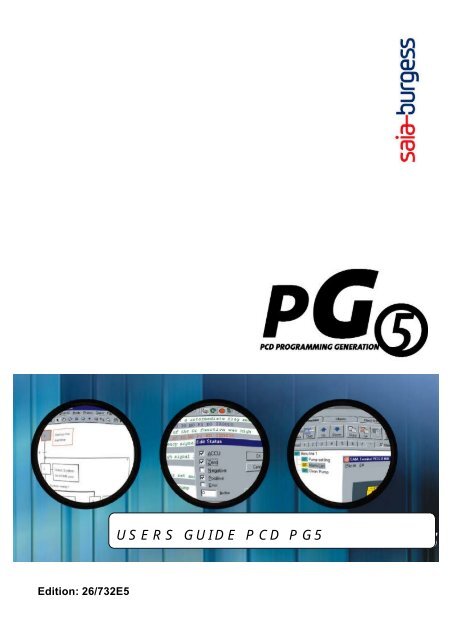
Edition: 26/732E5<br />
USERS GUIDE PCD PG5
Workshop PG5<br />
Welcome<br />
© Saia-Burgess Controls Ltd.
Workshop PG5<br />
Welcome<br />
<strong>Introduction</strong>.<br />
Welcome<br />
Thanks a lot for your interest in our product. Soon from now you’ll discover<br />
how to write programs for the SAIA PCD as did many developers before<br />
you. In fact there are 250000 PCD’s running today!<br />
Programming a PCD is not hard at all. Although knowledge of PCD programming<br />
is of some help it isn’t required for this Workshop. You’ll learn how<br />
to solve simple problems step by step. Each chapter has some exercises at it’s<br />
end so you can check yourself the progress you have made. We believe that<br />
learning without practice is worthless. Therefore we strongly recommend to get<br />
a PCD with a digital input card and a digital output card before you start. Further<br />
you’ll need a cable PCD8.K111 for the examples.<br />
We wish you good fun. PCD Support Team<br />
What is PG5 all about?<br />
Much like the programming languages C++, Prolog, Assembler were built for<br />
special applications in science and industry, there are different kind of languages<br />
which are widely used in the automation industry.<br />
The languages are very similar from label to label, though the name for one and<br />
the same language may change. The languages are:<br />
• IL Instructionlist<br />
• Graftec<br />
• Fupla<br />
• Kopla also called Ladder<br />
We will see soon exactly how they work. PG5 now is a tool which allows us<br />
create programs for a wide range off applications. But PG5 not only is an editor<br />
for these different languages it will also help us to solve other problems we<br />
may encounter during a project. Tasks like:<br />
• Creating a documentation<br />
• Debugging the program once it runs on the PCD<br />
• Debugging the PCD<br />
• Set-up the configuration of the PCD<br />
• Write the program on an EPROM.<br />
During this course we will go through all these topics and do so by using a step<br />
by step approach. If you feel unsure about some points, then refer to the online<br />
help included in the PG5. You will see that you wont need much more then a<br />
little time and some cups of coffee to get familiar with the programming of<br />
PCD's.<br />
© Saia-Burgess Controls Ltd.
Workshop PG5<br />
Welcome<br />
Icons used in this book<br />
Each chapter contains pictures to help you make sense of the material you are<br />
reading. An other important graphical elements are the icons which highlight<br />
specific information so you can find the most important stuff at a glance.<br />
Warning or special<br />
help Never ignore this<br />
icon. Even if you skip<br />
the other icons, you<br />
don't want to miss this<br />
one.<br />
Technical stuff. If<br />
you are ready for<br />
some additional information,<br />
then read<br />
these points.<br />
Remarks. General<br />
information's about a<br />
topic.<br />
© Saia-Burgess Controls Ltd.
Workshop PG5<br />
Welcome<br />
System requirements<br />
Your PC:<br />
• SVGA or higher resolution monitor<br />
• Pentium 150MHz processor or better<br />
• 32MB of RAM or better<br />
• 30 MB free hard-disk space<br />
• Additional 5 MB free hard-disk space for HMI Editor<br />
• CD-ROM drive<br />
• Microsoft Mouse or compatible pointing device<br />
• TCP/IP Protocol installed for Online connections<br />
• TAPI 2.0 for modem connection<br />
• Microsoft Data Access Components (MDAC) 2.5 for HMI Editor<br />
and/or for Symbol Import/Export from/to Excel.<br />
MDAC 2.5 is automatically installed by the HMI Editor Setup or can<br />
be installed by running d:\pg5\mdac_typ.exe (assuming that d: is your<br />
CD-ROM drive)<br />
For Windows 98 Users: DCOM98 needs to be installed before installing<br />
MDAC 2.5. Run d:\pg5\dcom98.exe to install (assuming that<br />
d: is your CD-ROM drive)<br />
Supported operating<br />
systems:<br />
• Windows 95 B or higher<br />
• Windows 98 Second Edition<br />
• Windows NT 4.0 SP5 or higher<br />
• Windows 2000 Professional<br />
• Windows Me<br />
© Saia-Burgess Controls Ltd.
Workshop PG5<br />
Welcome<br />
Your PCD:<br />
You can write programs for any of the existing PCD’s:<br />
PCD1<br />
PCD2<br />
PCD4<br />
PCD6<br />
Have a look into the hardware manuals for further information about any of the<br />
PCD’s. Programs written with the PG5 will run on any of the PCD’s.<br />
All the examples are written for a PCD2 or PCD1 with:<br />
• 1 digital input card (E110 or E111 type) in slot 1 (equals address 0..7)<br />
• 1 digital output card (A400 type) in slot 2 (equals address 16..23)<br />
• 1 analogue input card (W100 type) in slot 3 (equals address 32..39)<br />
Further you’ll need a cable PCD8.K111 in order to download the program<br />
into the PCD.<br />
Further<br />
Documentation:<br />
For information about existing hardware refer to:<br />
Documentation CD-Rom: Ordernumber 26/801<br />
© Saia-Burgess Controls Ltd.
Workshop PG5<br />
Welcome<br />
1. Getting Started<br />
PROJECT MANAGER 1 - 1<br />
OPEN A NEW PROJECT: 1 - 3<br />
CONNECT YOUR PC TO THE PCD 1 - 6<br />
CONFIGURE THE HARDWARE (TABLE MEMORY CHIPSIZE): 1 - 8<br />
SUMMARY : 1 - 12<br />
ADDITIONAL NOTES: 1 - 13<br />
Exercise<br />
2. Write your first program<br />
MANAGE YOUR PROGRAM FILES. 2 - 1<br />
WRITE YOUR FIRST PROGRAM 2 - 5<br />
BUILD YOUR PROGRAM 2 - 6<br />
LOAD THE PROGRAM 2 - 7<br />
TEST YOUR PROGRAM 2 - 8<br />
SUMMARY 2 - 9<br />
ADDITIONAL NOTES: 2 - 11<br />
3. PCD Resources<br />
HARDWARE RESOURCES 3 - 1<br />
INTERNAL (SOFTWARE) RESOURCES 3 - 4<br />
SYMBOL EDITOR 3 - 13<br />
WORKING WITH SYMBOLS: 3 - 17<br />
ADD SEVERAL SYMBOLS AT ONCE 3 - 18<br />
IMPORT SYMBOLS FROM "EQU" STATEMENTS (PG3): 3 - 19<br />
ADD SYMBOLS DIRECTLY FROM THE PROGRAMEDITOR (ENTER): 3 - 20<br />
REPLACE A FIX ADDRESS BY IT'S SYMBOL (SHIFT + SPACEBAR): 3 - 20<br />
AUTO COMPLETE SYMBOLS (CTRL + SPACEBAR): 3 - 22<br />
AUTO ALLOCATION (WORK WITHOUT FIX ADDRESSES): 3 - 22<br />
FILTER THE SYMBOL VIEW: 3 - 25<br />
RESERVED NAMES: 3 - 26<br />
RESOURCE TABLE: 3 - 27<br />
Exercise<br />
4. FUPLA programming<br />
CREATE A NEW PROJECT AND A NEW FUPLA FILE 4 - 1<br />
THE FUPLA EDITOR 4 - 2<br />
EDIT YOUR FUPLA PROGRAM: 4 - 3<br />
EDIT PAGES 4 - 5<br />
BASIC INSTRUCTIONS: 4 - 7<br />
WRITE YOUR FIRST FUPLA PROGRAM 4 - 10<br />
BUILD AND DEBUG YOUR PROGRAM 4 - 13<br />
DEBUG YOUR PROGRAM ONLINE 4 - 14<br />
SOME RULES: 4 - 17<br />
© Saia-Burgess Controls Ltd.
Workshop PG5<br />
Welcome<br />
Exercise<br />
5. Program Structure<br />
CYCLIC ORGANIZATION BLOCK (COB 0 TO 15) 5 - 1<br />
PROGRAM BLOCKS (PB 0 TO 299) 5 - 3<br />
FUNCTION BLOCKS ( FB 0 TO 999 ) 5 - 5<br />
STRUCTURE VIEW AND EXECUTION PATH 5 - 6<br />
EXCEPTION BLOCK (XOB) 5 - 7<br />
TABLE OF XOB’S 5 - 8<br />
HISTROY TABLE 5 - 9<br />
SEQUENTIAL BLOCKS (SB 0 TO 31) 5 - 10<br />
6. GRAFTEC<br />
SEQUENTIAL BLOCKS (SB 0 ... 31) 6 - 1<br />
OPEN A NEW GRAFTEC FILE 6 - 3<br />
ORGANIZATION OF THE SB’S 6 - 6<br />
GENERAL STRUCTURE OF AN SB 6 - 7<br />
BASIC RULE: ALTERNATE STEPS & TRANSITIONS 6 - 7<br />
TRANSITIONS 6 - 8<br />
STEPS 6 - 9<br />
TYPICAL SEQUENTIAL BLOCK STRUCTURES. 6 - 10<br />
EDIT A SEQUENCE 6 - 11<br />
WRITE YOUR FIRST SEQUENTIAL BLOCK 6 - 15<br />
BUILD AND DEBUG YOUR PROGRAM 6 - 21<br />
HOW TO STRUCTURE GRAFTEC USING PAGES. 6 - 23<br />
7. Instruction List Programming<br />
CREATE A NEW PROJECT AND A NEW INSTRUCTION LIST PROGRAM FILE 7 - 1<br />
THE INSTRUCTION LIST EDITOR "SEDIT" 7 - 3<br />
IL SYNTAX 7 - 5<br />
BASIC INSTRUCTIONS: 7 - 10<br />
WRITE YOUR FIRST IL PROGRAM 7 - 17<br />
BUILD AND DEBUG YOUR PROGRAM 7 - 21<br />
DEBUG YOUR PROGRAM ONLINE 7 - 23<br />
SYNCHRONOUS VIEW 7 - 26<br />
Exercise<br />
8. Additional Tools<br />
DATA TRANSFER UTILITY 8 - 1<br />
CUSTOMIZE MENU 8 - 7<br />
WATCH WINDOW 8 - 9<br />
ONLINE CONFIGURATOR 8 - 13<br />
UPLOAD THE PCD CONTENT AND CREATE A PROJECT 8 - 17<br />
PROGRAM AN EPROM 8 - 22<br />
DOWNLOAD A NEW FIRMWARE VERSION 8 - 23<br />
© Saia-Burgess Controls Ltd.
1. Getting Started<br />
INTRODUCTION: 1<br />
1.1 PROJECT MANAGER 1<br />
1.2 OPEN A NEW PROJECT: 3<br />
1.3 CONNECT YOUR PC TO THE PCD 6<br />
1.4 CONFIGURE THE HARDWARE: 8<br />
1.5 SUMMARY: 12<br />
1.6 ADDITIONAL NOTES: 13<br />
<strong>Introduction</strong>:<br />
Welcome.<br />
In the first Chapter you will learn how to:<br />
♦ Open a new project.<br />
♦ Connect your PC to the PCD.<br />
♦ Configure the PCD.<br />
If you already have some experience with our other programming tools like PG4<br />
or PG3, we suggest that you do not skip this chapter because it will provide some<br />
basic information on how you can manage your projects today.
Workshop PG5<br />
Getting Started - Project management<br />
© Saia-Burgess Controls Ltd.
Workshop PG5<br />
Getting Started - Project management<br />
1.1 PROJECT MANAGER<br />
PROJECT<br />
DEFINITION<br />
In contrast to PG4 or S5, PG5 doesn't handle one PCD, but a whole project<br />
with a multitude of PCD's and Networks.<br />
An entity of several PCD's is called a Project. Project files have the ending<br />
*.5pj<br />
Project<br />
Network<br />
© Saia-Burgess Controls Ltd Page 1-1
Workshop PG5<br />
Getting Started - Project management<br />
© Saia-Burgess Controls Ltd Page 1-2
Workshop PG5<br />
Getting Started - Project management<br />
1.2 OPEN A NEW PROJECT:<br />
Before we start to write our first program we will have to open a new project<br />
with one or several PCD's:<br />
1. Open the PG5 Project manager.<br />
2. Click on File.<br />
3. Click on New Project.<br />
4. Enter a project name.<br />
5. Enter a description about the project.<br />
Enter a project<br />
name.<br />
Enter a description<br />
of<br />
the project.<br />
Click on OK<br />
to confirm<br />
entries.<br />
Don’t activate this<br />
option. We will<br />
manually add a CPU<br />
the first time. If it is<br />
active, just click on<br />
it to deactivate.<br />
© Saia-Burgess Controls Ltd Page 1-3
Workshop PG5<br />
Getting Started - Project management<br />
Now that you have opened a project, your project tree should match the display.<br />
The next step is to add a CPU.<br />
1. Highlight the Project, and right click on it. Then click on New CPU.<br />
2. Or, you can click on CPU in the menu bar, and then click on New.<br />
OR<br />
Enter a<br />
name<br />
Enter a description<br />
about<br />
the CPU.<br />
Click on OK<br />
to confirm<br />
ti<br />
© Saia-Burgess Controls Ltd Page 1-4
Workshop PG5<br />
Getting Started - Project management<br />
Your project tree should match the display below.<br />
Highlight Settings and double click on it. This shows you the three areas where<br />
you can configure your PCD. As you can see, there is Online, Hardware, and<br />
Software.<br />
The first setting is Online. Highlight Online and double click on it.<br />
Or Click on Online from the Tool Bar.<br />
OR<br />
© Saia-Burgess Controls Ltd Page 1-5
Workshop PG5<br />
Getting Started - Project management<br />
Select<br />
PGU<br />
Click on setup<br />
to select protocol<br />
The baudrate and protocol<br />
settings are fixed for<br />
PGU. The port depends<br />
on what is available on<br />
your PC.<br />
Click on OK to<br />
confirm entries<br />
Now the communication protocol is set. Next, we will connect the PCD to<br />
your PC.<br />
1.3 Connect your PC to the PCD<br />
Basic connection:<br />
The standard connection is the direct connection between the PGU port on the<br />
PCD, and the Com1 port on the PC. Use SAIA cable #K111. There is other<br />
configurations available, but this is the one we are going to use with this<br />
workshop. Refer to your hardware manual for the power connection to the<br />
PCD. Now you should be connected to the PC and the PCD should be on.<br />
© Saia-Burgess Controls Ltd Page 1-6
Workshop PG5<br />
Getting Started - Project management<br />
Confirm<br />
connection:<br />
The simplest way to check the connection between the PCD and the PC, is by<br />
clicking on the Online icon. Click on this now.<br />
You will receive this message.<br />
Click<br />
on Yes.<br />
Displays the<br />
connection<br />
tt<br />
Run and Stop are<br />
active when you have<br />
a program downl<br />
Your display should have a HALT<br />
d d<br />
status. Halt is online, but since you have<br />
not downloaded a program, it goes into the halt mode.<br />
If you receive this message:<br />
1. Click on OK.<br />
2. Check that the PCD is on.<br />
3. Check the cable connection between the PCD & PC.<br />
© Saia-Burgess Controls Ltd Page 1-7
Workshop PG5<br />
Getting Started - Project management<br />
1.4 CONFIGURE THE HARDWARE:<br />
Default Hardware<br />
Settings:<br />
There is two areas you can use to enter the hardware settings.<br />
1. Default settings. (will be used if no individual settings are not downloaded)<br />
2. Individual settings. (Custom to the project that is currently active)<br />
To get to the default settings, click on Tools, Options, and then the General<br />
tab.<br />
General<br />
tb<br />
Click on<br />
Default<br />
Hardware<br />
Settings<br />
Enter the<br />
memory.<br />
Enter PCD<br />
type.<br />
Enter the extension<br />
memory, if<br />
Confirm with<br />
OK.<br />
© Saia-Burgess Controls Ltd Page 1-8
Workshop PG5<br />
Getting Started - Project management<br />
Individual<br />
Hardware Settings:<br />
We just covered the entry of the default hardware settings. These would be<br />
useful if you had several PCD’s with the same configuration. You could set the<br />
default settings once, and all the others would be configured via the default<br />
settings.<br />
For projects with one or several different PCD’s, we have the individual hardware<br />
settings.<br />
Highlight Hardware, and double click on it.<br />
Enter the PCD type, the memory and the<br />
extension memory. If you are not sure on<br />
on the memory, you can click on Upload<br />
and the PCD will fill in the memory and the<br />
extension memory for you. This is only available<br />
with the individual settings, it is not<br />
available when setting the default settings.<br />
If you are not sure of the<br />
memory of your PCD,<br />
click on Upload, and it<br />
will enter the data for you.<br />
Click on<br />
Upload<br />
again.<br />
When Upload<br />
is complete<br />
click on<br />
l<br />
© Saia-Burgess Controls Ltd Page 1-9
Workshop PG5<br />
Getting Started - Project management<br />
Download<br />
Settings:<br />
Once you have the settings entered, you need to download the settings. Follow<br />
the steps below:<br />
Once you have the<br />
settings entered,<br />
click on Download<br />
Click on<br />
Download<br />
again.<br />
When the Download<br />
is complete,<br />
click on Close.<br />
The PCD is now configured to your settings.<br />
The software settings file, will be covered in Chapter 3. The next step is to<br />
write your first program. Chapter 2 will take you through this procedure.<br />
© Saia-Burgess Controls Ltd Page 1-10
Workshop PG5<br />
Getting Started - Project management<br />
Important<br />
JUMPERS:<br />
There are several jumpers<br />
on the PCD where you<br />
can choose the kind of memory<br />
chip you are using. (Examples:<br />
EPROM, RAM and some times<br />
Flash).<br />
There is a jumper to indicate if<br />
the memory is > < 1Mbit.<br />
Before the settings are<br />
downloaded, the PG5 reads the<br />
position of these jumpers and<br />
compares it with the setting you<br />
have chosen from the list.<br />
2<br />
1<br />
2<br />
Example PCD2:<br />
If you use an additional memory<br />
chip in the socket 1 and you<br />
encounter problems at this stage,<br />
then check the position of these<br />
jumpers!<br />
2<br />
For further information, please refer to the hardware manual.<br />
© Saia-Burgess Controls Ltd Page 1-11
Workshop PG5<br />
Getting Started - Project management<br />
1.5 SUMMARY:<br />
In this chapter you have learned how to:<br />
♦ Open a new project.<br />
♦ Setup the communication between the PC and the PCD.<br />
♦ Set the default and individual hardware settings.<br />
Additional Notes:<br />
♦ Overview of the Project Manager structure.<br />
♦ Overview of the File Manager structure.<br />
♦ Some information about memory.<br />
© Saia-Burgess Controls Ltd Page 1-12
Workshop PG5<br />
Getting Started - Project management<br />
1.6 ADDITIONAL NOTES:<br />
Project Manager<br />
Structure:<br />
Tool Bar:<br />
All operations are<br />
handled from here.<br />
Message Window: :<br />
Displays Disdd error messages, and the<br />
entire protocol from the assembler.<br />
You can scroll in the protocol<br />
and edit it as you wish.<br />
Data Window:<br />
Displays the content of several<br />
files, such as the Symbol Editor<br />
files, listing files in 3 views:<br />
Data view, Block view, and<br />
Block structure view, and all<br />
map files. Displayed is the<br />
Symbol editor.<br />
File Manager:<br />
Stores all the program and configuration<br />
files for the project. Also can<br />
store files from other programs such<br />
as Word or ElektroCAD. When you<br />
backup the project, all the files are<br />
stored.<br />
© Saia-Burgess Controls Ltd Page 1-13
Workshop PG5<br />
Getting Started - Project management<br />
FILE MANAGER Structure:<br />
Contains all the program files,<br />
which are used by multiple<br />
CPU’s. The modifications in<br />
these files are automatically<br />
reported to all the CPU’s in the<br />
project which reference to the<br />
file in the “Common Files”<br />
folder.<br />
Project Title, and number<br />
of CPU’s in the<br />
Here you can set how<br />
you are going to<br />
communicate with<br />
your PCD. Default is<br />
“PGU direct connec-<br />
Active Project:<br />
There is always one CPU<br />
that is active at any given<br />
time.<br />
All the operations you<br />
execute (build, hardware<br />
settings, download, ect )<br />
corresponds to this project.<br />
A project becomes active<br />
by right clicking on<br />
”<br />
the<br />
CPU and choose “Make<br />
Active”<br />
.<br />
Contains all your<br />
listing and map<br />
files.<br />
Configure your<br />
PCD<br />
hardware and softi<br />
Contains all your<br />
program files.<br />
Files which are<br />
only referenced are<br />
displayed as<br />
shown with<br />
..\filename<br />
© Saia-Burgess Controls Ltd. Page 1-14
Workshop PG5<br />
Getting Started - Project management<br />
MEMORY INFORMATION:<br />
Chips you<br />
can use:<br />
Chips we<br />
support and<br />
supply:<br />
PCD<br />
type<br />
Memory chip<br />
PCD1 Empty socket<br />
1 RAM 256kBit<br />
1 RAM 1Mbit<br />
1 Flash 1Mbit<br />
1 EPROM 512kBit<br />
1 EPROM 1Mbit<br />
PCD2 Empty socket<br />
1 RAM 256kBit<br />
1 RAM 1Mbit<br />
1 RAM 4Mbit<br />
1 Flash 1Mbit<br />
1 Flash 4Mbit<br />
1 EPROM 512kBit<br />
1 EPROM 1Mbit<br />
1 EPROM 4Mbit<br />
PCD4 2 RAM 62256<br />
2 RAM 1MBit<br />
2 EPROM 256kBit<br />
2 EPROM 512kBit<br />
2 EPROM 1Mbit<br />
Order<br />
number<br />
4 502 5414 0<br />
4 502 7013 0<br />
4 502 7141 0<br />
4 502 3958 0<br />
4 502 7126 0<br />
4 502 5414 0<br />
4 502 7013 0<br />
4 502 7175 0<br />
4 502 7141 0<br />
4 502 7224 0<br />
4 502 3958 0<br />
4 502 7126 0<br />
4 502 7223 0<br />
4 502 5414 0<br />
4 502 7013 0<br />
4 502 5327 0<br />
4 502 3958 0<br />
4 502 7126 0<br />
Usable Bytes<br />
in the PCD<br />
17 KB<br />
32 KB<br />
128 KB<br />
112 KB<br />
64 KB<br />
128 KB<br />
32 KB/128KB<br />
32 KB<br />
128 KB<br />
512 KB<br />
112 KB<br />
448 KB<br />
64 KB<br />
128 KB<br />
512 KB<br />
64 KB<br />
256 KB<br />
64 KB<br />
128 KB<br />
256 KB<br />
Extension<br />
memory<br />
(RAM)<br />
None<br />
13 KB<br />
13 KB<br />
13 KB<br />
13 KB<br />
None<br />
24 KB<br />
24 KB<br />
24 KB<br />
24 KB<br />
24 KB<br />
24 KB<br />
24 KB<br />
24 KB<br />
13 KB<br />
None<br />
128 KB if you use<br />
PCD2.M120 Version<br />
J or M150<br />
172 KB if you use<br />
the memory<br />
PCD7.R310<br />
If you order a chip of a certain size, you might receive different types of chips.<br />
Memory chip size Order number Chip type<br />
RAM 256kBit 4 502 5414 0 SRM 2B256SLCX70<br />
HY62256ALP-70<br />
GM76C256CLL-70<br />
M5M5256DP-70LL<br />
TC55257DPL-70L<br />
RAM 1Mbit 4 502 7013 0 LP621024D-70LL<br />
SRM20100LLC70<br />
HY628100ALP-70<br />
GM76C8128CLL-70<br />
M5M51008BP-70L<br />
RAM 4Mbit 4 502 7175 0 HM628512LP-5<br />
KM684000ALP-5L<br />
Flash 1Mbit 4 502 7141 0 AM29F010-70PC<br />
Flash 4Mbit 4 502 7224 0 chip AM29F040 on socket<br />
EPROM 256kBit 4 502 5327 0 UPD27C256AD-10<br />
M27C256B-10F1<br />
TMS27C256-10JL<br />
EPROM 512kBit 4 502 3958 0 AM27C512-15XF1<br />
AMC27C512-15XF1<br />
EPROM 1Mbit 4 502 7126 0 AM27C010-90DC<br />
NM27C010Q-90<br />
M27C1001-10F1<br />
EPROM 4Mbit 4 502 7223 0 AM27C040-100DC<br />
M27C4001-10F1<br />
© Saia-Burgess Controls Ltd. Page 1-15
Workshop PG5<br />
Getting Started - Project management<br />
EXTENSION MEMORY?<br />
Although this point is handled automatically by the configurator, it might<br />
be interesting to know what extension memory is all about:<br />
All the PCD's have sockets where the user can place additional memory.<br />
The user has three options; RAM, EPROM, or FLASH. Some PCD's<br />
have RAM (PCD1 and PCD2 ) already soldered on the PC-Board itself. In<br />
the case of PCD2, the RAM has a content of 32kByte or 128kByte depending<br />
on the hardware version. Depending on your program size, it<br />
may not be necessary to place a memory chip into the empty socket. You<br />
can load your programs into this RAM and work without an additional<br />
RAM or EPROM chip.<br />
If you want your program to be stored on an EPROM, FLASH, or if you<br />
have a large program which is to large for the standard RAM, then you<br />
will have to add an additional memory chip. As soon you place a memory<br />
chip into the empty socket, this memory becomes the main memory and<br />
the small RAM becomes the extension memory. Complicated? A little?<br />
Why bother? Well for one, you now know what this extension memory is<br />
and, if for example, you have your program on an EPROM and you want<br />
to change the content of a DB in the run mode. In such a situation the DB's<br />
in the EPROM can't be changed and the only RAM you'll have will be this<br />
small extension memory. DB stands for Data Blocks, and will be covered<br />
in chapter 3.<br />
© Saia-Burgess Controls Ltd. Page 1-16
EXERCISE<br />
INTRODUCTION: 1<br />
QUESTIONS 1-3: 1<br />
SOLUTION 1: 2<br />
SOLUTION 2&3: 3<br />
<strong>Introduction</strong>:<br />
You have learned to setup a project and how to configure a PCD in the first chapter.<br />
You’ll need to consult the PCD hardware manual for some of the questions.
Workshop PG5<br />
Exercise Chapter1<br />
EX-01-E<br />
© Saia-Burgess Controls Ltd
Workshop PG5<br />
Exercise Chapter1<br />
Questions 1-3:<br />
Memory Configuration<br />
1. You have a PCD 1 with a memory chip like:<br />
JAPAN 9845<br />
HM628512ALP-5<br />
1.1 What does HM628512ALP-5 say?<br />
1.2 What’s the order number of this chip?<br />
1.3 What are jumper settings on your PCD like?<br />
1.4 What are the settings you have to choose in the Hardwareconfigurator?<br />
Firmware<br />
2. Open the PCD and try to find the firmware chip:<br />
3. The label on the firmware chip is:<br />
PCD1. M....<br />
V008<br />
3.1 What does it say?<br />
3.2 Control firmware version on your PCD online.<br />
EX-01-E © Saia-Burgess Controls Ltd. Page 1E-1
Workshop PG5<br />
Exercise Chapter1<br />
Solution 1:<br />
1.1<br />
HM628512ALP-5 for :<br />
HM = Chip provider<br />
62 = RAM<br />
512 = capacity in kByte (Sometimes the capacity is given in kBits)<br />
5 = access time 50 nanoseconds<br />
1.2<br />
The order number is: 4 502 7224 0<br />
(List is in the hardware manual PCD2 and at the beginning of this chapter)<br />
1.3<br />
Memory Configuration<br />
HM62256LP-<br />
R E<br />
WP<br />
As this is a RAM, we have to put the jumper<br />
on R. The E stands for EPROM.<br />
The jumper underneath stands for WP = write<br />
protect. You can’t download your program<br />
anymore it this jumper is set. Set both<br />
jumpers as shown on the picture.<br />
1.4<br />
EX-01-E © Saia-Burgess Controls Ltd. Page 1E-2
Workshop PG5<br />
Exercise Chapter1<br />
Solution 2&3:<br />
Firmware:<br />
2.<br />
Take the hardware manual:<br />
PCD1/2 manual 26/737<br />
PCD 4 manual 26/734<br />
PCD 6 manual 26/735<br />
and you’ll find a drawing in the first<br />
chapter showing the PCD and the FW.<br />
Firmware<br />
RAM<br />
uP<br />
68340<br />
User Memory<br />
24 VDC<br />
RUN<br />
ERR<br />
SPACE A<br />
SUPPLY<br />
3.1 The label says:<br />
PCD1. M....<br />
V008<br />
The firmware is for a PCD1 and will run on any type of PCD1 ( M110,M120<br />
and M130)<br />
Further the firmware is an official one (indicated by the V) and it’s the version<br />
008.<br />
3.2<br />
Connect yourself to the PCD using the K111 cable as shown in the chapter1.<br />
Start the menu: “Online” “ PCDStatus”<br />
And you’ll get the<br />
firmware version:<br />
D1 = PCD1<br />
M1 = M110,<br />
M120<br />
Version 008<br />
EX-01-E © Saia-Burgess Controls Ltd. Page 1E-3
Workshop PG5<br />
Exercise Chapter1<br />
EX-01-E © Saia-Burgess Controls Ltd. Page 1E-4
2. Write your first program<br />
INTRODUCTION: 1<br />
2.1 MANAGE YOUR PROGRAM FILES. 1<br />
2.2 WRITE YOUR FIRST PROGRAM 5<br />
2.3 BUILD YOUR PROGRAM 6<br />
2.5 TEST YOUR PROGRAM 8<br />
2.6 SUMMARY 9<br />
2.7 ADDITIONAL NOTES: 11<br />
<strong>Introduction</strong>:<br />
Now it's time to write our first program. A proper introduction to the FUPLA and<br />
IL programming will follow in the next chapter. It does not matter if you do not<br />
know the difference between FUPLA, KOPLA, IL, etc. (The names change<br />
from company to company ). The main goals of this chapter are:<br />
♦ See how easy a simple program can be done.<br />
♦ Write and download your first program.<br />
♦ Observe the states of your inputs and outputs on the PCD and your PC<br />
monitor.
Workshop PG5<br />
Write your first program<br />
© Saia-Burgess Controls Ltd.
Workshop PG5<br />
Write your first program<br />
2.1 Manage your program files.<br />
There are a lot of different kinds of files in a project. Here, we will cover<br />
program files. There is three editors, and the format you choose to program<br />
in, determines the editor you will use.<br />
S-EDIT is the editor for programs written in IL ( Instruction list or AWL<br />
in German ). IL is a kind of assembler code with 127 different instructions,<br />
which work in combination with very powerful assembler directives.<br />
This will be your tool if you plan to make very fast programs or if<br />
you start to implement your own communication protocols into the PCD.<br />
FUPLA is the editor for all the guys who like to edit their programs in a<br />
graphical environment. ( Like ladder or logic)<br />
The only difference between LADDER and LOGIC is in the way you draw<br />
binary combinations. As soon as you use integer or floating decimal values,<br />
both LADDER and LOGIC become very similar to work with. We<br />
have implemented both LOGIC and LADDER into the same editor.<br />
In addition to the large basic library, a large number of libraries for applications<br />
like HVAC or communications via a modem, ( pager, modem … )<br />
can be purchased.<br />
GRAFTEC is the name of the editor in which you can draw<br />
SEQUENTIAL BLOCS. It is a way to structure and display your program<br />
in a sequential format. This is useful if you want to solve sequential problems<br />
where you have to wait on some internal or external events before<br />
starting the next program step.<br />
© Saia-Burgess Controls Ltd. Page 2-1
Workshop PG5<br />
OPEN A<br />
PROGRAM-<br />
FILE:<br />
Write your first program<br />
In order to start programming you have to know how to open a new program<br />
file:<br />
1. Highlight the folder called " Program Files"<br />
2. Click on the " New File" button or click the right mouse button<br />
OR<br />
3. Fill in the dialog-box as shown below:<br />
Add a name to<br />
your file<br />
Choose to open a new<br />
INSTRUCTION LIST<br />
program<br />
Activate this option<br />
in this example..<br />
Don’t activate<br />
this option in<br />
this example.<br />
We will open<br />
the file later.<br />
© Saia-Burgess Controls Ltd. Page 2-2
Workshop PG5<br />
Write your first program<br />
4. Look at the File Manager and you'll see this program file:<br />
Technical<br />
stuff:<br />
Highlight the file, click<br />
the right mouse button,<br />
then click on Linked to<br />
link or unlink the file<br />
LINKED/<br />
NOT LINKED<br />
An arrow indicates that the file will be linked to the program.<br />
This means the file is part of your project and will be<br />
downloaded to the PCD.<br />
No arrow indicates the file will not be linked to the program.<br />
This can be useful if you have several program files,<br />
which you link for testing purposes, but will not be included in<br />
the final version of your program.<br />
© Saia-Burgess Controls Ltd. Page 2-3
Workshop PG5<br />
Write your first program<br />
© Saia-Burgess Controls Ltd. Page 2-4
Workshop PG5<br />
Write your first program<br />
2.2 Write your first program<br />
Goal:<br />
We will just program one simple equation:<br />
O 32 = I 1+ I 2<br />
(Turn the Output32 on if Input 1 or 2 has an input signal)<br />
Open the<br />
editor:<br />
Highlight and double click the file to open the editor. Enter the six program<br />
lines as shown.<br />
Enter the program<br />
code:<br />
The cursor will start in the<br />
upper left corner. Just type<br />
in COB 0 and enter. The<br />
editor will position the<br />
string for you automatically.<br />
Next don’t move the<br />
cursor, just type in 0 and<br />
enter. Follow this format<br />
for your entries.<br />
© Saia-Burgess Controls Ltd. Page 2-5
Workshop PG5<br />
Write your first program<br />
2.3 BUILD your program<br />
What’s the BUILD<br />
function?<br />
BUILD your program:<br />
The functionality of BUILD is one of the most powerful features of the PG5<br />
package. It provides an automated and optimized procedure to take you from<br />
edit mode into online mode. The PCD system is updated with all the modifications<br />
that have been made to the project files.<br />
.<br />
Compile the program by clicking on the "Build Project" icon.<br />
As soon as you click on the "Build " icon, the program goes through all the<br />
files and assembles one after the other. This process is documented in the message<br />
window, so you'll always know which files are actually assembled. Once<br />
all the files are done, the linking starts. This also is documented in the message<br />
window. If everything is ok, the message window will tell you:<br />
Output to the<br />
MESSAGE<br />
WINDOW:<br />
The program " Inputoutput<br />
combination.src "<br />
has no errors.<br />
All the files that are<br />
linked. (We only<br />
have one file in this<br />
example plus the<br />
basic file called<br />
"~projpg4" which is<br />
always there.)<br />
The build was<br />
successful.<br />
Upon a successful build, your program is ready to be downloaded to the PCD.<br />
© Saia-Burgess Controls Ltd. Page 2-6
Workshop PG5<br />
Write your first program<br />
Download your files<br />
Execute the download by clicking on the "Download" icon.<br />
DOWNLOAD<br />
YOUR<br />
PROGRAM-<br />
FILES:<br />
As soon as you activate Download, the memory settings and the program are<br />
downloaded into the PCD. The current program in the PCD will be erased and<br />
the new program will be downloaded.<br />
As soon as the program is downloaded, the status bar (see picture) will indicate<br />
“Complete. Press close to continue.<br />
© Saia-Burgess Controls Ltd. Page 2-7
Workshop PG5<br />
Write your first program<br />
2.5 Test your program<br />
1. Go online. click on the icon and the start and stop icons will illuminate.<br />
2. Click on the start icon and the PCD is now in the run mode. Confirm<br />
that the run led is on. (The led is located on the front of the PCD).<br />
3. Click on the stop icon and the PCD is now in the stop mode. Confirm<br />
that the run led is off.<br />
4. Click on the start icon to go back into the run mode.<br />
5. Double click on the Input output combination file.<br />
View your program<br />
online:<br />
6. Click on the Asynchronous Data Mode icon. Your program is now<br />
displayed.<br />
7. Activate input 1 and confirm it’s state changes to a high, along with the<br />
state of Output 32. Deactivate Input 1 and activate Input 2. Output 32<br />
should go high again.<br />
8. You have completed your first program!!!<br />
Click on the “Asynchronous<br />
Data Mode” icon.<br />
If you turn on and<br />
off you input 1, the<br />
state will change<br />
on the screen<br />
© Saia-Burgess Controls Ltd. Page 2-8
Workshop PG5<br />
Write your first program<br />
2.6 Summary<br />
You have learned how to:<br />
• Open a new program file.<br />
• Edit a very simple program with one program block. (Program blocks will<br />
be defined later).<br />
• Build your program.<br />
• Download your program.<br />
• Test the program online.<br />
Additional notes in the following pages....<br />
• Build options<br />
• Download options<br />
• Code view mode<br />
© Saia-Burgess Controls Ltd. Page 2-9
Workshop PG5<br />
Write your first program<br />
© Saia-Burgess Controls Ltd. Page 2-10
Workshop PG5<br />
Write your first program<br />
2.7 ADDITIONAL NOTES:<br />
You don't have to know or understand the build options in order to successfully<br />
make a program. However, they are<br />
available if you want to customize the way<br />
your program is built and documented.<br />
Technical<br />
stuff:<br />
To access the options window, activate Tools =><br />
Options.<br />
BUILD<br />
OPTIONS<br />
Each time you build the project you will be asked whether or not you want to<br />
save the project. (We recommend you keep this activated until you become<br />
familiar with PG5)<br />
Stops the build after the first error appears. (If disabled the build will finish the<br />
build process to the end and list all the errors {up to 100}. In any case a<br />
download will be refused).<br />
Downloads the program automatically after a successful build.<br />
Creates a *.MAP file. The MAP file contains statistical information about your<br />
project like lines of code from each program file and the number of text bytes.<br />
Creates a *.lst (list file) during the build process. ( Useful to debug tricky instruction<br />
list programs)<br />
© Saia-Burgess Controls Ltd. Page 2-11
Workshop PG5<br />
Write your first program<br />
Technical<br />
stuff:<br />
You can:<br />
1. Download everything (default)<br />
2. Download only the program blocks that have been changed.<br />
3. Download only the Text or DB segments that have been changed.<br />
DOWNLOAD<br />
The download options can be called from the menu “TOOLS =><br />
OPTIONS” or from the “OPTIONS” button in the “Download Program”<br />
window. (the window above)<br />
DOWNLOAD<br />
OPTIONS<br />
© Saia-Burgess Controls Ltd. Page 2-12
3. PCD Resources<br />
INTRODUCTION: 1<br />
3.1 HARDWARE RESOURCES 1<br />
3.2 INTERNAL (SOFTWARE) RESOURCES 4<br />
3. 3 SYMBOL EDITOR 13<br />
3.4 WORKING WITH SYMBOLS: 17<br />
<strong>Introduction</strong>:<br />
It’s now time to give you a more global view over the elements you can make use<br />
of while writing your application.<br />
The first part is a summary over all the elements we know in SAIA PCD such as<br />
input/outputs or flags, their usage and their address range.<br />
The second part shows you how to use these elements inside the symbol editor.
Workshop PG5<br />
PCD Resources<br />
© Saia-Burgess Controls Ltd.
Workshop PG5<br />
Resources<br />
3.1 Hardware resources<br />
Each program is made up of functions, which allow the user to read, write, and<br />
manipulate different kinds of resources. The resources which allow us to interact<br />
with our environment, are called hardware resources.<br />
3.1.1 Digital<br />
inputs and<br />
outputs<br />
I / O<br />
1 bit (0/1) of information<br />
max. number of I/O<br />
PCD1 32 (*64)<br />
PCD2 64/96/128 (*265)<br />
PCD4 512<br />
PCD6 5120<br />
* Only if the PCD is equipped with the input modules E160 or output modules<br />
A460<br />
Inputs and outputs represent signals which are going to, or coming from the<br />
PCD. Inputs show the state of end-switches, pushbuttons, proximity detectors,<br />
sensors, ect. With outputs you can activate valves, lamps, turn on A/C motors,<br />
ect.<br />
You can read and write outputs. Inputs can only be read.<br />
Inputs and outputs are added to the PCD by placing I/0 cards into one of the<br />
designated slots on the PCD. The start address of a slot is defined either by it's<br />
position (PCD1/2 and 4 ) or by switches (PCD 6 ).<br />
The following example turns the output O 64 on if the inputs number I1 and I2<br />
are both high.<br />
Another way to show such functions is by using boolean equations: O 64 =<br />
I 1 * I 2<br />
Instruction list program:<br />
COB 0<br />
0<br />
STH I 1<br />
ANH I 2<br />
OUT O 64<br />
ECOB<br />
FUPLA program:<br />
(FBox: Binary, AND 2 to 10 inputs)<br />
© Saia-Burgess Controls Ltd. Page 3-1
Workshop PG5<br />
Resources<br />
3.1.2 Time<br />
Most of the PCD's have a built in RTC (real time clock ). ( PCD1.M120/130<br />
and all the PCD2/4/6). You can load the date and time into a register with a<br />
special instruction.<br />
The example shows you how to read the time in your program.<br />
Instruction list program:<br />
COB 0<br />
0<br />
RTIME R 1<br />
ECOB<br />
FUPLA program:<br />
(FBox: Time Related, Time )<br />
This program reads the time from the clock and copies the value into register<br />
R1. Look what the value represents:<br />
R 1 = 093510<br />
09 o'clock 35 minutes and 10 seconds<br />
R 2 = 073990210<br />
week 07, day no. 3 ( Wednesday ), the<br />
10th of Feb 99<br />
© Saia-Burgess Controls Ltd. Page 3-2
Workshop PG5<br />
Resources<br />
3.1.3 Interrupt<br />
inputs<br />
Some of our PCD’s have two inputs called INB1 and INB2. Each time you<br />
have a rising edge on one of these inputs, the normal program cycle will be<br />
interrupted and the PCD will execute a special program block called XOB20 or<br />
XOB25 ( XOB20 for INB1 and XOB25 for INB2 ). These interrupt inputs are<br />
on the following PDC's: PCD1.M120/130, PCD2.M120 and PCD6.M3.<br />
These inputs are capable of a frequency up to 1000 times per second.<br />
Instruction list program:<br />
FUPLA program:<br />
COB 0 ; Main program<br />
0<br />
ECOB<br />
XOB 20 ; interrupt INB1<br />
INC R 2 ; increment the register<br />
; R 2<br />
EXOB<br />
( FBox: Integer, Addition )<br />
Normal input cards have special filters on their inputs. These filters protect the<br />
pin from noise with frequencies higher than 50Hz. Therefore you might have a<br />
situation where you can't react on a signal because it is either to short, or<br />
repeated to fast. In this situation, you can use these inputs as an interesting<br />
alternative to expensive special counter cards like the PCD2.H1XX or<br />
PCD4.H1XX. ( these cards count at speeds between 10 and 160 kHz )<br />
© Saia-Burgess Controls Ltd. Page 3-3
Workshop PG5<br />
Resources<br />
3.2 Internal (software) resources<br />
3.2.1 Flags<br />
How to use<br />
Flags in your<br />
program:<br />
1 bit (0/1) of information<br />
F NV ( non volatile )<br />
0 8191<br />
A flag memorizes one bit of information. There is 8192 flags. (0 is a valid<br />
flag). By default, the flags are non volatile. This means that if you turn off the<br />
PCD, and the flag is a 1, when you turn the PCD back on, it will still be a 1.<br />
(Considering that your battery is good). All volatile flags would be reset to a 0,<br />
if the PCD was turned off). If you want a volatile flag or flags, they can be<br />
configured in the software settings. This is explained below.<br />
The following example writes a high (1) into the Flag number 11 as soon as<br />
inputs 1 or 3 is high. Boolean equation: F 11 = I 1 + I 3<br />
Instruction list program:<br />
COB 0<br />
0<br />
STH I 1<br />
ORH I 3<br />
OUT F 11<br />
ECOB<br />
FUPLA program:<br />
(FBox: Binary, OR 2 to10 inputs)<br />
Setup flags:<br />
By default the flags aren’t volatile. If you want them to be volatile, then you<br />
have to specify so in the software settings. (See example)<br />
© Saia-Burgess Controls Ltd. Page 3-4
Workshop PG5<br />
Resources<br />
3.2.2 Registers<br />
32 bit value<br />
Integer : -2 147 483 648 to +2 147 483 647<br />
Floating decimal : -9.22337E+18 to +9.22337E+18<br />
R<br />
NV<br />
0 4095<br />
A register can contain floating decimal or integer values. Registers are extremely<br />
useful for arithmetic operations or operations with analogue values like<br />
measurements and regulation tasks. You can have up to 4096 Registers. They<br />
are non volatile.<br />
In FUPLA, the lines connected to a register have different colors depending on<br />
their content. If they contain a floating decimal value the lines are yellow, if<br />
they contain an integer value, they are green. You can't interact an integer<br />
value, with a floating decimal values. For example you can't add the two together.<br />
One of the values has to be converted into the other’s value, and then<br />
added.<br />
How to use<br />
Registers in<br />
your program:<br />
The following example adds the number 113 to the content of register 12 and<br />
puts the result into register 54:<br />
R 54 = R 12 + 113<br />
Instruction list program:<br />
COB 0<br />
0<br />
ADD R 12<br />
113<br />
R 54<br />
FUPLA program:<br />
(FBox: Integer, ADD)<br />
Setup<br />
Registers:<br />
Dynamic resources allocation is a powerful feature introduced to free you from<br />
having to specify a fixed address for every resource that you need.<br />
Dynamic resources are used by defining a symbol name for a resource without<br />
specifying an address. You won’t need to change these settings until you start<br />
to write large programs with a large number of registers.<br />
You must increase the dynamic space settings in case of assembling errors like<br />
"Auto allocation overflow for type: R".<br />
© Saia-Burgess Controls Ltd. Page 3-5
Workshop PG5<br />
Resources<br />
3.2.3 Constants<br />
32 bit value<br />
Integer: -2 147 483 648 to +2 147 483 647<br />
Floating decimal: -9.22337E+18 to +9.22337E+18<br />
Constants are fixed values that do not change during the program. They are<br />
written into a register.<br />
Example: fix coefficients like PI = 3.1415.<br />
The next example loads the register R 4 with a fixed value of ( 100 ). Then the<br />
register R 4 is divided by 0.25. Because the register R 4 contains an integer<br />
value and we want to divide it by a decimal value ( 0.25 ), you have to convert<br />
R4 into a decimal value. We copy R4 into R3500 (register we are sure is not<br />
being used), convert R3500 into a decimal value, and then divide R3500 by<br />
0.25. The result of the division is placed into R 5. R5 is then copied into R 6,<br />
and R6 is then converted into an integer value.<br />
How to use<br />
constants in<br />
your program:<br />
Instruction list program:<br />
FUPLA program:<br />
COB 0 ;Cyclic organization<br />
0 ; block<br />
LD R 4 ;load 100 into R 4<br />
100<br />
COPY R 4 ;convert the integer value<br />
R 3500 ;from integer to<br />
IFP R 3500 ;floating decimal<br />
0<br />
FDIV R 3500 ;divide the value by 0.25<br />
2.5e-1<br />
R 5 ; and place the result<br />
;into R5<br />
FBoxes: Integer: Move<br />
Converter: Int to float<br />
Floating decimal: Divide<br />
Converter: Float to Int<br />
COPY R 5<br />
R 6<br />
FPI R 6<br />
0<br />
ECOB<br />
;convert the result back to<br />
; integer<br />
© Saia-Burgess Controls Ltd. Page 3-6
Workshop PG5<br />
Resources<br />
3.2.4 Counters<br />
& Timers<br />
31 Bit value ( 0 … 2 147 483 648)<br />
T/C V NV<br />
0 31 1599<br />
Timers and counters can have a value between 0 and 2 147 483 648 (31Bit) and<br />
they share the same address range: 0 to 1599. Usually addresses 0 to 31 is<br />
dedicated to the timers, and addresses 32 to 1599 are dedicated to the counters.<br />
Of course, you can configure this to your own personal settings. The timers by<br />
default, have a time-base of 100ms. (This means that the system will decrease<br />
every timer by one, every 100ms): The time base can be changed in the<br />
“Software Settings”, along with configuring the timer/counter addresses.<br />
Timers are volatile, counters are not.<br />
Timers and Counters can only contain positive values. Their value can be<br />
changed by loading a new value with the LD instruction.<br />
Timer values decrease only. Counters can count up or down, using the instruction<br />
INC/DEC. (Inc Dec ).<br />
Timers and counters can also be used with binary instructions<br />
When a timer or counter contains a non-zero value its state is High (1), when<br />
its content is zero its state is Low (0).<br />
Setup<br />
Timer/Counters:<br />
The distribution of the address range between timers and counters can be altered<br />
in the " Software Settings ". This is also where you can change the timebase<br />
of 100ms<br />
The more timers you declare, the greater the load on the CPU. This is<br />
also true if you lower the timebase. Take this into consideration before<br />
you change the number of timers or lower the timebase.<br />
Example: 100 timers will take about 2% of the CPU’s capacity.<br />
© Saia-Burgess Controls Ltd. Page 3-7
Workshop PG5<br />
Resources<br />
Timer Example:<br />
You have a high signal on Input 4. On the rising edge of this signal you want<br />
to send a high signal out, output 65. This signal will have a duration of 2,5<br />
seconds.<br />
Integer value:<br />
Load the timer:<br />
LD T 1<br />
25<br />
Value displayed by the<br />
output "t" of the<br />
XPluse FBox<br />
Binary value:<br />
Value displayed by the output Q<br />
Instruction list program: FUPLA program:<br />
Solution:<br />
COB 0 ;organization block 0<br />
0 ; time out time<br />
STH I 4 ;If input 4<br />
DYN F 12 ;sees a rising edge<br />
LD T 1 ; load the timer1<br />
25 ; with 2,5 seconds<br />
STH T 1 ;copy timer state<br />
OUT 0 65 ;to the output O65<br />
ECOB<br />
(FBox: Time related, Exlusive Pulse)<br />
Technical stuff:<br />
Time constants<br />
Timers in the SAIA PCD are decremented at a rate defined by the “Software<br />
settings” “Timer” “Timebase”(normally 100ms). The actual time defined by a<br />
constant which is loaded into a Timer changes if the “Timebase” is changed.<br />
This means that if the “Timebase” setting is changed, then all Timer load values<br />
must also be changed. To overcome this problem, the “time” data type can<br />
be used to declare Timer load values. If a time value is used, then the linker<br />
calculates the actual Timer load value according to the “Timebase” settings.<br />
Format:<br />
T#nnnS|MS<br />
Examples: DelayTime EQU T#100MS ;100 milliseconds<br />
OneDay EQU t#86400s ;86400 seconds<br />
© Saia-Burgess Controls Ltd. Page 3-8
Workshop PG5<br />
Resources<br />
Counter Example:<br />
We will program a counter which counts up each time the input 5 receives a<br />
signal. Each time input 6 receives a signal, the counter will count down. (the<br />
counts will be activated on the rising edge of the input signal). The counter can<br />
be set to zero with a high on input 2. We will load the initial count with 3.<br />
This is just an example. If you are a little confused, don’t worry you will understand<br />
it better once we start actually writing some programs.<br />
Load the counter:<br />
LD C 35<br />
3<br />
Integer value:<br />
Increment the counter:<br />
INC C 35<br />
Read the counter content<br />
and display it on the output<br />
LD C 35<br />
0<br />
Binary value:<br />
Q equals high if the counter content<br />
is not zero.<br />
STH C 35<br />
Solution:<br />
Instruction list program: FUPLA program:<br />
COB 0 ;Cyclic organization block<br />
0 ;<br />
STH I 1 ;If input 1 equals 1<br />
LD C 35 ;then load the counter 35<br />
3 ; with 3<br />
STH I 2 ; If input 2 equals 1<br />
LD C 35 ; then load the counter<br />
0 ; with zero<br />
STH I 5 ;If there's a rising edge<br />
DYN F 13 ;on input 5<br />
INC C 35 ;then increment the counter 35<br />
STH I 6 ;If there's a rising edge<br />
DYN F 14 ;on input 6<br />
DEC C 35 ;then decrement the counter<br />
ECOB<br />
( FBox:<br />
Counters, UP-Down pre-set and<br />
clear)<br />
© Saia-Burgess Controls Ltd. Page 3-9
Workshop PG5<br />
Resources<br />
3.2.5 Texts &<br />
Data blocks<br />
TEXT/DB<br />
Main memory<br />
NV<br />
0 3999<br />
Extension memory NV<br />
4000 (PCD4/6) 7999<br />
(PCD2) 5999<br />
(PCD1) 4999<br />
Texts and DataBlocks (DB's ) are non volatile. Texts ( string of characters ) are<br />
used for: Messages on displays, texts you want to send to a pager, initial<br />
strings for modems and so on.<br />
DB's are used for data logging, tables and so on.<br />
Technical stuff:<br />
Where are<br />
Text/DB’s saved?<br />
Register, flags, timers, and counters are handled by the system and stored in a<br />
small RAM apart from the main memory.<br />
DB's and texts on the other hand are stored in the main memory, together with<br />
the user program. If you want to use a FLASH Eprom or a normal EPROM for<br />
your main memory, remember that if you are in run mode, you can read from<br />
this memory but not write to it. Therefore you can't alter the content of your<br />
DB’s ( for example your Data login ). In most cases you won’t bother with<br />
this, but if you know that you are going to read and write from your DB's, then<br />
make sure to use DB's which are stored in the extension memory => address<br />
4000 and up. (This is the extension memory and it is always RAM, which<br />
means you can read and write to it).<br />
See how a Text or DB is declared in a Instruction list program:<br />
Example:<br />
Declaration of<br />
BD’s & Text<br />
TEXT 10 "Bonjour!"<br />
TEXT 11 [7]"Hello"<br />
DB 12 45,46,78,999,0<br />
DB 13 [10]<br />
DB 14 [4] 2,3<br />
;Text number 10 contains the string Bonjour!<br />
;Text number 11 is 7 characters long were from<br />
the last 5 are Hello and the first two are spaces.<br />
;DB number 12 with the 5 integer values:<br />
;45.46,78,999,0<br />
;DB number 13 is 10 values long and they are<br />
zero at start up.<br />
;DB 14 is four values long. The first two are 2 &<br />
3 the second ;two are 0<br />
© Saia-Burgess Controls Ltd. Page 3-10
Workshop PG5<br />
Resources<br />
Example:<br />
Data-logger in<br />
FUPLA<br />
See how you can easily log values from an analogue card into the DB 4010.<br />
Every time the signal "Store" comes up, the analogue value is read and then<br />
written into the DB with the number 4010.<br />
© Saia-Burgess Controls Ltd. Page 3-11
Workshop PG5<br />
Resources<br />
© Saia-Burgess Controls Ltd. Page 3-12
Workshop PG5<br />
Resources<br />
3. 3 SYMBOL EDITOR<br />
Before we start programming we have to make a list of all the elements we are<br />
planning to use (number of inputs and outputs, number of timers and so on).<br />
All these elements have to be known by PG5. This is very helpful to find<br />
elements inside the program files, tell us we have committed a programming<br />
error, or help during the debugging process. Therefore we list all the elements<br />
we are going to use in a central tool called “Symbol Editor”.<br />
We use the expression Symbol rather than element because we want to emphasize<br />
that each element has a name (a symbol). Also, giving all your resources<br />
a name makes it easier to read the program.<br />
Elements of a<br />
resource:<br />
Name of the resource:<br />
(can be up to 80<br />
characters long)<br />
Type of the symbol:<br />
Here you specify what<br />
kind of resource you<br />
are using. For example<br />
Input or Register….<br />
Comment:<br />
ADD a long comment<br />
to every resource.<br />
It makes the<br />
program easier to<br />
read.<br />
Filename where<br />
your symbols belong<br />
too. The symbols<br />
are not known<br />
to files other then<br />
this one.<br />
Address/Value:<br />
You have to tell the PG which input or<br />
output you want to assign to this Symbol.<br />
In the case of internal resources (everything<br />
but inputs and outputs) you don’t<br />
have to specify an address. The system<br />
will choose one for you. This is called<br />
auto allocation.<br />
© Saia-Burgess Controls Ltd. Page 3-13
Workshop PG5<br />
Resources<br />
Group your Symbols:<br />
You can group your symbols if you would like to. It makes the program easier<br />
to read. Just use the right mouse button to add a new group to your symbol<br />
editor and then drag ‘n’ drop the symbols you want into this folder:<br />
EXAMPLE: The Group named “Wastepump” contains several symbols:<br />
Within the program file the group name<br />
will be added in front of the symbol<br />
name. The group name and the symbol<br />
name are separated by a dot (see picture):<br />
© Saia-Burgess Controls Ltd. Page 3-14
Workshop PG5<br />
Resources<br />
Scope of symbols:<br />
Symbols are normally known to one file only (their scope is local). As soon as<br />
you open a program file in an editor, the symbol editor with the appropriate<br />
symbol list is opened too:<br />
Example:<br />
Opening the program file named “Pump Management.src”, automatically<br />
opens the “Pump Management” Symbol Editor.<br />
LOCAL, CPU Global<br />
& Symbols from a<br />
Network Editor:<br />
Local Symbols are only know to the one file they belong to.<br />
© Saia-Burgess Controls Ltd. Page 3-15
Workshop PG5<br />
Resources<br />
Global symbols:<br />
CPU 1<br />
GLOBAL SYMBOLS<br />
Global symbols are know to all the files in the CPU.<br />
Make locak symbols<br />
global:<br />
If you want to use the same symbols in several files, then you have to move the<br />
symbols from the local list to the “GLOBAL” list (just mark some symbols in<br />
the list use the “Make Global” function (right mouse click)). Once a symbol is<br />
listed as “GLOBAL”, you can access it from any file within your project.<br />
Sharing data between two different PCD’s is more complicated than sharing<br />
information between files. You need some kind of network connection between<br />
the two PCD’s. This network connection can be designed in our network editor<br />
(to date we support: Sbus, Profibus DP, Profibus FMS and LON Networks).<br />
The “Network Editor” lists all the symbols in the “Network” list, and you can<br />
use them in your program in order to move data from one PCD to the other.<br />
© Saia-Burgess Controls Ltd. Page 3-16
Workshop PG5<br />
Resources<br />
3.4 Working with symbols:<br />
Writing a Symbol<br />
list:<br />
Open the file you are going to work with. This will also open the Symbol<br />
Editor. Click on Group/Symbol, and then press the “INSERT” button. A new<br />
symbol field is added to the list instantly. Enter the symbol name, type,<br />
address/value, and a comment. Press Enter to confirm your entry, and then for<br />
the next symbol, simply press the insert button. Note: The editor automatically<br />
enters the previous symbol name and address but increments them by 1.<br />
(See the picture below). You can change the comment and accept the name,<br />
type, and address/value, or you can overwrite the entry with a new name,<br />
type, address/value, and comment.<br />
If you already have a list started, and would simply like to add a symbol, just<br />
click on the last symbol, press the “INSERT” button and this will open another<br />
symbol field.<br />
© Saia-Burgess Controls Ltd. Page 3-17
Workshop PG5<br />
Resources<br />
Add several symbols<br />
to the Symbol<br />
editor:<br />
You can add a range of symbols to your list if you want. Just enter the symbol<br />
name with the first and the last element number as shown, (Drainpumps1..8 O<br />
32 ;Pumps in building F). 8 is the number of symbols, O is for output, and 32<br />
is the starting address of the range you are entering. Press the “Enter” button,<br />
and the symbol editor will complete the list.<br />
Another option is to enter a symbol<br />
and address in the symbol editor,<br />
open the options window, (click on<br />
Symbols, then Options) enter the<br />
symbol and select “ Create reference<br />
for symbol”.<br />
Click OK, and then highlight the<br />
symbol in the editor. Press the<br />
Insert button, the symbol is entered<br />
but incremented by one. This can be<br />
helpful if you have a string of inputs<br />
or outputs and you want or need to<br />
change the physical address location,<br />
in the software, you would just<br />
change the first one, and all the<br />
others would follow.<br />
© Saia-Burgess Controls Ltd. Page 3-18
Workshop PG5<br />
Resources<br />
Import the Symbols<br />
from the<br />
“EQUATE” statements:<br />
If you have old PG4/3 “Instruction List” files with “equ” statements, then simply<br />
mark the statements and import the elements by clicking on the right mouse<br />
button and choose the option:<br />
The symbols are then moved from the program file into the symbol list.<br />
Import the Symbols<br />
from an other<br />
application:<br />
Or you can import your symbols from another program (Electro CAD) and use<br />
these symbols inside your project. This makes your documentation consistent<br />
over the entire project, and your electrical drawings will have the same labels<br />
in electrical drawing as well as in the program code. Simply use the export<br />
function in your CAD to export the symbols into a text file and import them<br />
into the symbol editor again.<br />
© Saia-Burgess Controls Ltd. Page 3-19
Workshop PG5<br />
Resources<br />
Add a symbol<br />
while typing your<br />
program in Instruction<br />
list:<br />
You can simply write your program and each time you use a new symbol, add<br />
type address and comment to the program (The option in „Tools“ => „Options“<br />
must be activated). Once you press “ENTER” the symbol will be moved into<br />
the list.Example:<br />
ENTER<br />
An other nice thing you can do in Instruction List is replacing an element with<br />
a fix address by the symbol from the table:<br />
SHIFT+SPACEBAR<br />
© Saia-Burgess Controls Ltd. Page 3-20
Workshop PG5<br />
Resources<br />
Add a symbol<br />
while typing your<br />
program in<br />
FUPLA:<br />
The FUPLA Editor works exactly the same. You can enter new symbols to the<br />
Symbol List directly from the FUPLA input/output field.<br />
SYNTAX:<br />
<br />
Write the Symbolname, the<br />
type, a comment and press<br />
“ENTER”<br />
And evidently you can also replace fix addresses by the symbol name by using<br />
the “SHIFT + SPACEBAR” key shortcut.<br />
© Saia-Burgess Controls Ltd. Page 3-21
Workshop PG5<br />
Drag-n-drop symbols:<br />
Resources<br />
You can drag-n-drop symbols from the symbol editor into any editor.<br />
Auto complete<br />
symbols:<br />
If you use long symbol names your program will become easier to read. On the<br />
other hand it will be annoying if you have to re-enter the long symbol name<br />
each time you use it in the program. Therefore you can simply enter the first<br />
letters of a symbol, and then lookup all the symbols which match those letters,<br />
by using the keys “CTRL and SPACEBAR”:<br />
Example:<br />
ENTER<br />
CTRL + SPACE<br />
This works in Instruction list as well as in the FUPLA editor.<br />
Auto allocation:<br />
Until now weve always declared the elements like this:<br />
Symbol name Type Address<br />
Comment<br />
Example: Pumpspeed R 2000 ;Speed in l/min<br />
If you are entering any symbol type, other than an input or an output, you do<br />
not have to enter an address for them. If you don’t enter an address then the<br />
PG5 will give an address to your element at build time. We call this autoallocation.<br />
The PG5 will look up in the software settings the address range<br />
configured for that element, and assign one during the build process.<br />
Example:<br />
You declare a register in your program and you don’t give an address to it:<br />
The register will get a number between 3500 and 4095 during the build process<br />
because in the “Software” settings we declared the dynamic space between<br />
3500 and 4095 for registers.<br />
© Saia-Burgess Controls Ltd. Page 3-22
Workshop PG5<br />
Resources<br />
Enter Texts:<br />
In order to add a text to your PCD you have first to declare a text. You can do<br />
so by entering x after the symbol name. Example:<br />
Double click on the symbol icon to open the text editor:<br />
Don’t forget to use “ “ otherwise your text won’t be valid.<br />
Enter DB’s:<br />
DBs have a special editor too. Read the help for more information<br />
© Saia-Burgess Controls Ltd. Page 3-23
Workshop PG5<br />
Resources<br />
Search for a<br />
symbol:<br />
Often a symbol will be used several times inside the program file or even in<br />
several different files. After a successful build of your program you can “right<br />
mouse button click“ on any symbol and start the “Cross reference” function.<br />
The cross-reference will<br />
list you the<br />
(filename and line number) and how many times a certain symbol was used.<br />
Double-click on any of the listed locations and the program file will open and<br />
the cursor will be on the symbol.<br />
The place where the<br />
symbol was defined.<br />
(Normally<br />
the Symbol editor)<br />
Program filename and<br />
line where the symbol<br />
OILPUMP was used.<br />
Written means<br />
that the symbol<br />
on this line contains<br />
the result of<br />
an operation<br />
The cross-reference tool not only works in SEdit and Fupla but also in the different<br />
views which are available in the project manager.<br />
Example: Block-Structure view<br />
© Saia-Burgess Controls Ltd. Page 3-24
Workshop PG5<br />
Resources<br />
Arrange your<br />
symbols:<br />
Rearrange in the<br />
“List View”:<br />
Symbols are listed in the order you enter them. This way, the symbols you enter<br />
at the same time will stay together even if you add new symbols some time<br />
later.<br />
You can rearrange your symbols by simply changing from “Group view” to<br />
“List view”. Simply click on one of the tabs in order to arrange them by: Name,<br />
Type, Address or Comment<br />
Display with filter:<br />
Once you change back to “Group View” the old order is re-established.<br />
If you have a lot of symbols in your list it’s sometimes convenient to display<br />
only certain types or only symbols with a certain name.<br />
The filter function selects the view. As soon as the filter is active your symbols<br />
will have a different icon.<br />
Example: Symbol editor shows all Elements<br />
Filter is active>Not all the symbols are displayed<br />
© Saia-Burgess Controls Ltd. Page 3-25
Workshop PG5<br />
Resources<br />
Symbol names:<br />
Symbol names are names which can be assigned to elements in the PCD (inputs,<br />
outputs, flags, registers, COBs etc). Symbol names can be up to 80 characters<br />
long and are not case sensitive unless they contain foreign characters.<br />
MotorOn is the same as MOTORON, but GRÜN is not the same as grün.<br />
Symbols have to start with a letter ( a-z, A-Z) a number won't be accepted.<br />
Within the symbol you can mix numbers, letters and underlines "_" as you<br />
wish. You cannot have a space in a symbol name.<br />
Reserved Words cannot be used as symbol names.<br />
Reserved Words:<br />
The following words are reserved, and cannot be used as symbol names:<br />
♦ Assembler declarators, e.g. PUBL, EXTN, EQU, DEF, LEQU, LDEF,<br />
MACRO, ENDM, EXITM etc.<br />
♦ Medium control codes and data types (I, O, F, R, C, T, K, M, COB, FB,<br />
TEXT, X, SEMA, DB).<br />
♦ MOV instruction special codes (N, Q, B, W, L, D).<br />
♦ Condition codes (H, L, P, N, Z, E).<br />
♦ All instruction mnemonics.<br />
♦ Pre-defined symbols.<br />
♦ Internal symbols used for automatic resource allocation, which begin with<br />
underscores, e.g.<br />
______TEXT, _________F.<br />
Internal __CSTART__ symbol, used for $$ assignments.<br />
© Saia-Burgess Controls Ltd. Page 3-26
Workshop PG5<br />
Resources<br />
Summary:<br />
In the PCD we have the following elements to work with :<br />
Element:<br />
Shortform:<br />
Amount:<br />
Specialities:<br />
Inputs I Depends on PCD.<br />
Max = 8191<br />
Outputs O Depends on PCD.<br />
Max = 8191<br />
Registers R 4095<br />
Share the same addresses<br />
Flags F 8191 You can set a range of<br />
volatile flags if you like<br />
to.<br />
Constants K 16383(32Bit) or<br />
8191 (13Bit(##)<br />
Timers T 0 to X<br />
Counters C X to 1599<br />
Texts X 0 to Y<br />
DataBlocs DB Y to 3999<br />
RAM Texts RAM X 3990 to Z<br />
RAM Data RAM DB Z to 4999<br />
Blocs<br />
Share the same addresses.<br />
First timers<br />
then Counters<br />
Share the same addresses.<br />
First texts then<br />
DB’s<br />
Share the same Address<br />
range.<br />
PCD 2 goes up to 5999<br />
PCD 4/6 go up to 7999<br />
Every element ( input / output / register / timer/ ect) in your project can have a<br />
name, these names are called SYMBOLS. There are:<br />
• Symbols from a Network editor<br />
These symbols are known to all the PCD’s in the Workspace. They are created<br />
in one of the network editors like “S-Net”.<br />
• GLOBAL Symbols<br />
These Symbols can be used in every file of the current project. Each project<br />
has it’s own project-shared symbols.<br />
• LOCAL Symbols<br />
These symbols can only be used inside the active program file. Each program<br />
file has it’s own local symbols.<br />
You can search for symbols. You can drag and drop symbols from one editor to<br />
the other. And you can import/export symbols.<br />
© Saia-Burgess Controls Ltd. Page 3-27
Workshop PG5<br />
Resources<br />
© Saia-Burgess Controls Ltd. Page 3-28
EXERCISE<br />
INTRODUCTION: 1<br />
GENERAL QUESTIONS “RESOURCES” 1<br />
<strong>Introduction</strong>:<br />
You have learned a lot about resources now. We will start using them right away<br />
in the next chapters. Therefor we will limit ourselves to three questions of more<br />
general nature.
Workshop PG5<br />
Exercise Chapter3<br />
© Saia-Burgess Controls Ltd.
Workshop PG5<br />
Exercise Chapter3<br />
General questions “Resources”<br />
Question1:<br />
What’s the difference between a counter and a timer once you load them with a<br />
value?<br />
Question2:<br />
What happens if you decrement a counter which contains the value 0 ?<br />
Question3:<br />
What went wrong when you build your program and you’ll get the error message:<br />
Fatal Error 368: Auto-allocation overflow for type: R<br />
Solution2:<br />
Timers are decreased by the system every X milliseconds. (Time can be set in<br />
the Softwaresettings).<br />
Counters are decreased/increased in the user program using the DEC / INC<br />
instruction.<br />
Solution:<br />
Nothing. Timer/Counters only contain positive values. Therefore the counter<br />
value will stay unchanged at 0.<br />
Solution:<br />
The dynamic range for registers in the “Software” settings is too small.<br />
There are too little<br />
addresses in the dynamic<br />
space. Put the<br />
first address to 3000.<br />
In such a situation the<br />
field called “Free”<br />
will be at 0.<br />
© Saia-Burgess Controls Ltd. Page 3E-1
Workshop PG5<br />
Exercise Chapter3<br />
© Saia-Burgess Controls Ltd. Page 3E-2
4. FUPLA programming<br />
INTRODUCTION: 1<br />
4.0 CREATE A NEW PROJECT AND A NEW FUPLA FILE 1<br />
4.1 THE FUPLA EDITOR 2<br />
4.2 EDIT YOUR FUPLA PROGRAM: 3<br />
4.3 EDIT PAGES 5<br />
4.4 BASIC INSTRUCTIONS: 7<br />
4.5 WRITE YOUR FIRST FUPLA PROGRAM 11<br />
4.6 BUILD AND DEBUG YOUR PROGRAM 14<br />
4.7 DEBUG YOUR PROGRAM ONLINE 15<br />
4.8 SOME RULES: 19<br />
<strong>Introduction</strong>:<br />
The most straight forward way to introduce someone to the world of PLC programming is to start<br />
with Fupla programming. Fupla (FUnction PLAn) is a graphical environment which enables you<br />
to draw your programs rather then write them.<br />
Every instruction is represented by an icon which we call an FBox (Function BOX). The programming<br />
itself is simply done by drawing the connection between these different FBoxes. We<br />
do have several hundred of these boxes available. These boxes are organized by libraries. The<br />
basic library is installed standard with the PG5. Other libraries can be added later:<br />
The other libraries you can buy are:<br />
HVAC library: A set of over 200 FBoxes for heating applications.<br />
MODEM library: Enables you to use one or several modems with your PLC. This enables<br />
you to build a network of PLC’s, exchanging data over the telephone line. You can<br />
send SMS or pager messages, and you can even use a remote control with your PLC<br />
using the dial tone of your telephone.<br />
FBoxes for special I/O modules. A lot of our I/O cards such as motor control cards<br />
(Hxx) are delivered with a set of Fboxes. With the help of these FBoxes you can set up<br />
your hardware within minutes.<br />
© Saia-Burgess Controls Ltd. Page 4-1
© Saia-Burgess Controls Ltd. Page 4-2
Workshop PG5<br />
FUPLA programming<br />
4.0 Create a new project and a new FUPLA file<br />
Choose to open a<br />
new project:<br />
Open a new program<br />
file:<br />
To open a new program file in this project, click on the " New File" button or use<br />
the right mouse button.<br />
OR<br />
© Saia-Burgess Controls Ltd. Page 4-1
Workshop PG5<br />
FUPLA programming<br />
Open the editor:<br />
Double-click the new file and the “FUPLA” editor will open.<br />
4.1 The FUPLA editor<br />
Note: FUPLA files have the extension “filename.FUP”<br />
The editor:<br />
Let’s have a quick look at the editor. The program is executed from the top to the<br />
end and from left to right. The input symbols are on the left and the results are written<br />
to the right. Each FUPLA file can have several program blocks and up to 200<br />
pages total.<br />
Program page:<br />
You can draw your programs<br />
inside this field. The program is<br />
organized by pages. The<br />
FUPLA file can have up to 200<br />
pages.<br />
Input fields:<br />
All the input values<br />
are listed on the left.<br />
Output fields:<br />
All the results are<br />
transferred to the<br />
symbols on the right.<br />
The block type (COB, PB,<br />
XOB, ST or TR) and number<br />
are shown on the top.<br />
The page name and number<br />
are shown also.<br />
Symbol Editor :<br />
The input and output<br />
fields interact with the<br />
symbol editor.<br />
© Saia-Burgess Controls Ltd. Page 4-2
Workshop PG5<br />
FUPLA programming<br />
4.2 Edit your Fupla program:<br />
Toolbar:<br />
File handling and<br />
FBox editing tools<br />
Drawing tools<br />
Build your program<br />
and change to project<br />
manager<br />
Block, Page and Symbol<br />
organisation windows<br />
Go Online,<br />
Run, Stop,<br />
Step-by-<br />
Step<br />
Go from page to page.<br />
Insert page. Grid. Zoom<br />
Page<br />
Edit a contact:<br />
1. Click on the "LADDER" icon<br />
2. Choose your function.<br />
3. Place your contact on the drawing area and<br />
click the left mouse button in order to release it.<br />
4. For more information double-click on the<br />
specific function.<br />
1.<br />
2.<br />
4.<br />
© Saia-Burgess Controls Ltd. Page 4-3
Workshop PG5<br />
FUPLA programming<br />
Edit a FUPLA<br />
function:<br />
1. Start the Fbox mode by clicking on the "FBox" icon.<br />
2. Choose a family and then a function within<br />
the family.<br />
3. Place the Fbox on the drawing area by<br />
clicking the left mouse button.<br />
2. Family<br />
1.<br />
4. For further information right-click the Fbox<br />
or the FBox Name on the selection window<br />
Function<br />
4.<br />
Connect the<br />
functions<br />
(first solution)<br />
Connect the<br />
functions<br />
(second solution)<br />
Erase a line or<br />
a function.<br />
1. Click on the “Select” icon.<br />
2. Move your pointer on the Fbox and push the left<br />
mouse button. ( keep the button pressed )<br />
3. Now you may move the Fbox to the desired location.<br />
4. Once two connection points touch each other they<br />
are connected.<br />
1. Click on the “Lines” icon.<br />
2. Place the pointer on the departure point of your<br />
connection and click the left mouse button.<br />
3. Click the left mouse button each time you want to<br />
change direction.<br />
4. Once you arrive to the other connection point just<br />
press the left mouse button a last time and the two<br />
points are connected.<br />
5. If you want to stop editing the line then just press the right<br />
mouse button.<br />
Click on the "Eraser" icon, and click on the part you<br />
would like to delete.<br />
3.<br />
2. 3.<br />
1.<br />
2.<br />
4.<br />
1.<br />
4.<br />
© Saia-Burgess Controls Ltd. Page 4-4
Workshop PG5<br />
FUPLA programming<br />
4.3 Edit Pages<br />
The FUPLA editor organises it’s programs in pages. Each file can have up to<br />
200 pages.<br />
Adding a page to<br />
your program:<br />
When you need to add a page to your program click on Page of the tool bar or<br />
place the curser in the middle of the page (in a blank area) and click the right<br />
mouse button. The pull down menu’s are displayed below. There is two options<br />
here, you can insert the page before the current page, or you can insert a<br />
page after the current page. Simply click on the one you want.<br />
You can also use the PageNavigation Window.<br />
Document<br />
your pages:<br />
Document the pages as you<br />
complete them. It only takes a moment, and can really be useful when you want to<br />
move between different areas of the program file. You will activate the pull down<br />
menu’s as you did to add a page, then highlight and click on Page Properties.<br />
Give the page a name and a comment that lets you know what part of the program is<br />
on the page. Under description you can go into a little more detail about the operation<br />
of the page.<br />
© Saia-Burgess Controls Ltd. Page 4-5
Workshop PG5<br />
FUPLA programming<br />
Navigate<br />
from page to<br />
page:<br />
There is a couple of ways to move from page to page in a program file.<br />
The last three icons on the far right of the tool bar are for this process.<br />
The 2 arrows will scroll you through the pages one at a time. The arrow pointing to<br />
the left goes to a previous page, and the arrow pointing to the right goes to the next<br />
page. When an arrow is white, this is an indication that there is another page in that<br />
direction. If the arrow is gray, than that means there are no pages in that direction.<br />
If you have many pages, then it’s easier to use the Page Navigation Window.<br />
If you have documented your pages, they will be listed in the Page Index. Our display<br />
only shows one page, but if you have several pages, simply highlight the one<br />
you want to bring up and either double click on it, or click on Goto.<br />
© Saia-Burgess Controls Ltd. Page 4-6
Workshop PG5<br />
FUPLA programming<br />
4.4 Basic Instructions:<br />
It would take too long to explain each and every instruction inside the Standard Library<br />
(there are over 200 FBoxes). With time you’ll get to know more and more of<br />
these FBoxes. Read the Technical Information 26/367 E1 for a complete overview.<br />
Still there are two or three Families you have to know right from the start.<br />
The Binary functions:<br />
Word functions:<br />
Analogue values:<br />
You will learn, that there are two different ways to<br />
draw your Programs. (Using FBoxes from the binary<br />
family “FUPLA” or using Contacts “Ladder”)<br />
You’ll learn to know the most important families for<br />
basic register handling and basic arithmetic.<br />
Read and write analogue values from and to your<br />
Wxxx cards.<br />
FBoxes are grouped in different libraries and each library has different families with<br />
FBoxes.<br />
FBOX Selection:<br />
The family selection lists five to twenty<br />
FBoxes in logical order.<br />
PG5 is delivered with a standard library containing<br />
over 200 FBoxes. You can add other<br />
libraries such as Modem or HVAC<br />
Binary Instructions:<br />
Today every PLC Company has some kind of graphical programming tools. There<br />
are basically two different ways to write your programs in graphical environment:<br />
FUPLA or LADDER<br />
(FUPLA vs.<br />
LADDER):<br />
There are no differences between FUPLA and LADDER (also known as Contact<br />
and Logic). FUPLA and LADDER are just two different ways to represent the<br />
same functionality. Whereas LADDER comes from the time we use to work with<br />
relays and hard wire our functions. FUPLA shows the same thing in a logical approach.<br />
In Anglo-Saxon countries you'll usually find that LADDER is more common.<br />
In the continental countries FUPLA is more common. PG5 has implemented<br />
the two into the same editor.<br />
© Saia-Burgess Controls Ltd. Page 4-7
Workshop PG5<br />
FUPLA programming<br />
FUPLA<br />
LADDE R<br />
In FUPLA you always have all the inputs<br />
of an operation on the left side of the<br />
drawing and the outputs on the right side<br />
of the drawing. Boxes then represent the<br />
function inside the drawing area. These<br />
boxes are called FBoxes (FUNCTION<br />
BOX)<br />
In LADDER you'll find a power rail on<br />
the left side and a ground rail on the right<br />
side. The inputs and outputs are represented<br />
by contacts and coils, which are<br />
situated inside the drawing. The logical<br />
functions then are realized by the way you<br />
connect the contacts.<br />
Although the power rails are not shown in<br />
the editor, the LADDER works like<br />
every other LADDER editor. As soon as<br />
you connect a contact to the left, the<br />
input box is considered as a power rail.<br />
Turn on the output number 32 (O 32) as soon as the inputs number 1 (I 1) and 0 (I 0)<br />
are high.<br />
Input<br />
fields<br />
Program<br />
area<br />
Output<br />
fields<br />
The input field is<br />
considered as a<br />
power rail as<br />
soon as a contact<br />
is connected to it.<br />
If you wish<br />
you can connect<br />
the coil to<br />
the right<br />
These two examples have the same functionality. As soon as it comes to data types<br />
other than binary, you won’t have this distinction anymore. (This is also true for RS<br />
Logic or S7).<br />
Note: Lines and connections which represent binary values are always drawn red.<br />
© Saia-Burgess Controls Ltd. Page 4-8
Workshop PG5<br />
FUPLA programming<br />
Besides binary, the most important families are:<br />
INTEGER:<br />
All the FBoxes you’ll ever need for arithmetic with integer values. Also functions<br />
such as compare values or move register content from one register to the next.<br />
Note: Lines which contain an integer value are green.<br />
FLOATING<br />
DECIMAL:<br />
FBoxes for arithmetic operations such as Sinus Log etc. Note: Lines which contain<br />
decimal values are yellow.<br />
CONVERTER:<br />
COUNTERS:<br />
These FBoxes not only convert Integer values to decimal values and vice versa, but<br />
also convert the content of your register into formats such as BCD, IEEE, decimal<br />
and so on.<br />
Groups all the basic counters as specified in the norm IEC 1131.<br />
TIME RELATED:<br />
Groups all the basic timers as specified in the norm IEC 1131 plus some nice additional<br />
timers time related FBoxes like “Chronometer”; “Cycle Time measurement”<br />
and functions for the build in real time clock.<br />
© Saia-Burgess Controls Ltd. Page 4-9
Workshop PG5<br />
FUPLA programming<br />
© Saia-Burgess Controls Ltd. Page 4-10
Workshop PG5<br />
FUPLA programming<br />
4.5 Write your first FUPLA program<br />
Open the file:<br />
At the beginning of this chapter (4), we made a new file called: "Blink with output".<br />
We will write our first code in this file.<br />
GOAL:<br />
We will turn on a pump (Oilpump signal O 32), if the oil level becomes too high<br />
(OilHigh signal Input I 0) and if the machine is in conditional Run (Cond_Run signal<br />
Input I 2) or normal run (NormalRun signal Input I 1). The pump must not run if<br />
there is a emergency stop (Emergency signal Input I 7).<br />
As long as the pump is running a signal lamp will blink. The lamp is connected to the<br />
output 33 (PumpRun_Signal O 33)<br />
Double-click on the file called: "Blink with output.fup" and the FUPLA editor will<br />
open.<br />
Prepare the symbols:<br />
Before we start to write our program, we have to make a list of the symbols we are<br />
planning to use. Enter the following symbols into the Symbol Editor: (Refer to page<br />
3-13 if you need help on entering symbols)<br />
Now the programming<br />
begins:<br />
The pump runs if the machine is in conditional run OR normal run:<br />
Select the “OR” FBox from the family “Binary” and draw the first combination:<br />
© Saia-Burgess Controls Ltd. Page 4-11
Workshop PG5<br />
FUPLA programming<br />
Now we make the connections to turn on the pump if one of the above signals is<br />
active, AND if the oil level is too high, AND if there is NO emergency signal.<br />
Select the “AND” FBox from the “Binary” family and place the FBox behind the OR<br />
function and click ONCE with the left mouse button:<br />
The “AND” FBox is now placed behind the OR function. Move the mouse pointer<br />
downward and the FBox stretches, giving you the choice of two to ten inputs. If<br />
you click a second time the FBox is drawn to the board. Draw a FBox with three<br />
inputs:<br />
Add the symbols to the drawing and connect the missing links:<br />
Drag-n-Drop these<br />
from your symbol<br />
list.<br />
© Saia-Burgess Controls Ltd. Page 4-12
Workshop PG5<br />
FUPLA programming<br />
Invert binary signals:<br />
In the event of an emergency stop, the motor must not run. To achieve this,<br />
we have to invert the emergency stop signal.<br />
Activate the “Invert” tool and click on the line pin of the AND FBox:<br />
Calling the help on<br />
FBoxes:<br />
The only thing missing, is the blinking lamp.<br />
Add a blinker from the “Blinker” family (For more information on the different blinkers,<br />
right click on the FBox Name in the FBox Selection Window or place the<br />
FBox on the drawing board and double click on the FBox:<br />
Take the FBox “Blink dely T” and add it to the drawing.<br />
The "Time Value" is always given in 100<br />
ms.<br />
Example: If you enter a 10 in the column<br />
“Address/Value", of your symbol list that<br />
means that the Blinker will blink in 1.0 second<br />
intervals. Add this to your symbol<br />
editor list.<br />
An “En” input on a FBox<br />
always stands for Enable.<br />
Example:<br />
The output Q will only blink<br />
if the signal connected to En,<br />
stays high.<br />
© Saia-Burgess Controls Ltd. Page 4-13
Workshop PG5<br />
FUPLA programming<br />
4.6 BUILD and debug your program<br />
BUILD:<br />
Once you have finished the drawing, you can compile the entire program by clicking<br />
on the BUILD button.<br />
You can use the build button from the<br />
program editor or from the<br />
Project Manager. It is on both tool<br />
bars.<br />
Message Window:<br />
The message window will show you all the information you'll need:<br />
If you have entered the<br />
program correctly then the<br />
message window should<br />
now tell you:<br />
Build successful. Total<br />
errors: 0 Total warnings: 0<br />
If there are any errors in the drawing, then it will be displayed in red letters. Click<br />
on the red letters, and it will take you to the error in your program.<br />
© Saia-Burgess Controls Ltd. Page 4-14
Workshop PG5<br />
FUPLA programming<br />
4.7 Debug your program online<br />
Believe it or not but programs tend to have errors. ( this is also true for our competitors<br />
). Therefore we have prepared a number of online functions which come in<br />
handy when you debug your program. Following is an explanation of these functions.<br />
Start/Stop your<br />
PCD:<br />
1. Download your program<br />
2. Go online.<br />
3. Start and stop your PCD.<br />
As you start and stop the PCD,<br />
observe the run led on the front of<br />
the PCD.<br />
View your program<br />
online:<br />
The logical state of binary values is displayed by thick and thin lines. Highlighted<br />
(thick) lines are high and logic zero is displayed by a thin line.<br />
You cannot edit your program while you are online.<br />
© Saia-Burgess Controls Ltd. Page 4-15
Workshop PG5<br />
FUPLA programming<br />
Display values<br />
while your online:<br />
If you have programs with integer or decimal values, you can monitor the content of<br />
the line by inserting a probe.<br />
Just click on a line and the actual value will be displayed.<br />
By double clicking on a probe you can activate the "Probe Display Format" window,<br />
where you can choose the format you would like to have displayed.<br />
Step by step<br />
Tests:<br />
Once your online with a program, you can also set break points in your program.<br />
1. Go online<br />
2. Choose the menu "MODE" and switch from "Set Probe " to " Set Breakpoints"<br />
3. Your pointer changes and you can set breakpoints where you wish. The program<br />
will stop at the break points and will wait for further instructions.<br />
4. Each time you press "F11" or the menu "Online" "step by step", the PCD executes<br />
one single instruction.<br />
© Saia-Burgess Controls Ltd. Page 4-16
Workshop PG5<br />
FUPLA programming<br />
F11<br />
F11<br />
5. F12 will start the PCD and will execute nonstop all the instructions until the<br />
next break point.<br />
6. Clicking on the breakpoint for a second time makes the breakpoint disappear.<br />
© Saia-Burgess Controls Ltd. Page 4-17
Workshop PG5<br />
FUPLA programming<br />
© Saia-Burgess Controls Ltd. Page 4-18
Workshop PG5<br />
FUPLA programming<br />
4.8 Some rules:<br />
1. Each type has it's own color. Binary => Red<br />
Integer => Green<br />
Floating decimal => Yellow<br />
2. You cannot connect different data types together but, you can convert<br />
values from one type to the other.( see FBox Family " Converter" )<br />
3. You cannot draw loops.<br />
4. Your not allowed to define outputs without connecting them to a function.<br />
5. You cannot connect an input field directly to an output field. To do this,<br />
you would use a "MOVE" FBox.<br />
There are "MOVE" FBoxes for binary, integer and decimal values.<br />
( See corresponding family )<br />
© Saia-Burgess Controls Ltd. Page 4-19
Workshop PG5<br />
FUPLA programming<br />
6. Dynamic inputs are marked with a triangle on the inputs:<br />
Dynamic inputs are inputs which only react on a rising edge. If you want<br />
an input to react on the rising edge and the specific input isn't dynamic,<br />
then you can add a "Dynamize" FBox in front of the input<br />
( Family Binary )<br />
In LADDER a dynamic contact looks like this:<br />
( rising edge )<br />
7. The program is read from the top left corner of the 1 st page, to the bottom right<br />
corner of the last page. You can never jump inside a FUPLA program. If you wish<br />
to execute program parts conditionally then you have to structure your program in<br />
blocks. (Read the chapter Program structures)<br />
If you want to know which FBox is executed in which order then click the menu<br />
"Page" "FBox Priorities”<br />
8. A couple of notes on the symbols in the left and right columns of the program page<br />
(input and output fields). As space is limited, the details of the symbol cannot be<br />
displayed all the time. You can view the details by placing the cursor on the symbol<br />
field for one second.<br />
Also, if you change the symbol name in the drawing (input or output field) then the<br />
symbol in the symbol editor won’t be affected. If you change the symbol name,<br />
type, address, or comment in the symbol editor, then this will change the name,<br />
type, address, or comment of all the input/output fields which hold this symbol<br />
name.<br />
© Saia-Burgess Controls Ltd. Page 4-20
EXERCISE<br />
INTRODUCTION: 1<br />
FUPLA PROGRAMING EXAMPLES: 1<br />
TIMERS AND COMPARE FUNCTIONS 13<br />
COUNTERS AND BLINKER : 17<br />
<strong>Introduction</strong>:<br />
The time has come to start with the real programming. In each example we'll try to<br />
reach a new goal. Refer to the manual if you run into problems.
Workshop PG5 Exercise Chapter 4<br />
© Saia-Burgess Controls Ltd.
Workshop PG5 Exercise Chapter 4<br />
Fupla Programing Examples:<br />
In chapter 4, you learned how to open a Fupla file, and enter the program content.<br />
The following is some examples to help you get comfortable with drawing a program,<br />
and to introduce you to a few of the F-boxes and their function.<br />
AND Gates:<br />
1. Open the project “Chapter 4” ( this is the project you opened at the begining of<br />
chapter 4).<br />
2. Create a new file and name it AND_GATES. Then open it.<br />
3. Enter the following symbols into the Symbol Editor list:<br />
4. Click on the F-box selector.<br />
Available F-<br />
box families.<br />
Click here to display<br />
all the available<br />
functions of active<br />
the family.<br />
© Saia-Burgess Controls Ltd. Page 4E-1
Workshop PG5 Exercise Chapter 4<br />
Highlight and<br />
click on Binary<br />
Hightlight and<br />
click on “And”<br />
You should now have the “And” symbol on the program page. You can move it to<br />
any location on the page by moving your mouse. When you have it where you want<br />
it, click the left mouse button one time, and this will paste the symbol to this location.<br />
Move the mouse vertically to choose the number of inputs you want. Minimum<br />
is 2 and maximum is 10. Once you have the inputs you want, click on the left mouse<br />
button, and the symbol is set. You can now highlight the symbol, and move it horizontally<br />
but only horizontally. (You have to click and hold the button on)<br />
Place one AND gate with 2 inputs and one AND gate with 4 inputs on the program<br />
page.<br />
© Saia-Burgess Controls Ltd. Page 4E-2
Workshop PG5 Exercise Chapter 4<br />
In the symbol list, highlight each symbol and drag and drop them in the columns on<br />
the sides of the program page. Left side or column is for inputs and the right side is<br />
for outputs.<br />
You should now have a display that matches the one above.<br />
Now we can draw the connections. Click on the Line Mode Icon<br />
This will activate a black dot on the page. You can move this dot to the starting<br />
point of your connection, click the left mouse button one time, this will paste the<br />
beginning point. Move the mouse to the next point where you want to make a connection<br />
or change direction. Click left mouse button. (note: you can only move horizontally<br />
or vertically). Follow this format until you get to the final destination of the<br />
connection. Double click the left mouse button and the connection is complete.<br />
Follow this format until all the connections are complete. Your display should be<br />
similar to the one below.<br />
© Saia-Burgess Controls Ltd. Page 4E-3
Workshop PG5 Exercise Chapter 4<br />
Next:<br />
1. Build and donwload the program. (If you need a little help with<br />
building or downloading, refer back to chapter 2).<br />
2. Go on line.<br />
3. Activate the run mode. (refer to chapter 2 for help)<br />
Observing the led’s on your PCD, activate input 0 and input 1. Led 0 and led one<br />
should be on. Also, Output 0 (led 32) should be on.<br />
Turn input 0 and input 1 off, and activate input 2 and input 3. Led 2 and led 3<br />
should be on, but no output leds should be on.<br />
Leave input 2 and input 3 on, and activate input 0 and input 1. Now input led 0,<br />
led 1, led 2, and led 3, should be on, along with output 0 and output 1. (led 32<br />
and led 33)<br />
Binary Inverter:<br />
Using the same program, we will introduce the binary inverter. The binary inverter,<br />
converts the logic 1 or high, to a logic 0 or low, and vice-versa.<br />
1. Deactive the run mode, and go offline.<br />
2. The binary inverter is located on the toolbar of the Fupla editor. The icon is<br />
.<br />
3. Click on the icon and this symbol will be displayed.<br />
4. Position the tip of the arrow where you would like to insert the inverter.<br />
Click the left mouse button one time and this will paste the invert symbol<br />
to the pin. Position the pointer on the symbol and click the left button to<br />
remove the symbol.<br />
Place an inverter symbol to the AND gate of your program to match the display<br />
above. Build and download the program, go online, and activate the run mode. In<br />
the previous exercise, All the inputs had to be high to activate output 1. (Led 33).<br />
Now, input 1, input 2, and input 3 have to be high, and input 0 has to be low, to<br />
activate output 1. (Led 33)<br />
Spend a little time inserting the inverter symbol, creating different scenarios.<br />
Confirm the operation of the different scenarios by testing your programs. You will<br />
find that this symbol is a very useful and commonly used symbol.<br />
Below are a few examples.<br />
© Saia-Burgess Controls Ltd. Page 4E-4
Workshop PG5 Exercise Chapter 4<br />
Comparaters:<br />
Comparaters are used to compare two values. These values can be two integer<br />
values, or two decimal values. The output is a binary value of a 1 or a 0.<br />
There are several options for comparaters:<br />
1. two values are equal<br />
2. one value is greater than another.<br />
3. one value is greater than or equal to another.<br />
4. one value is smaller than another.<br />
5. one value is smaller or equal to another.<br />
These are your choices.<br />
Create a new file, and name it Comparaters. Open the file, and click on the F-<br />
box selector icon. (If you don’t remember this icon, refer back to the AND gates<br />
segment). Now activate the pull down menu for the F-box family selections.<br />
(again, refer to the AND gates segment for help).<br />
Highlight and click on integers. Next, activate the pull down menu for the funtions.<br />
Highlight and click on “is equal to”. Your display should look like this:<br />
Position and paste four comparaters on the program page. Do this in a vertical<br />
format.<br />
Now the symbols are in place, so we need to create the symbol list.<br />
Enter into the list the following:<br />
Drag and drop the MainControl symbol and all the input symbols into the left column<br />
of your program page. Drag and drop the output symbols into the right column<br />
of your program page.<br />
© Saia-Burgess Controls Ltd. Page 4E-5
Workshop PG5 Exercise Chapter 4<br />
Draw your connections, to match the drawing below.<br />
Position these in the center of<br />
the page. We will be adding<br />
to this program<br />
Build and download the program. (Make sure that the AND_GATE file is unlinked).<br />
Go online and observe the ouput Leds. Led 32 and 35 should be on.<br />
Led 33 and 34 should be off. The comparaters are comparing their value to 0. If<br />
their value is equal to zero, then their output is high.<br />
Counters:<br />
Using this same program, we will add a counter to it.<br />
1. Make sure you are offline.<br />
2. Click on the Eraser icon<br />
Place this on what you want<br />
to delete and click the left<br />
mouse button.<br />
3. Erase all the lines that connect to the left column. (there should be no lines<br />
left of the comparaters).<br />
4. Open the pull down menu for Families, and select “Counters”.<br />
5. Open the pull down menu for function and select “Up wrap around with<br />
clear”<br />
6. Paste the counter where all the lines were, left of the comparaters.<br />
7. Add to the Symbol list, Input4 and Input5. Both will be inputs, with there<br />
address being the same as their input number. Comment for Input4 is “resets<br />
counter to zero” and for Input5, “toggle to activate count”. Change the<br />
Address/Value of Input3 from 0 to 3.<br />
© Saia-Burgess Controls Ltd. Page 4E-6
Workshop PG5 Exercise Chapter 4<br />
8. Remove MainControl from the left column. This can be done by highlighting<br />
the symbol in the left column and pressing delete. It will still be listed in the<br />
symbol list. If you highlight it in the symbol list and delete, it will delete it<br />
completely. (Note: symbols in the symbol list, do not have to be used in the<br />
program).<br />
9. Click on the line mode icon and make the connections as follows:<br />
A. Connect input4 to Clr of the counter.<br />
B. Connect input5 to Up of the counter.<br />
C. Connect input3 to Max of the counter.<br />
D. Connect Cnt of the counter to the top pin of all 4 comparaters.<br />
E. Connect Input0 to the other pin of the first comparater, Input1 to the<br />
open pin of the second comparater ect. Yes, Input3 goes to both Max<br />
of the counter and to the comparater.<br />
Your program should look similar to the drawing below.<br />
Build and download the program. Go online and activate the run mode.<br />
Toggle input 5 on and off, and observe the Leds, 32, 33, 34, and 35.<br />
Every time you toggle input 5 on and off, the counter increments and the comparater<br />
that matches the counter number, activates it’s output. The counter is set up to<br />
count 0, 1, 2, 3, 0, 1, 2, 3, 0, 1, 2, 3, ect,<br />
XOR Gates:<br />
The next function we are going to cover, is the exclusive OR gate. This is in the<br />
binary family. Open the F-box selector, and activate the exclusive OR symbol.<br />
© Saia-Burgess Controls Ltd. Page 4E-7
Workshop PG5 Exercise Chapter 4<br />
The function of the exclusive OR gate is that when one of the inputs are high,<br />
then the output is high. If more than one of the inputs is high, then the output is<br />
low. You can have 2 to 10 inputs, but only one can be high, to activate the output.<br />
Erase the lines that are connected to the right column. Paste 2 exclusive OR<br />
gates between the comparaters and the right column. Each gate should have 2<br />
inputs. Delete Output1 and Output3 from the right column. Connect the outputs<br />
from the 2 top comparaters to the inputs of the top exclusive OR gate. The outputs<br />
from the bottom 2 comparaters should then be connected to the bottom exclusive<br />
OR gate. The output of the top exclusive OR gate should be connected<br />
to Output0 and the bottom one should be connected to Output2. Something<br />
similar to the drawing below.<br />
Build and downloadBuidBuild<br />
Build and download the program. Go online and activate the run mode. Toggle<br />
input 5 on and off. When the counter is at 0 or 1, Led 32 will be on. When the<br />
counter is at 2 or 3, the Led 34 will be on.<br />
FLIP-FLOPS:<br />
The last F-box family we are going to cover, is the Flip-Flop.<br />
Open the file AND_GATES, make sure to link this file, and unlink the Comparaters<br />
file.<br />
Open the F-box selector, and choose the Flip-Flop family and the function of the<br />
Type RS dynamized.<br />
© Saia-Burgess Controls Ltd. Page 4E-8
Workshop PG5 Exercise Chapter 4<br />
The function of the RS dynamized Flip-Flop is that of a latch. When there is a<br />
signal going from low to high on the R input, the latch is said to be reset, and the<br />
output Q will be low, and stay in this state, until a signal going from low to high<br />
on the S input occurs, and then the latch is said to be set, and the output Q will<br />
be high. If both receive a low to high signal at the same time, the output will be<br />
low.<br />
Erase all the connections to both the right and left column. You will have just two<br />
AND gates on the page. Change the AND gate that has 4 inputs from 4 to 2.<br />
(you will have to erase it and put a new one on the page) Remove any binary<br />
inverter symbols from the inputs of the AND gates. Paste the RS Flip-Flop between<br />
the AND gates and the right column. Connect Input0 and Input1 to the<br />
top AND gate and Input2 and Input3 to the bottom AND gate. Connect the<br />
output of the top AND gate to the R input of the Flip-Flop and the output of the<br />
bottom AND gate to the S input of the Flip-Flop. Connect the Q output of the<br />
Flip-Flop to the Output0 of the right column. Delete Output1 from the right column.<br />
Your program should look similar to the drawing below.<br />
Build and download the program. Go online and activate the run mode.<br />
When Input0 and Input1 go high, this will reset the flip-flop and Q will be low.<br />
Turn on Input2 and Input3, and Q will be high. Led 32 should be on. Turn Input0<br />
and Input1 on again, and Q will go low. Set and reset the Flip-Flop several times<br />
to see the operation. Remember this is a dynamized Flip-Flop, so it operates on<br />
the rising edge of the signals. There are a few different versions of this Flip-Flop<br />
available.<br />
FINAL<br />
PROJECT:<br />
The purpose of this project is to give you some practice writing/drawing a program.<br />
Create a new file and give it a title. Open the file and fill in the symbol editor list to<br />
match the list below.<br />
© Saia-Burgess Controls Ltd. Page 4E-9
Workshop PG5 Exercise Chapter 4<br />
Here is a list of the F-boxes we are going to be using:<br />
Integer………… “is equal to” comparater<br />
Binary………… “AND” gate<br />
Binary………… “XOR” gate<br />
Flip-Flop……… “Type RS dynamized”<br />
Blinker………… “Blink Delay T”<br />
Counter………… “Up Down with preset and clear”<br />
This program will be a counter that counts 0 – 50 and when it reaches 50, it will<br />
reset back to 0 and continue to count, each time reaching 50 and resetting. You<br />
can also select to have it count from 50 – 0, and resetting to 50 each time it<br />
reaches 0.<br />
A drawing of the program is on the next page. Draw the program, build and<br />
download it. Go online and activate the run mode. Activate count up or count<br />
down, depending on which direction you wish to count. Activate Count_Run.<br />
The counter is now running. To see the counter working, click on Mode in the<br />
tool bar, and activate “Set Probes” Then take the curser and place it where you<br />
want a probe, and then click the left mouse button. A probe will display the value<br />
of the selected location.<br />
© Saia-Burgess Controls Ltd. Page 4E-10
Workshop PG5 Exercise Chapter 4<br />
© Saia-Burgess Controls Ltd. Page 4E-11
Workshop PG5 Exercise Chapter 4<br />
© Saia-Burgess Controls Ltd. Page 4E-12
Workshop PG5 Exercise Chapter 4<br />
Timers and Compare functions<br />
Working with registers, constants, timers and flags<br />
This time the types are not limited to binary values and you can use all the resources<br />
we saw like Registers, flags and so on.<br />
Open a new FUPLA file in the Project Manager and call it TIMER.<br />
This is what we are going to do:<br />
Example:<br />
Daily-Timer<br />
Create a small program where you can turn on and off a machine every day at the<br />
same time.<br />
Use the following symbols:<br />
HMS = hours, minutes and seconds (current time)<br />
ONTime =Time where you want to turn the machine on<br />
OFFTime=Time where you want to turn the machine off<br />
© Saia-Burgess Controls Ltd. Page 4E-13
Workshop PG5 Exercise Chapter 4<br />
In the Family “Time related” you will find a Fbox called “TIME” this Fbox reads the<br />
time from the PCD. The output shows the time as an integer value off six digits.<br />
HHMMSS. The color off the output is different to the color off the lines we had in<br />
our first example. That is because each and every type has its own color like:<br />
• RED lines are binary value<br />
• GREEN lines are integer and so on.<br />
You can’t connect two lines that have different types and you can’t connect two<br />
outputs either.<br />
Goal:<br />
You learn the difference between different types ( binary, integer,…. )<br />
You learn how to read the time from the internal clock<br />
You learn to how to compare values.<br />
You learn to work with symbols rather then with fix addresses.<br />
You learn how to document your program.<br />
You learn to set the internal clock.<br />
Quite a lot for one example I know.<br />
© Saia-Burgess Controls Ltd. Page 4E-14
Workshop PG5 Exercise Chapter 4<br />
Solution:<br />
1. Open a new FUPLA file ( You don’t need to open a new project ) called<br />
Time.fup<br />
2. Add a comment to your file!!!<br />
3. If there are any other files in your project, then mark them as "notlinked". This way<br />
the file will not be taken into considerations and will not be downloaded to the PCD.<br />
4. Open the FUPLA editor and place the FBox "Time related: Time" and copy the<br />
time to a Register called HMS. You have now the time as an integer value in a register<br />
called HMS<br />
5. Now you have to compare the content of this register with the time where you<br />
want to turn the heating on ONTIME and the time you want to turn the heating off<br />
again OFFTime. ONTime and OFFTime are for the moment just constants. Turn the<br />
heating on at 1 o clock PM => (ONTime=10000) and turn it of at noon (OF-<br />
FTime=120000)<br />
There are several ways to solve the problem. I used the FBox ( "Integer: Is greater<br />
or equal to" and Binary: Xor 2-10 inputs )<br />
I first compare the actual time with the ONTime. If the actual time is bigger than then<br />
the ontime, then you know that its later than OnTime and can basically start the<br />
heating. Except if its already too late, and the OFF time has come. This is then tested<br />
in the next FBox (TurnOFF ) ON_OFF Turns the heatin only on, if TurnON command<br />
is there but the TurnOff command has not arrived yet.<br />
DAY_NIGHT then inverses the signal in the case were you turn on the heating in the<br />
evening but you turn off the heating in the morning.<br />
6. You can add nice names on every FBox if you like to. Just move the pointer on<br />
the FBox press the right mouse button and click on "FBox Properties" and add a<br />
name.<br />
OFF<br />
© Saia-Burgess Controls Ltd. Page 4E-15
Workshop PG5 Exercise Chapter 4<br />
7. Build and download your program.<br />
8. In order to test your program, you have to go online and set the clock to different<br />
times.<br />
8.1 Go online.<br />
8.2 start the Online configurator from the project manager<br />
Click on the button called “Clock” and the second window comes up.<br />
On the left you'll see the time of your PC on the right the time of the PCD. You can<br />
edit PCD time<br />
directly in the<br />
fields. Once<br />
you press ok,<br />
the time is<br />
downloaded<br />
into your PCD.<br />
Try it and test<br />
your<br />
program.<br />
© Saia-Burgess Controls Ltd. Page 4E-16
Workshop PG5 Exercise Chapter 4<br />
Counters and blinker :<br />
Example:<br />
Parking lot<br />
Output 17<br />
(red light) is<br />
lit as soon as<br />
the parking<br />
lot is full<br />
(Lot_full)<br />
Input 0<br />
( NewCar )<br />
Input 1<br />
( Car_leaving )<br />
You have a parking lot with 8 parking slots.<br />
You have to sensors : One at the entrance gate which gives a pulse each time a car<br />
enters. Input 0 (NewCar ) a second one tells you when a car is leaving (input 1<br />
Car_leaving ).<br />
A signal ( output 17 Lot_full ) starts blinking as soon as 8 cars are in the parking lot.<br />
Cars can enter the lot even if the lot is already full !!<br />
Set the counter to 0 when you start up.<br />
Goal:<br />
You learn to know the different types of counters we have.<br />
You learn to document the program.<br />
You'll use a blinker.<br />
You learn how to create a reset signal at start up.<br />
© Saia-Burgess Controls Ltd. Page 4E-17
Workshop PG5 Exercise Chapter 4<br />
© Saia-Burgess Controls Ltd. Page 4E-18
Workshop PG5 Exercise Chapter 4<br />
Solution:<br />
1. Open a new FUPLA file ( You don’t need to open a new project ) called<br />
Lot.fup<br />
2. Add a comment to your file!!!<br />
3. If there are any other files in your project, then mark them as "notlinked". This<br />
way the file will not be taken into considerations and will not be downloaded to<br />
the PCD.<br />
4. Open the FUPLA and enter the input signals at the left and the out put signal at<br />
the right.<br />
5. Place a up- down counter on your sheet and make it count up with each pulse<br />
from Input 0 ( NewCar ) and down with each pulse from input 1 ( Car_leaving<br />
).<br />
FBOX:<br />
Counters: up down with preset<br />
Binary : Dynamize<br />
When you start up your PCD, the counter might already contain a value. So we must<br />
reset the counter at start-up.<br />
The small FBox on the side may be found in the family: ( Binary: Dynamize )<br />
If you start up your PCD, then the input of the FBox "Dyn" goes from 0 to 1 ( When<br />
the constant 1 is loaded into the input ) and stays at one from then on. This change<br />
from 0 to 1 makes the output go to 1 at start-up. The signal is connected to the input<br />
"Set" which then loads "0" into the counter. Cool trick he?<br />
© Saia-Burgess Controls Ltd. Page 4E-19
Workshop PG5 Exercise Chapter 4<br />
Double-clcking on a FBox with triangle on the lower left side always opens a parameter<br />
window.<br />
Inside this parameter window you can set the behaviour of the FBox (Example: PID<br />
regulator or Communication ) . In the case of the "Dynamize" FBox we can choose<br />
how exactly we want the FBox to behave. Set the option "Accept power up edge "<br />
to "Always"<br />
6. Read the counter value and compare it with 8.<br />
7. If the counter value is higher then 8, then make the output 17 blink.<br />
FBox: integer :Is greater than<br />
Blinker:Blink delay T<br />
8. Add a long comment to the Fupla page, explaining what your program does.<br />
9. Print your file<br />
© Saia-Burgess Controls Ltd. Page 4E-20
5.Program structures<br />
INTRODUCTION: 1<br />
5.1 CYCLIC ORGANIZATION BLOCK (COB 0 TO 15) 1<br />
5.2 PROGRAM BLOCKS (PB 0 TO 299) 3<br />
5.3 FUNCTION BLOCKS ( FB 0 TO 999 ) 5<br />
5.4 STRUCTURE VIEW AND EXECUTION PATH 6<br />
5.5 EXCEPTION BLOCK (XOB) 7<br />
5.6 SEQUENTIAL BLOCKS (SB 0 TO 31) 10<br />
<strong>Introduction</strong>:<br />
The key to fast programs, lies in the structure of a program. The structure is the<br />
most important part of your entire project, because it makes your program readable<br />
to others, makes it portable, easier to extend and to maintain. Before you start to<br />
write your program you need to have an idea about all the different tasks your installation<br />
will have to solve. PG5 organizes the program parts in different kinds of<br />
blocks, each with it's special function:<br />
There are five different types of blocks:<br />
CB's ( Cyclic Organization Blocks)<br />
FB's ( Function Blocks )<br />
PB's ( Program Blocks )<br />
XOB's ( Exception Blocks )<br />
SB's ( Sequential Blocks ) called Graftec
Workshop PG5<br />
Program structures<br />
© Saia-Burgess Controls AG
Workshop PG5<br />
Program structures<br />
5.1 Cyclic Organization Block (COB 0 to 15)<br />
What’s a COB:<br />
COB's (Cyclic organization blocks) are foreseen for program parts which are<br />
executed nonstop, without ever waiting stopping. (For example in order to wait<br />
for internal or external events to happen). After Startup of the PCD, the program<br />
starts executing the first COB in the program file and then executes one COB after<br />
the other. If needed you may create up to 16 COB’s. All the COB's are called<br />
automatically one after the other in a never ending cycle.<br />
All signals which need to be treated on a regular basis (for example end-switches for<br />
motor movements, external power-cut or emergency-stop signals, human protection<br />
devices ect) have to be inside a COB.<br />
There has to be at least one COB in the PCD!<br />
It is very important to understand, that the notion of the blocks which<br />
are always executed, is the most important aspect of all PLC's. The<br />
lack of waiting loops is not a failure in the concept of PLC programming,<br />
but a very important security feature. It's the only way you can<br />
guarantee your client that important signals are checked on a regular<br />
basis.<br />
If you write your programs with the “FUNCTION BLOCK EDITOR”, a new file in<br />
a COB is automatically opened for you.<br />
You can then change the block type or comment as you wish.<br />
In instruction list programs, the block is defined by instructions which surround the<br />
program code.<br />
© SAIA-Burgess Controls AG Page 5-1
Workshop PG5<br />
Program structures<br />
Example COB:<br />
Here you have an example program ( once in IL and once in FUPLA) which makes<br />
the output 64 blink at a rate of 1,5 seconds. The program is written in the COB 0.<br />
The COB 0 is followed by the COB 15.<br />
Instruction list program:<br />
LADDER or FUNCTION BLOCK program:<br />
COB 0 ;COB 0 starts here<br />
0<br />
STL T 1 ;If timer 1 equals 0<br />
LD T 1 ;then load it with 1.5 s.<br />
15<br />
COM O 64 ;and toggle the output 64<br />
ECOB ;COB 0 ends here<br />
START UP<br />
COB 15 ;Next block<br />
0<br />
NOP<br />
ECOB<br />
(FBox: Blinker, Blink delay T)<br />
COB’s have<br />
different qualities:<br />
1: COB’s have a number. You can choose between 0 and 15.<br />
2: They can have a name.<br />
3: They have a SUPERVISION TIME. This time (in 10th’s of a ms), says<br />
how long the execution of the COB is allowed to take. If the supervision<br />
time elapses before the COB has finished execution (ECOB reached), the<br />
Exception bloc XOB 11 (will be explained right away) is executed. If there<br />
is no XOB11 programmed, the next COB is started. A supervision time of<br />
0 means that the supervision time is not activated.<br />
4: A comment can also be added.<br />
Example: FBD editor<br />
Example: IL-editor (Instruction list)<br />
2.<br />
1.<br />
3.<br />
4.<br />
3.<br />
2.<br />
1.<br />
4.<br />
© SAIA-Burgess Controls AG Page 5-2
Workshop PG5<br />
Program structures<br />
5.2 Program Blocks (PB 0 to 299)<br />
What’s a PB:<br />
You may also work with PB’s (Program Blocks). PB’s offer a good way to organize<br />
your program in a hierarchical manner. PB’s are only activated if they are<br />
called. They may be called from a COB or from another PB.<br />
There are two ways to call a PB: Conditional call or unconditional call. Conditional<br />
calls depend on the result of a logical operation. You can call the same PB several<br />
times in the program. If one PB calls another PB and so on, then you can do so<br />
up to seven levels.<br />
A PB call can<br />
be conditional<br />
or unconditional:<br />
COB 7<br />
Enable input is always<br />
high. Therefore the PB2<br />
will be called in every<br />
cycle => It's an unconditional<br />
call<br />
PB<br />
PB<br />
PB<br />
PB<br />
When the signal "move"<br />
becomes high the PB is<br />
called. This is a conditional<br />
call.<br />
Program blocks can not only be called from COB's, but also from PB’s, FB’s, or<br />
SB’s.<br />
© SAIA-Burgess Controls AG Page 5-3
Workshop PG5<br />
Program structures<br />
Technical<br />
stuff:<br />
Process image<br />
.<br />
Unlike the PLC's from SIEMENS or Rockwell, our PLC does not<br />
work with a so-called process image. If you work with a process image,<br />
then the PLC reads the state of all connected inputs and outputs at the<br />
beginning of the program cycle. Then during the cycle the PLC doesn't<br />
read and write to the inputs and outputs anymore, but to the image. At<br />
the end of the program cycle the PLC then writes all the results at once<br />
from the image to the outputs. Changes at the inputs which appear during<br />
the program cycle are not taken into consideration. If you want to write<br />
directly to an output during the program cycle you can still do so, but<br />
you have to configure the output consequently.<br />
SAIA PLC’s, always read and write directly from and to the inputs &<br />
outputs. This can be used if you want some program parts (and their<br />
Inputs & Outputs) to be treated more often then the rest of the program.<br />
You just have to put this part of the program into a PB and call the PB<br />
several times during the main cycle. Another nice solution would be to<br />
use an "Exception block" (XOB 14 or 15)<br />
© SAIA-Burgess Controls AG Page 5-4
Workshop PG5<br />
Program structures<br />
5.3 Function Blocks ( FB 0 to 999 )<br />
What’s a FB:<br />
FB's ( Function blocks ) are nearly the same as PB's. Similar to PB's, FB's contain<br />
program parts which can be called from other blocks. This call can be conditional or<br />
unconditional.<br />
The unique difference is that FB's give you the possibility to call the block with parameters,<br />
as where with PB’s, you cannot.<br />
FB's with parameters can only be called from an IL program.<br />
The following example shows a FB which makes an output blink.<br />
The FB is called twice. First it makes the output 64 blink at a rate of 1.5 seconds<br />
and the second output 65 at a rate of 3 seconds.<br />
Call a FB:<br />
; Function block program<br />
FB 1 ; Function Block 1<br />
STL =2 ;If timer = L<br />
LDL =2 ; then load the time<br />
=3<br />
COM =1<br />
EFB<br />
; and toggle the output<br />
;The FB ends here<br />
; End function block<br />
; Main program<br />
;-------------------<br />
COB 0 ;Program start<br />
0<br />
;Call function block<br />
CFB 1 ;Call the FB 1<br />
O 64<br />
T 1<br />
15<br />
;Call function block<br />
CFB 1 ; Call the FB 1<br />
O 65<br />
T 2<br />
30<br />
ECOB<br />
;End main program<br />
© SAIA-Burgess Controls AG Page 5-5
Workshop PG5<br />
Program structures<br />
5.4 Structure View and Execution Path<br />
Once you have built your program, you can view the block structure of the program. Click on<br />
the Block structure view icon, located in the tool bar of the project manager. This will display<br />
the structure, and show you which COB is calling which PB, FB, or SB. The display below is<br />
for the FB example on the preceding page. It shows that FB1 is being called by COB 0 twice.<br />
Block structure<br />
view icon.<br />
Block structure<br />
view<br />
To display the execution path, you need to be online and the program running. Stop<br />
the program and place the curser in the center of the page and right click the mouse.<br />
This will display the pull down menu below. Click on Execution path, and it will<br />
display the path. This works with the above program because it consists of only<br />
FB’s. For a program with several segements, you would have to set break points to<br />
ensure you stop within a FB, PB, or SB. Setting break points is explained in<br />
chapter 7.<br />
The display shows that the FB 1 was called from<br />
the COB 0. (25) is the line number that we return<br />
to when the FB is finished. (10) is the line<br />
that we stopped on in the FB.<br />
© SAIA-Burgess Controls AG Page 5-6
Workshop PG5<br />
Program structures<br />
5.5 Exception Block (XOB)<br />
What’s a XOB:<br />
The exception blocks are treated automatically once a special event occurs. These<br />
events are defined by the firmware, and they cannot be modified by the user. It’s<br />
up to the user whether he want’s to program these events or not.<br />
START-UP PCD<br />
XOB 16<br />
The moment an event occurs,<br />
the PLC stops the task it is<br />
working on, and it starts to<br />
treat the XOB which corresponds<br />
to the event.<br />
When a XOB is<br />
called, the current<br />
program is<br />
stopped.<br />
Once the XOB is<br />
finished, the<br />
program continues:<br />
COB 2<br />
XOB 20<br />
Once the PLC has finished the<br />
XOB, it returns to the program<br />
point where the event appeared<br />
COB 5<br />
If an event appears but there is no program in the corresponding XOB, then the<br />
error LED on the PCD is lit and the PLC continues to run.<br />
Example:<br />
Turn on your PCD, take out the battery and the error LED will come up. If there<br />
was a XOB 2 ( see table on the next page ) in your program, then the LED won’t<br />
come up and the XOB 2 is executed instead.<br />
© SAIA-Burgess Controls AG Page 5-7
Workshop PG5<br />
Program structures<br />
All the XOB’s of<br />
the PCD family:<br />
XOB Description Priority Cold Start<br />
0 Power problem in the main rack (PCD6) or<br />
4 *<br />
WatchDog (PCD1/2)<br />
1 Power problem in the extension rack (PCD 6 ) 2<br />
2 Battery low 2<br />
4 Parity error on the I/O bus (PCD6) 1<br />
5 No response on a module I/O (PCD4/6) 1<br />
6 External error 1<br />
7 Over load of the system due to multiple events. 1<br />
8 Instruction not valid 4 *<br />
9 To many active tasks (Graftec) 1<br />
10 To many PB/FB levels 1<br />
11 Watch dog COB 3<br />
12 To many index registers used 1<br />
13 Error Flag 1<br />
14 Interruption cyclic 3<br />
15 Interruption cyclic 3<br />
16 Cold start 4<br />
17 S-Bus telegram 3<br />
18 S-Bus telegram 3<br />
19 S-Bus telegram 3<br />
20 Interrupt input INB1 3<br />
25 Interrupt input INB2 3<br />
30 No connection with RIO 1<br />
Use of XOB’s:<br />
- Helps to find errors in your program configuration<br />
- Errors in the addresses of the modules<br />
- More then seven program levels<br />
- More then 32 active transitions in a Graphtec structure<br />
- Never ending loop<br />
- Error in a mathematical operation<br />
- Errors in the communication<br />
- Maintenance of your PLC:<br />
- Surveillance of the batteries (needs to be changed every 3 to 4 years)<br />
- Surveillance of special events or very fast reactions on external signals:<br />
- Interrupt inputs<br />
- Interruption of the program every once and awhile<br />
- Interruption of the program when a telegram arrives<br />
- Cold start. Initial values<br />
© SAIA-Burgess Controls AG Page 5-8
Workshop PG5<br />
Program structures<br />
History Table:<br />
In the history table you may find all the hardware and software errors which have<br />
occurred.<br />
This table is updated even if the XOB’s are not programmed. You may find<br />
Time and date<br />
Programme line<br />
Error counter<br />
Text<br />
Very last error<br />
You have to consider the following points:<br />
- Every CPU has his own history<br />
- The line (BATT FAIL) only exists on the CPU 0<br />
- IF the error can be assigned to a program line then the line is indicated. If not,<br />
then it is displayed in hexidecimal.<br />
- - The XOB 0 is never listed.<br />
© SAIA-Burgess Controls AG Page 5-9
Workshop PG5<br />
Program structures<br />
5.6 Sequential Blocks (SB 0 to 31)<br />
Sequential blocks are a collection of so called STEPS and TRANSITIONS.<br />
In the step you execute a part of your program and in the transition you wait for a<br />
condition to appear in order to continue with a following step.<br />
Sequential blocks are created in a special editor. We call this editor GRAFTEC and<br />
the files have the extension *.sfc. The Graftec editor is explained in the next chapter.<br />
It is an excellent tool if you have to solve programming tasks, where your installation<br />
deals with a situation in a sequential manner.<br />
SB's can be called from any other block.<br />
© SAIA-Burgess Controls AG Page 5-10
6. GRAFTEC<br />
INTRODUCTION: 1<br />
6.1 SEQUENTIAL BLOCKS (SB 0 ... 31) 1<br />
6.2 CYCLIC BLOCKS (COB 0 ... 15) 2<br />
6.3 OPEN A NEW GRAFTEC FILE 3<br />
6.4 ORGANIZATION OF THE SB’S 7<br />
6.5 GENERAL STRUCTURE OF AN SB 8<br />
6.6 BASIC RULE: ALTERNATE STEPS & TRANSITIONS 8<br />
6.7 TRANSITIONS 9<br />
6.8 STEPS 10<br />
6.9 TYPICAL SEQUENTIAL BLOCK STRUCTURES . 11<br />
6.10 EDIT A SEQUENCE 12<br />
6.11 WRITE YOUR FIRST SEQUENTIAL BLOCK 17<br />
6.12 BUILD AND DEBUG YOUR PROGRAM 23<br />
6.13 HOW TO STRUCTURE GRAFTEC USING PAGES. 25<br />
<strong>Introduction</strong>:<br />
This chapter covers Sequential Blocks. (also referred to as SB’s). SB’s are made up<br />
of 2 basic elements. Transitions and Steps. Programing SB’s is done using the Graftec<br />
editor. In this chapter, you will learn:<br />
♦ What a SB’s is.<br />
♦ How to call a SB’s.<br />
♦ How to organize several SB’s.<br />
♦ Some typical SB’s structures.<br />
♦ How to program SB’s.<br />
♦ How to structure the program into a pages format.
Workshop PG5<br />
Project management<br />
PG5-06-E.doc<br />
© Saia-Burgess Controls Ltd.
Workshop PG5<br />
Project management<br />
6.1 Sequential Blocks (SB 0 ... 31)<br />
SB’s (Sequential Blocks) work different then the program blocks we learned about<br />
previously. SB’s are very efficient if you have an application where you have to do<br />
several things in a defined sequence.<br />
Example Elevator: “close the door” => “wait until the door is closed” => “move the<br />
elevator to the first floor” => “wait until the elevator has reached the first floor” =><br />
“open the door again”<br />
Because we don’t know how long your program will wait on a particular event (<br />
milliseconds, minutes, days?) before it can continue with the next STEP, you can’t<br />
know the cycle time of an SB. Therefore it’s important to analyze your program and<br />
separate sequential problems in your application from parts which absolutely have to<br />
be in a cyclic block.<br />
Example: If you have an emergency switch on your application, then you want to be<br />
sure that this information is updated regularly. Therefore such information would<br />
never be put into a SB but into a COB.<br />
Typical Graftec Chart<br />
SB sequence<br />
starts here.<br />
The SB number.<br />
(each SB is assigned<br />
a number)<br />
SB sequence<br />
ends here.<br />
SB page<br />
number.<br />
PG5-06-E.doc © Saia-Burgess Controls Ltd. Page 6-1
Workshop PG5<br />
Project management<br />
6.2 Cyclic Blocks (COB 0 ... 15)<br />
The fact that your SB is waiting on an event must under no circumstances block the<br />
rest of the program from being executed continuously. To prevent you from programming<br />
such a structure, a SB must be called from a COB. You can’t have a SB<br />
without a COB!<br />
The SB then will be called once a cycle and the state will be tested. If the SB is<br />
waiting on an event, then the program simply returns to the COB and continues to<br />
execute the COB. The next step of the SB will not be executed until the next cycle<br />
in which it is not in a waiting state.<br />
Cycle starts<br />
here<br />
Cyclic<br />
programs:<br />
Cycle time:<br />
Cycle<br />
ends here<br />
Until now our programs have been executed in an endless loop. They always started<br />
at the beginning of a COB and then one COB after the other was executed until the<br />
program reached the last COB. Once the program reaches the end, it automatically<br />
returns to the beginning of the first COB and starts the cycle all over again.<br />
The time it takes to execute all the COB’s from the beginning of the first COB to the<br />
end of the last COB, depends on the number and type of instructions and FBOX’s<br />
you use in your program. This time is called Cycle time.<br />
The cycle time is typically in the millisecond range. If you know the cycle time, then<br />
you know how long it takes for a PCD output to react on the change of the state of<br />
an input.<br />
Cyclic programs are built with program blocks like COB’s, PB’s, FB’s, SB’s or<br />
XOB’s.<br />
PG5-06-E.doc © Saia-Burgess Controls Ltd. Page 6-2
Workshop PG5<br />
Project management<br />
6.3 Open a new GRAFTEC file<br />
Sequential Blocks are drawn in the Graftec editor. As already mentioned, a SB<br />
must always be called from a COB. Therefore we need to open two new files:<br />
• First we need to create a file containing a COB which calls the SB. This can be<br />
a FBD file for a graphical program (chapter 4) or the COB can be programmed<br />
in an Instruction list program (chapter 7)<br />
• Second we have to open a Graftec file.<br />
Open a new<br />
project:<br />
Start with a new project:<br />
PG5-06-E.doc © Saia-Burgess Controls Ltd. Page 6-3
Workshop PG5<br />
Project management<br />
Open a FUPLA<br />
or a new IL file:<br />
Choose to open<br />
either a new Instruction<br />
List file<br />
or a Fupla file.<br />
Call the SB<br />
from a COB:<br />
Depending on the way you intend to write your program (Instruction list or FUPLA)<br />
you call the SB using a Call SB (CSB) instruction or a Call SB FBOX There is no<br />
difference between the two examples. Open the file you just created, and write the<br />
program as shown below.<br />
Instruction list program:<br />
FUPLA program:<br />
COB 1 ;Cyclic Block starts<br />
0<br />
CSB 0 ; calls the SB 0<br />
ECOB<br />
;Cyclic Block ends<br />
(FBOX: User definable, Call SB)<br />
PG5-06-E.doc © Saia-Burgess Controls Ltd. Page 6-4
Workshop PG5<br />
Project management<br />
Open a new<br />
Graftec file:<br />
If you forget to add a COB, then the message window will tell you during<br />
the build process:<br />
PG5-06-E.doc © Saia-Burgess Controls Ltd. Page 6-5
Workshop PG5<br />
Project management<br />
PG5-06-E.doc © Saia-Burgess Controls Ltd. Page 6-6
Workshop PG5<br />
Project management<br />
6.4 Organization of the SB’s<br />
The SB List:<br />
When you create a graftec file, the graftec editor opens a Sequential Block 0 with an<br />
initial step for you. The SB 0 then is automatically entered into the SB list. To access<br />
this list, open the graftec file, and either click on the SB list icon, or click on<br />
File, then click on SB lists. This will display the list of SB’s in the opened file. You<br />
can have several SB’s in one file. (The maximum number of SB’s in a PCD is 32).<br />
Click on Edit and the SB number is displayed. (don’t confuse this number with the<br />
numbers of the individual elements. This number refers to the entire string of elements<br />
in the SB). Also there is a place to enter a name. We recommend that a<br />
name be entered for the SB. This will be helpful when navigating through your SB’s.<br />
If you don’t enter a name, the list will just display the number.<br />
Add SB’s to<br />
the list:<br />
As mentioned, you can have several SB’s in one file. To add additional SB’s to a<br />
file, open the SB list window, (displayed above) and click on Create. The Edit<br />
SB window will be displayed with the next available SB number.<br />
Enter a name for the SB and click on OK. This will add the SB to the list. You can<br />
then select the SB you want by highlighting it and clicking on Load. This will display<br />
the initial step for the selected SB. Now we can structure the sequence elements for<br />
the SB.<br />
PG5-06-E.doc © Saia-Burgess Controls Ltd. Page 6-7
Workshop PG5<br />
Project management<br />
6.5 General structure of an SB<br />
Initial STEP<br />
Transition<br />
STEP<br />
Sequential blocks are built out of different elements which are called:<br />
Initial Step<br />
Step<br />
Transition<br />
SB’s start with an Initial STEP. When you call the SB for the very first time, then the<br />
SB will execute the program code inside the Initial Step.<br />
6.6 Basic rule: Alternate STEPS & Transitions<br />
Sequential blocks have a strict syntax.<br />
A sequential block always starts with an “Initial Step”<br />
Thereafter transitions and steps must alternate all the time.<br />
You must never have two Steps or two Transitions in a row.<br />
Right<br />
Wrong<br />
In contrast to other PLC's, SAIA PCD’s have implemented the SequentialBlockengine<br />
in the firmware which makes the sequential blocks extremely fast.<br />
PG5-06-E.doc © Saia-Burgess Controls Ltd. Page 6-8
Workshop PG5<br />
Project management<br />
6.7 Transitions<br />
In a transition you put program parts which only have to run until a certain<br />
situation occurs.<br />
For example, you could read the characters from a serial port until a special<br />
character arrives, or you heat-up the dryers of a machine until they are<br />
warm enough to start the installation.<br />
The transition is always finished by an ETR command. The transition is repeated<br />
endlessly as long as the ETR is low.<br />
Example: The Flag 2 is toggled with each program cycle until the input 0 is<br />
high.<br />
FUPLA:<br />
IL:<br />
The " “End Transition"<br />
FBox is called here<br />
The STH instruction sets the ACCU to<br />
a high state, once the input I 0 goes<br />
high. The transition is considered finished<br />
as soon as the ACCU is high at<br />
the end of the transition.<br />
• You don't have to insert a program in every transition. A transition without a<br />
program is always true and will be skipped.<br />
• Transitions written in Instruction List: The ACCU is always high at the beginning<br />
of a transition or a step.<br />
• 2000 steps and transitions can be used to build up to 32 Sequential Blocks.<br />
PG5-06-E.doc © Saia-Burgess Controls Ltd. Page 6-9
Workshop PG5<br />
Project management<br />
6.8 Steps<br />
Steps typically contain program parts which prepare the application for the next task.<br />
The task itself then often is inside a transition.<br />
You want to make your motor move from A to B.<br />
Typically you would first set the speed and direction<br />
of the movement. Second you would start the<br />
movement. Both tasks are non repetitive tasks which<br />
can be in a step since the step is only executed once.<br />
Once the movement is on its way, you'll have to<br />
monitor the movement and stop the motor as soon as<br />
it arrives at the destination B. This monitoring ( For<br />
example: read the end-switch ) has to be done over<br />
and over again until the motor arrives. This would<br />
ideally be done in a transition because transitions are<br />
executed cyclically.<br />
• A Step without a program goes directly to the next transition.<br />
• A Step is only treated once! A step is not cyclic!<br />
PG5-06-E.doc © Saia-Burgess Controls Ltd. Page 6-10
Workshop PG5<br />
Project management<br />
6.9 Typical Sequential Block structures.<br />
Simple<br />
sequence<br />
Simple steps and transitions. There cannot be two steps or<br />
two transitions in a row.<br />
Or function<br />
- maximum 32 tasks in a row.<br />
An OR Task always begins with several transitions in parallel.<br />
The transitions are then executed one after the other<br />
(from the right to the left) until one of the transitions are fulfilled.<br />
After that, only this branch is executed and the execution<br />
of the other transitions stop. An OR function always<br />
ends with several transitions ending up in one step. The<br />
maximum number of transitions in a row is 32.. If there are<br />
more then the XOB 9 is called (read chapter 5)<br />
Simultaneous<br />
Tasks (AND)<br />
Jump over a<br />
sequence<br />
Starts several sequences at once and resynchronizes in one<br />
final transition.<br />
- The common start is given by a transition, which<br />
launches several steps.<br />
- Ends with several steps which are connected to the<br />
same transition.<br />
- You can have up to 32 branches. If there are more<br />
then the XOB 9 is called (read chapter 5)<br />
The two transitions are executed until one or the other is<br />
fulfilled. If the transition on the right is fulfilled first, then<br />
the sequence on the left will be bypassed.<br />
Repeat a<br />
sequence<br />
This example is similar to the preceding example except<br />
that one of the transitions will be fulfilled every cycle. It will<br />
repeat the same step 5 times and then move on to the next<br />
step.<br />
C = 5<br />
C = C - 1<br />
( C = 0 ) ( C > 0 )<br />
PG5-06-E.doc © Saia-Burgess Controls Ltd. Page 6-11
Workshop PG5<br />
Project management<br />
6.10 Edit a Sequence<br />
Once you open a new sequential chart file, the initial step is displayed. The execution<br />
of a step always starts from here. In order to add new elements to the drawing<br />
you can either use the toolbar or the keyboard.<br />
Select<br />
mode<br />
IStep mode<br />
Add a<br />
Transition<br />
Add a<br />
page<br />
Zoom<br />
Toolbar:<br />
Mixed<br />
mode<br />
Add a<br />
Step<br />
Connect<br />
two<br />
points<br />
Edit a simple<br />
sequence:<br />
At the beginning of this chapter we created<br />
the file Pulse.sfc. Open this file and go to<br />
the SB list and load the SB “OpenMain-<br />
Gate”. Do the following exercises:<br />
1. Select the " Mixed Mode "<br />
2. Move the pointer under the the initial<br />
step and click the left mouse button.<br />
3. Move the pointer under the new transition<br />
and click the left mouse button<br />
again.<br />
4. Follow this format.<br />
1. 2.<br />
3.<br />
Draw a connection:<br />
Once the sequence is finished the program<br />
is finished also. If you want the program to<br />
restart, then add a loop. You cannot draw<br />
a connection between two steps or between<br />
two transitions. A loop always starts<br />
at a transition and goes to a step.<br />
1. Select the "Select Mode"<br />
2. Mark the transition you start from.<br />
3. Select the "Link Mode"<br />
4. Click on the step that you want to connect<br />
to the transition.<br />
3.<br />
1.<br />
4.<br />
2.<br />
PG5-06-E.doc © Saia-Burgess Controls Ltd. Page 6-12
Workshop PG5<br />
Project management<br />
Draw an alternative<br />
(OR)<br />
task.<br />
1. Select “Transition mode”<br />
2. Click on a transition which is already<br />
followed by a step.<br />
3. An additional transition is drawn with<br />
each click.<br />
Close an alternative<br />
task<br />
In order to resynchronize your simultaneous<br />
task:<br />
1. Select "Select Mode"<br />
2. Mark the transition you want to close<br />
3. Select "Link Mode"<br />
4. Click on the Step you want to connect.<br />
1.<br />
3.<br />
4.<br />
2.<br />
Edit a simultaneous<br />
Task<br />
(AND)<br />
1. Select “STEP mode”<br />
2. Click on a step which is already followed<br />
by a transition.<br />
3. An additional step is drawn with each<br />
click.<br />
Close simultaneous<br />
task<br />
(AND).<br />
In order to close your OR task:<br />
1. Select "Select Mode"<br />
2. Mark the step you want to close<br />
3. Select "Link Mode"<br />
4. Click on the Transition you want to<br />
connect.<br />
1.<br />
3.<br />
4.<br />
2.<br />
PG5-06-E.doc © Saia-Burgess Controls Ltd. Page 6-13
Workshop PG5<br />
Project management<br />
Add a comment<br />
1. Activate "Select Mode"<br />
2. Use the right mouse button to click on<br />
an element. Choose "Edit" "Element…"<br />
3. Insert your comment.<br />
3.<br />
Insert a sequence<br />
1. Select "Transition Mode"<br />
2. Click on a step which is already followed<br />
by a transition. The editor will<br />
insert a new transition and a new step.<br />
Delete a sequence<br />
3. Activate “Select Mode”<br />
4. Click on the first transition of your<br />
sequence.<br />
5. Click on the last step of the sequence<br />
you want to delete while holding the<br />
“Shift” key down.<br />
6. Press the “Del” key.<br />
Click +<br />
“SHIFT”<br />
“DEL<br />
” key<br />
PG5-06-E.doc © Saia-Burgess Controls Ltd. Page 6-14
Workshop PG5<br />
Project management<br />
Copy/paste a<br />
sequence:<br />
1. Activate "Select Mode"<br />
2. Mark start of sequence.<br />
3. Click on the last step of the sequence<br />
while holding the “Shift” key down.<br />
4. Select the menu "Edit" " Copy"<br />
5. Activate "Select Mode"<br />
6. Click on the point where you want to<br />
insert the sequence.<br />
7. Select the menu "Edit" " Paste"<br />
1.<br />
2.<br />
3.<br />
Insert a sequence:<br />
Remark:<br />
Depending on the position of the element<br />
(transition or step) you select to insert, the<br />
sequence might be inserted underneath or<br />
beside the selected element.<br />
7.<br />
4.<br />
Insert sequence<br />
on a<br />
transition.<br />
Insert sequence<br />
on a<br />
step.<br />
PG5-06-E.doc © Saia-Burgess Controls Ltd. Page 6-15
Workshop PG5<br />
Project management<br />
PG5-06-E.doc © Saia-Burgess Controls Ltd. Page 6-16
Workshop PG5<br />
Project management<br />
6.11 Write your first Sequential Block<br />
Open the file:<br />
Open the file pulse.sfc. Go to the SB list and load the SB called “Pulse”<br />
GOAL:<br />
We will make a program which makes a digital output (Three_ pulses O 33) blink<br />
three times each time we have a digital input (Start_3_pulses I 2) going to high.<br />
Diagram:<br />
Input START_3_pulses:<br />
Output Three_pulses:<br />
1s<br />
1s<br />
Time<br />
Draw the basic<br />
structure:<br />
We always start with the Initial step, where we initialize our elements. Once the<br />
initialization is done we can wait for the start signal. Draw the elements as shown<br />
and add the comment to the fields:<br />
PG5-06-E.doc © Saia-Burgess Controls Ltd. Page 6-17
Workshop PG5<br />
Project management<br />
Once we start the sequence, we are going to turn the output “ Three_pulses” on for<br />
1 second. After a second we turn the output off for a second. We do so three times<br />
and then we restart the sequence:<br />
Choose the SEdit<br />
or FUPLA editor<br />
for your program<br />
code:<br />
Our sequence is finished now. We only have to fill in the program code in each step<br />
and transition. We can edit each Step and transition in Instruction list or FUPLA<br />
which ever you prefer. We will program our Initial step using the FUPLA editor.<br />
Double-click on the Initial step and choose the FUPLA editor:<br />
PG5-06-E.doc © Saia-Burgess Controls Ltd. Page 6-18
Workshop PG5<br />
Project management<br />
Prepare the symbols:<br />
First we will establish a list with all the elements we are going to use in the<br />
SymbolEditor. Enter the elements as shown in the picture below.<br />
Edit the program<br />
code:<br />
Next load the counter (named: PulseCounter) with the constant 3 (named: Number_of_pulses).<br />
To do so we take the “Load counter” FBox from the “Graftec family”).<br />
Remember, do not take counters or timers from the other families. They are<br />
designed to run in a cyclic program only.<br />
How to program<br />
a Transition:<br />
A transition is repeated endlessly until the “End of Tansition” is active. In transition<br />
number 0 we will wait inside the transition until the “Start_3_pulses” input goes high.<br />
Open the Transition 0 and add this Fupla program:<br />
PG5-06-E.doc © Saia-Burgess Controls Ltd. Page 6-19
Workshop PG5<br />
Project management<br />
Use Timers in a<br />
SB:<br />
Timers and Counters from the Standard Library<br />
aren’t made for the use in SB’s. They are designed<br />
for use in COB’s which are executed cyclically over<br />
and over again. If you want to use timers or counters<br />
inside a SB, use the ones from the “Graftec” family.<br />
They are especially designed for Sequential Blocks,<br />
because you can load them in one step and question<br />
the state later on in another step or transition.<br />
What we do in our program is:<br />
Turn the output on and load the timer in the step and<br />
then we go on to the transition where we wait and<br />
question the timer until the time elapsed and the timer<br />
has come to zero.<br />
Repeat the step<br />
and transition for<br />
the time were the<br />
pulse is off:<br />
The Step 2 and Transition 2 are the same as step1 and transition 1:<br />
PG5-06-E.doc © Saia-Burgess Controls Ltd. Page 6-20
Workshop PG5<br />
Project management<br />
Decrement a<br />
counter:<br />
The counter is decremented each time the program<br />
passes by. The counter is only decremented if the<br />
binary input is high (read help on FBox)<br />
Remember: An empty input field is always set to<br />
high! (Chapter 4)<br />
The last two Transitions then are a piece of cake:<br />
PG5-06-E.doc © Saia-Burgess Controls Ltd. Page 6-21
Workshop PG5<br />
Project management<br />
PG5-06-E.doc © Saia-Burgess Controls Ltd. Page 6-22
Workshop PG5<br />
Project management<br />
6.12 BUILD and debug your program<br />
BUILD:<br />
Once you have finished the drawing, you can compile the entire program by clicking<br />
on the BUILD button. (Make sure that the COB file and the Pulse.sfc file are the<br />
only linked files before you activate the build process. You may also want to delete<br />
the SB “OpenMainGate”).<br />
The message window will show you all the information you'll need:<br />
Message Window:<br />
If you have entered the<br />
program correctly then the<br />
message window should now<br />
tell you:<br />
Build successful. Total errors:<br />
0 Total warnings: 0<br />
If there are any errors in the drawing, then the FUPLA will indicate the error in red<br />
letters. Double-clicking on the error message will take you to the error.<br />
Now download the program and go online.<br />
Online tools:<br />
The sequential block can be observed online. The red point always tells you which<br />
transition or step is active.<br />
RUN<br />
STOP<br />
STEP BY<br />
STEP<br />
Active<br />
Transition<br />
(red point)<br />
You can stop the<br />
PLC at any given<br />
moment and<br />
continue the<br />
execution in a step<br />
by step mode.<br />
PG5-06-E.doc © Saia-Burgess Controls Ltd. Page 6-23
Workshop PG5<br />
Project management<br />
PG5-06-E.doc © Saia-Burgess Controls Ltd. Page 6-24
Workshop PG5<br />
Project management<br />
6.13 How to structure GRAFTEC using pages.<br />
What are pages?<br />
In PG5 you can structure your big programs by creating a simple overall structure<br />
which then calls subpages.<br />
Symbol of a page.<br />
Create a page by using<br />
the "page-tool"<br />
Input Step off the page.<br />
A page always starts and<br />
ends with a step.<br />
Navigate from<br />
page to subpage<br />
Output step<br />
off the page<br />
It’s possible to<br />
create pages<br />
within other<br />
pages<br />
Roles while using<br />
pages<br />
- A page always starts and ends with a Step.<br />
- A page can have only one “Input Step” and only one “Output Step”<br />
- You can have pages within pages. (As many as you like)<br />
- You can neither move nor delete an “Input/Output Step”<br />
PG5-06-E.doc © Saia-Burgess Controls Ltd. Page 6-25
Workshop PG5<br />
Project management<br />
Create a page<br />
1. Activate "Select Mode"<br />
2. Click on the first step of your sequence.<br />
3. Press the “Shift” key and click on<br />
the last Step of your sequence.<br />
4. Execute “Page” => “Create”.<br />
1.<br />
2.<br />
3.<br />
Go into a page:<br />
1. Activate "Select Mode"<br />
2. Click on the page.<br />
3. Execute “Page” "Calling Page"<br />
or "Subpage"<br />
1.<br />
Undo a page:<br />
1. Activate "Select Mode"<br />
2. Click on the page.<br />
3. Execute " Page" "Expand"<br />
2.<br />
PG5-06-E.doc © Saia-Burgess Controls Ltd. Page 6-26
7. Instruction list programming<br />
(IL)<br />
INTRODUCTION: 1<br />
7.0 CREATE A NEW PROJECT AND A NEW INSTRUCTION LIST PROGRAM FILE 1<br />
7.1 THE INSTRUCTION LIST EDITOR "SEDIT" 3<br />
7.3 IL SYNTAX 5<br />
7.4 BASIC INSTRUCTIONS: 10<br />
7.5 WRITE YOUR FIRST IL PROGRAM 17<br />
7.6 BUILD AND DEBUG YOUR PROGRAM 21<br />
7.7 DEBUG YOUR PROGRAM ONLINE 23<br />
7.8 SYNCHRONOUS VIEW 26<br />
<strong>Introduction</strong>:<br />
The programming of SAIA PCD’s is based on a very powerful instruction set<br />
which is implemented in every PCD.<br />
Note: Unlike other products, the different SAIA PCD’s products all use the same<br />
instructions. Therefore you can port program files without problems from one<br />
PCD type to the other.<br />
The instruction list editor “S-Edit” will not only help you edit your programs, it<br />
also includes a whole range of powerful troubleshooting and online visualisation<br />
functions which will be a topic at the end of the chapter.<br />
You’ll learn the very basics of PG5 programming in this chapter. You’ll also learn<br />
how to debug your program once it runs on your PCD.<br />
Don’t start this chapter before reading chapter 3. “PCD Resources”.
Workshop PG5<br />
Instructionlist<br />
PG5-07-E<br />
© Saia-Burgess Controls Ltd.
Workshop PG5<br />
Instructionlist<br />
7.0 Create a new project and a new Instruction list program file<br />
Choose to open a<br />
new project:<br />
Open a new program<br />
file:<br />
To open a new program file in this project, click on the " New File" button or<br />
use the right mouse button.<br />
OR<br />
PG5-07-E © Saia-Burgess Controls Ltd. Page 7-1
Workshop PG5<br />
Instructionlist<br />
Open the editor:<br />
Double-click the new file and the “Instruction List” editor will open.<br />
Note: Instruction list files have the extension “filename.SRC”<br />
PG5-07-E © Saia-Burgess Controls Ltd. Page 7-2
Workshop PG5<br />
Instructionlist<br />
7.1 The Instruction list editor "SEdit"<br />
The editor:<br />
The editor opens once you double-click a file with the extension *.src. With<br />
SEdit you can edit your source code. The programs are saved in a text format<br />
and can be viewed and edited by any text editor.<br />
File handling and<br />
text editing tools<br />
Search<br />
tools<br />
Bookmark<br />
Online<br />
tools<br />
Auto-format settings:<br />
Unlike a normal text editor, SEdit will analyse your code and format your inputs<br />
in a user friendly structure. We recommend to use this special function.<br />
( see settings in the picture below ).<br />
PG5-07-E © Saia-Burgess Controls Ltd. Page 7-3
Workshop PG5<br />
Instructionlist<br />
General Syntax:<br />
When you write your program you have to respect a certain syntax which is<br />
described below.<br />
In order to edit your program you can enter the code like you would in any<br />
other windows based text-editor. The code arranges itself in four rows once<br />
you press the enter key, The colors can be changed. ( menu: "TOOLS" =><br />
"OPTIONS" => "COLORS" )<br />
PG5-07-E © Saia-Burgess Controls Ltd. Page 7-4
Workshop PG5<br />
Instructionlist<br />
7.3 IL Syntax<br />
Comments:<br />
IL programs are read by two kinds of entities: humans and compilers. The<br />
compiler requires the source code text to conform exactly to its syntax rules.<br />
For example a COB command demands two parameters. One behind the<br />
command COB itself and the second on the line below it. Humans are not so<br />
particular about how instructions are given, but they often need more explanation<br />
about what the function of the instructions are. Such explanation can be<br />
added to the source code. We call them comments and they are displayed in<br />
green. There are two ways to add a comment.<br />
; All the text from the semicolon to the end of the<br />
line is considered as comment and will be green.<br />
$skip $endskip All the text between the two instructions is<br />
skipped by the compiler and therefore is a comment.<br />
Comments can be added to every line.<br />
Structure:<br />
The code itself is structured in several rows. You can jump from row to row by<br />
using the TAB key.<br />
1. ROW: LABELS, General comments and TEXT<br />
2. ROW: Mnemo code. In this row you insert the actual instruction.<br />
3. ROW: The operands for the instruction. Also called media code.<br />
4. ROW: Comments to the specific program line.<br />
PG5-07-E © Saia-Burgess Controls Ltd. Page 7-5
Workshop PG5<br />
Instructionlist<br />
Case sensitivity:<br />
Instructions and operands are not case sensitive.<br />
Symbols are not case sensitive unless they contain foreign characters, MotorOn<br />
is the same as MOTORON, but GRÜN is not the same as grün.<br />
Labels are symbol names given to locations in a program (program lines),<br />
which are used as destinations for jump instructions or to provide debug information.<br />
Characters allowed in labels are the same as those of symbols.<br />
Texts are case sensitive. ( Example: TEXT 20<br />
"UART:4800,8,N,1;MODE;MC2;DIAG:F0,R100;" ).<br />
Writing programs<br />
with symbols:<br />
Please make sure you have read the chapter "3. PCD Resources ".<br />
Why should we use symbols and name our input and outputs after all?<br />
Couldn’t we simply write our programs directly using the element address like<br />
shown?<br />
COB 0<br />
0<br />
ACC H<br />
STH I 0<br />
ANH I 4<br />
OUT O 33<br />
ECOB<br />
In fact you could write your programs like this if you like to. But:<br />
First symbols make your program easier to read.<br />
Second, imagine you have a program, which is 4000 lines long. The output O<br />
64 was used 30 times (for exp OUT 0 64, SET 0 64 etc.). During the start-up<br />
of your machine you break the output. For one reason or the other you don't<br />
have a spare card handy but lucky you, the output number O 67 off this card is<br />
available. You decide to use this one instead.<br />
You have changed the address of your output from O 64 to O 67. And you<br />
have to do so 30 times!!!!<br />
Had you declared O 64 by a symbol, you would only have to change the address<br />
one time in the symbol editor.<br />
That’s one of the reasons why its better to use symbols rather then fixed addresses<br />
in your program.<br />
PG5-07-E © Saia-Burgess Controls Ltd. Page 7-6
Workshop PG5<br />
Instructionlist<br />
Writing programs<br />
with symbols:<br />
Take the symbol Timer1 for example. This timer is declared in the SymbolEditor:<br />
If you want to use the Timer 11 instead of Timer 12 then you can do so in<br />
one single step directly in the Symbol editor.<br />
Note that the Timer2 has no number at all! You don’t have to give an address<br />
to your elements if you don’t want to. The PG5 will auto allocate all<br />
symbols for you.<br />
PG5-07-E © Saia-Burgess Controls Ltd. Page 7-7
Workshop PG5<br />
Instructionlist<br />
Technical stuff<br />
Addressing<br />
symbols &<br />
using arrays:<br />
By the way:<br />
If you work with symbols, you can add constants or other symbols to your<br />
symbol. Like this you can define a basis address and then refer to an element in<br />
perspective to this basis element.<br />
Example:<br />
An output card PCD2.A400 with 8 outputs is placed into the slot with the start<br />
address 80. We then want to set the third output (output 82):<br />
Definition:<br />
We can simply write: SET OutputMotor1+2 in our program.<br />
A more elegant way is to reserve an array of 8 outputs:<br />
In the program we then set the output 82 like this:<br />
SET OutputMotor1[2]<br />
Auto complete<br />
symbols:<br />
If you use long symbol names your program will become easier to read. On the<br />
other hand it will be annoying if you have to re-enter the long symbol name<br />
each time you use it in the program. Therefore you can simply enter the first<br />
letters of a symbol, and then lookup all the symbols which fit the first letters<br />
by using the keys “CTRL and SPACEBAR”:<br />
Example:<br />
CTRL + SPACE<br />
ENTER<br />
PG5-07-E © Saia-Burgess Controls Ltd. Page 7-8
Workshop PG5<br />
Instructionlist<br />
Labels:<br />
You can make conditional and unconditional jumps in your programs. When<br />
you jump in your program, you have to tell the assembler where you want to<br />
jump to. Labels are symbol names given to locations in a program (program<br />
lines), which are used as destinations for jump instructions.<br />
Characters allowed in labels are the same as those of symbols. Labels can appear<br />
anywhere in the source file, but should be within a code block (COB, PB<br />
etc.), and must not be inside a multi-line instruction.<br />
The value assigned to a label is its offset within the code block where it is defined.<br />
All labels are local to the block in which they are defined, and the same<br />
label can be used many times in the same source module, providing it is always<br />
in a different block. Jumps to labels defined in another block are not allowed.<br />
Example:<br />
Range of symbols<br />
and labels:<br />
Symbols are always "local". Which means that the symbol name is only known<br />
to instructions, which are in the same file as the declaration (see chapter 3). If<br />
you have a symbol with the same name in another file, then the data of the two<br />
symbols won’t get mixed up.<br />
Labels are always local to the block. You can't jump from one file to the other<br />
or from one block to the other. Even if the two blocks are in the same file.<br />
All COB’s, XOB’s, PB’s, FB’s, SB’s, IST’s, ST’s, TR’s, TEXT’s, and<br />
DB’s, are globally known<br />
PG5-07-E © Saia-Burgess Controls Ltd. Page 7-9
Workshop PG5<br />
Instructionlist<br />
7.4 Basic Instructions:<br />
Binary Instructions:<br />
Binary instructions work with inputs, outputs, flags, the state of timers/counters,<br />
and the ACCU.<br />
The ACCU is nothing more then an internal System flag, which memorizes the<br />
result of the last instruction. It can be either high or low.<br />
We have three different types of binary instructions:<br />
1. Type 2. Type 3. Type<br />
The first group of instructions<br />
alters the ACCU<br />
state<br />
In the second group of<br />
instructions, the execution<br />
of the instruction<br />
depends on the ACCU<br />
state.<br />
The third group of instructions<br />
depend on the<br />
ACCU state and alters the<br />
ACCU state.<br />
Input<br />
Output<br />
Or Flag<br />
Instructions:<br />
ACC<br />
STH<br />
STL<br />
Input<br />
Output<br />
Or Flag<br />
Instructions:<br />
DYN<br />
OUT<br />
SET<br />
RES<br />
COM<br />
Input<br />
Output<br />
Or Flag<br />
Instructions:<br />
ANH<br />
ANL<br />
ORH<br />
ORL<br />
XOR<br />
LU<br />
ACCU<br />
ACCU<br />
LU Input<br />
Output<br />
Or Flag<br />
LU<br />
ACCU<br />
LU= Logic Unit<br />
Example:<br />
STH I 14<br />
Sets the ACCU to high if<br />
Input 14 is high.<br />
Example:<br />
RES F 10<br />
Sets the flag 10 to 0 if the<br />
ACCU is high.<br />
Example:<br />
ANH I 23<br />
The ACCU is AND linked<br />
with the logical state of<br />
input 23, the ACCU is set<br />
to the result.<br />
PG5-07-E © Saia-Burgess Controls Ltd. Page 7-10
Workshop PG5<br />
Instructionlist<br />
Word Instructions:<br />
Word Instructions work with registers, counters, timers, constants, texts, and<br />
db's. Although there are some instructions which depend on the state of the<br />
ACCU, the ACCU isn't that important here. ( see Instruction set booklet ).<br />
Not all the instructions allow you to use all the possible elements ( register<br />
counter ect) as parameters. Please refer to the booklet or the online help.<br />
A lot of the instructions not only write a result to the element ( register, counter<br />
ect), but they also note some general information about the result into four<br />
special flags called arithmetic flags. The flags are:<br />
1. Zero flag ( Example: Z flag is set if the copy instruction copies an empty<br />
register )<br />
2. Error flag (Example: The Error (E) flag is set if the definition text of a<br />
SASI instruction is missing or invalid). SASI=SAIA Assigned Serial Interface.<br />
3. Negative flag ( Example: is set if the result of a calculation was negative )<br />
4. Positive flag ( always inverse to the negative flag )<br />
Example:<br />
ADD R 1<br />
R 33<br />
R 46<br />
The values of register R 1 and register R 33 are<br />
added. The result is in register R 46.<br />
The flags N,P , Z are set according to the value in<br />
register R 46<br />
ACCU<br />
Register<br />
Constant<br />
Timer<br />
Counter<br />
Register<br />
Constant<br />
Timer<br />
Counter<br />
?<br />
COPY<br />
ADD…<br />
..<br />
Word<br />
Instructions:<br />
ALU<br />
32Bit<br />
?<br />
JR<br />
ACC…<br />
Register<br />
Constant<br />
Timer<br />
Counter<br />
E Z N P<br />
Error<br />
Arithmetic Flags<br />
Other Instructions (mainly the Control instruction family) are only executed, if<br />
the mentioned Arithmetic flag is set to high.<br />
Example: JR Z Label ;The Jump is only done, if the Zero flag is<br />
high.<br />
Most Word-Instructions are executed unconditionally.<br />
Zero<br />
Negative<br />
Positive<br />
PG5-07-E © Saia-Burgess Controls Ltd. Page 7-11
Workshop PG5<br />
Instructionlist<br />
Jumps and calls:<br />
We make the difference between jumps and calls. When you want to go from<br />
one point in your block to another point within the same block, then you use a<br />
jump command. If you want to go from one block ( COB, PB, FB, or SB ) to<br />
another block, then you use a call the block.<br />
Another important difference is that if you call a block then the system will<br />
execute the called block and will then return to point where the block was<br />
called from. A jump doesn't return.<br />
WARNING: Jumps are potentially dangerous. This is because you can<br />
end up programming programs with endless loops. Therefore never ever<br />
jump backwards in a program.<br />
Jump instructions<br />
JR Jump relative<br />
JPD Jump direct<br />
JPI Jump indirect<br />
Block calls:<br />
CPB Call program block<br />
CPBI Call program block indirect<br />
CFB Call function block<br />
CSB Call Sequential block<br />
Unconditional<br />
jumps and calls:<br />
If you don't add a condition to your jump or call, then they will be done every<br />
time the program execution arrives to the jump instruction.<br />
COB 0<br />
0<br />
COB 0<br />
0<br />
PB 3<br />
JR<br />
Lablename<br />
CPB 3<br />
CPB 4<br />
PB 4<br />
Lablename:<br />
EPB<br />
EPB<br />
ECOB<br />
ECOB<br />
PG5-07-E © Saia-Burgess Controls Ltd. Page 7-12
Workshop PG5<br />
Instructionlist<br />
Conditional<br />
jumps and calls:<br />
Jumps and calls can contain a condition code. A condition code is a flag which<br />
( depending on it's state ) executes a call or a jump. There are different condition<br />
codes.:<br />
1. You can activate a jump or a call depending on the state of the ACCU.<br />
Example: If you use the condition code H, then the instruction will be<br />
executed only if the ACCU is high ( equal 1 ). Condition code L executes<br />
the instruction if the ACCU is low.<br />
2. Another way to influence the behaviour of your program are the arithmetic<br />
flags Negative, Positive, Zero, and Error. All the arithmetic instructions<br />
and some of the communication instructions alter the state of the four flags.<br />
The booklet with the instruction set summary, lists all the instructions and indicates<br />
which of these instructions alter the ACCU or the arithmetic flags.<br />
Examples:<br />
We want to stop the acceleration of<br />
the motor once the speed is, equal to<br />
or higher than 200. Therefore we<br />
compare the speed with 200. If the<br />
value in the register called Motor<br />
speed is equal or higher than 200,<br />
then the Positive flag is set after the<br />
CoMPare instruction.<br />
The Jump Relative instruction checks<br />
the Positive flag and jumps over the<br />
program part which normally accelerates<br />
the motor.<br />
In this example we have a surveillance<br />
flag which is used somewhere else in<br />
the program. As soon as this flag is<br />
set ( flag content equals 1 ) we want to<br />
call the Program Block named Alarm.<br />
The STart High instruction sets the<br />
ACCU to 1 if the content of the surveillance<br />
flag is 1. The Call Program<br />
Block instruction on the next line<br />
checks the ACCU and calls the Program<br />
Block named Alarm as soon as<br />
the ACCU is High.<br />
MotorSpeed equ R<br />
MinimumSpeed equ 200<br />
COB 0<br />
0<br />
CMP<br />
MotorSpeed<br />
MinimumSpeed<br />
JR P NoAcceleration<br />
~<br />
~<br />
NoAcceleration:<br />
~<br />
~<br />
ECOB<br />
Surveillance equ F<br />
Alarm equ PB<br />
COB 0<br />
0<br />
STH Surveillance<br />
CPB H Alarm<br />
ECOB<br />
PB Alarm<br />
EPB<br />
PG5-07-E © Saia-Burgess Controls Ltd. Page 7-13
Workshop PG5<br />
Instructionlist<br />
Index Register:<br />
Each and every COB has an internal register which is called an index register.<br />
The content of this register can be manipulated by five instructions:<br />
SEI<br />
SEt Index register<br />
INI<br />
INcrement Index register<br />
DEI<br />
DEcrement Index register<br />
STI<br />
STore Index register<br />
RSI<br />
ReStore Index register<br />
Most of the instructions can work with the content of this register and perform<br />
indirect commands with it. (these instructions are indicated in the booklet). If<br />
you add an X to the command name ( Example LD =>LDX ) you tell the PCD<br />
that you are using the index register in this program line.<br />
Example:<br />
COPY<br />
Normally an instruction like COPY would work like this:<br />
COPY R 10<br />
R 40<br />
The content of R 10 is COPIED into R 40<br />
COPYX<br />
COPYX works different:<br />
SEI K 2<br />
COPYX R 10<br />
R 40<br />
The Index register is set to 2<br />
R 10 is not copied into R 40, but the content of<br />
register R 12 is copied into R 42 ( add the content<br />
of the index register to R 10 and R 40).<br />
So now that you know the basics, we can start to write our first program.<br />
PG5-07-E © Saia-Burgess Controls Ltd. Page 7-14
Workshop PG5<br />
Instructionlist<br />
$Instructions:<br />
$skip<br />
Until now we have only talked about instructions which are downloaded to the<br />
PCD. The PCD family has a set of instructions (called directives), which can<br />
change the way the build process is done. These directives aren’t downloaded<br />
to the PCD at all. Here’s a short list of the most common directives:<br />
One of these directives was already presented at the beginning of this chapter it<br />
was : $Skip => $endskip<br />
This directive tells the build process to skip the code between these symbols.<br />
The code is considered as a comment.<br />
$include<br />
When an include statement is encountered, the given file is read and processed<br />
as though it is part of the source file being assembled.<br />
Format:<br />
$INCLUDE ["][d:][path]filename[.ext]["]<br />
SEdit can open these files for you. If you have an $include directive in your<br />
code simply click on the statement using the right mouse button, and the specified<br />
file will be opened for you:<br />
$group<br />
All symbols defined between these directives are automatically prefixed with<br />
the group_name. This makes it easier to work with symbols which are inside<br />
groups. To reference a symbol in a group, either the group name can be used<br />
as a prefix to the symbol (separated by a full stop "."), or another $GROUP<br />
directive can be used to define the default group name.<br />
For example:<br />
STH FRED.SYMBOL1 ; SYMBOL1 in group FRED<br />
$GROUP FRED<br />
; select group FRED<br />
STH SYMBOL1 ; references FRED.SYMBOL1<br />
$ENDGROUP<br />
These are just a few of the available directives. Using these directives takes a<br />
lot of experience and explaining all these techniques would go way beyond the<br />
goal of this starter workshop. Please refer to the help for a complete list.<br />
PG5-07-E © Saia-Burgess Controls Ltd. Page 7-15
Workshop PG5<br />
Instructionlist<br />
PG5-07-E © Saia-Burgess Controls Ltd. Page 7-16
Workshop PG5<br />
Instructionlist<br />
7.5 Write your first IL Program<br />
Open the file:<br />
At the beginning of this chapter (7.0) we made a new file called : "Oilpump.src"<br />
We will write our first code into this file.<br />
GOAL:<br />
Lets start with a simple binary combination.<br />
We will turn on a pump ( Oilpump signal O 32 ) if the oil level becomes too<br />
high ( OilHigh signal input I 0 ) and if the machine is in conditional Run (<br />
Cond_Run signal input I 1 ) or normal run ( NormalRun signal input I 2 ). But<br />
the pump must not run if there is an emergency stop ( Emergency signal input I<br />
7 )<br />
This is what the program would look like in LADDER:<br />
Double-click on the file called: "Oilpump.src" and Sedit will open.<br />
Before we start to write our program, we have to make a list of the symbols we<br />
are planing to use. Enter the following symbols into the Symbol Editor:<br />
PG5-07-E © Saia-Burgess Controls Ltd. Page 7-17
Workshop PG5<br />
Instructionlist<br />
Now we can start programming. For a good program you should always add<br />
some lines of comments explaining what this program does, by whom it was<br />
written and when the last modifications were done.<br />
After that you'll need to place your program inside a block. Since this is the<br />
only block in our project, the program must be inside a COB :<br />
PG5-07-E © Saia-Burgess Controls Ltd. Page 7-18
Workshop PG5<br />
Instructionlist<br />
Now the programming<br />
begins:<br />
Input<br />
Input Input Output<br />
Input<br />
The ACCU is always set to high at the start of a block, therefore we don't have<br />
to set the ACCU first.<br />
A combination always starts with STH , STL, ACC L or<br />
ACC H:<br />
sth<br />
Cond_Run<br />
orh NormalRun<br />
out IntermediateFlag<br />
sth IntermediateFlag<br />
anl Emergency<br />
anh OilHigh<br />
out OilPump<br />
Set the ACCU to the state of the NormalRun signal ( =<br />
IF NormalRun )<br />
If the ACCU was set by Cond_Run OR NormalRun<br />
Save the result in an intermediate flag and start a new<br />
combination:<br />
If the result of the Or function was high<br />
AND The Emergency signal is Low<br />
AND the OilHigh signal is active<br />
Then the ACCU is set and we just copy the ACCU state<br />
to the signal OilPump<br />
Why did we solve the OR combination ( the parallel contacts NormalRun<br />
Cond_Run ) first, before we tested the AND combinations ( Serial contacts<br />
Emergency, OilHigh, and (NormalRun or Cond_Run))?<br />
One important thing you have to remember is that an OR function<br />
has absolute priority over the AND ( ANd High or ANd Low )<br />
function.<br />
If an OR function sets the ACCU, then the results of the following AND & OR<br />
functions don't matter anymore until you start a new combination with STH. or<br />
ACC H/L.<br />
PG5-07-E © Saia-Burgess Controls Ltd. Page 7-19
Workshop PG5<br />
Instructionlist<br />
PG5-07-E © Saia-Burgess Controls Ltd. Page 7-20
Workshop PG5<br />
Instructionlist<br />
7.6 BUILD and debug your program<br />
BUILD:<br />
Once you have entered the program lines, you can compile the whole program<br />
by pressing the BUILD button.<br />
Message Window:<br />
The message window will show you all the information you'll need:<br />
If you have entered the program<br />
correctly then the message<br />
window should now tell you:<br />
Make successful. Total errors: 0<br />
Total warnings: 0<br />
Create and find an<br />
error:<br />
Open the IL program once again and change the instruction:<br />
sth Cond_Run to stx Cond_Run<br />
and make the program a second time. This time the message window will signal<br />
an error:<br />
Assembling: oilpump.src<br />
Error 32: oilpump.src: Line 34: Invalid<br />
expression<br />
1 errors, 0 warnings<br />
Assembly complete. Errors: 1 Warnings:<br />
0<br />
If you double-click on the<br />
error message, then the editor<br />
will open and the faulty line<br />
itself will be highlighted with<br />
a red bar, so you can instantly<br />
locate the error inside your<br />
code.<br />
instruction stx back to sth and make the program a last time.<br />
Change the<br />
PG5-07-E © Saia-Burgess Controls Ltd. Page 7-21
Workshop PG5<br />
Instructionlist<br />
CODE-VIEW:<br />
Now that the program was built successfully, we can see the code created by<br />
the assembler:<br />
The View Code button ( short cut F5 ) will display the final code inside the<br />
original program code:<br />
Original<br />
code<br />
(white)<br />
Resulting code<br />
after the Build<br />
(grey)<br />
Program line<br />
inside the PCD<br />
Hardware<br />
address of<br />
the symbol<br />
Cond_Run<br />
PG5-07-E © Saia-Burgess Controls Ltd. Page 7-22
Workshop PG5<br />
Instructionlist<br />
7.7 Debug your program online<br />
Start/Stop your<br />
PCD:<br />
1. Download your program<br />
2. Go online.<br />
3. Start and stop your PCD.<br />
Look at the front of the PCD,<br />
and observe the RUN LED.<br />
It should turn on and off with the<br />
start and stop of the PCD.<br />
View your program<br />
online:<br />
The state of each input<br />
and output is shown<br />
online. Turn on and off<br />
the inputs in order to<br />
see the changes.<br />
Using the right mouse<br />
button you can change the<br />
program online<br />
Example : Change a instruction<br />
from STH to<br />
STL or directly change<br />
the state of the media (<br />
register content input,<br />
flag state ect)<br />
PG5-07-E © Saia-Burgess Controls Ltd. Page 7-23
Workshop PG5<br />
Instructionlist<br />
Trace Mode:<br />
In Trace Mode the PCD is stopped and you just execute one line after the other.<br />
In order to stop your process at a given program line you just have to place the<br />
cursor on a line in your program and click on the :<br />
"GO TO CURSOR" button. The PCD will then stop at this program<br />
line and you can execute one line after the other by pressing the function-key<br />
"F11".<br />
If you have PB's or FB's in your program you can choose to “trace into”<br />
these blocks or “step over” these blocks.<br />
If you are inside a block, then you may leave the block with the<br />
"STEP OUT OF" button.<br />
COB 0<br />
0<br />
= PCD is in Run<br />
= PCD is in Stop<br />
(Trace mode)<br />
PB 7<br />
If you step over a block,<br />
then the PCD goes into<br />
RUN, executes all the<br />
elements inside the block<br />
and STOPs at the first<br />
instruction after the block<br />
call.<br />
PB 2<br />
CPB 7<br />
CPB 2<br />
EPB<br />
If you step out of a block,<br />
then the PCD goes into<br />
RUN, executes all the<br />
elements inside the active<br />
block and STOPs at the<br />
EPB<br />
first instruction after the<br />
block call.<br />
Like in the normal online mode, you can change the state of every program by<br />
selecting the active line and using the right mouse button and the commands:<br />
Edit Media/Status or Code<br />
PG5-07-E © Saia-Burgess Controls Ltd. Page 7-24
Workshop PG5<br />
Instructionlist<br />
Break points:<br />
Often you would like your program to stop at a given event, say you want to<br />
stop the machine as soon as the EndSwitch is activated or as soon as the temperature<br />
stored in the Register 200 reaches the value 23.<br />
The “break point function window allows you to do just that.<br />
While your online with the PCD press the BreakPoint icon :<br />
In the window select the conditions you want to set.<br />
Example: Run the PCD until the register R 200 has the value 23.<br />
As soon as you press “<br />
the PCD does go into conditional run.<br />
Conditional run means that the PDC isn’t running at full speed but it executes<br />
every instruction and after each program step the PCD checks whether the condition<br />
was met or not. The condition is saved in the list so you don’t have to reenter<br />
the same conditions over and over again.<br />
So in our example the PCD will continue to run in conditional run unti the<br />
register reaches the value 23.<br />
The “RUN” LED on the PCD blinks if it’s in conditional run.<br />
In the PG5 a conditional run is indicated by the RUN ICON<br />
which changes between red and green.<br />
Clear-Stop clears the conditional run and puts the PCD in stop.<br />
Clear-Run clears the conditional run and keeps the PCD running.<br />
PG5-07-E © Saia-Burgess Controls Ltd. Page 7-25
Workshop PG5<br />
Instructionlist<br />
7.8 Synchronous view<br />
Synchronous view is a new feature in the PCD and you’ll need a new firmware<br />
for this function:<br />
Minimum FW:<br />
PCD1<br />
PCD2<br />
PCD4<br />
Synchronous view is an enhancement of the asynchronous view. Once you are<br />
online in SEdit simply click on the icon:<br />
The state of the ACCU,<br />
the MediaCode and the<br />
IndexRegister is shown<br />
for every line while the<br />
PCD continues to run.<br />
The screen freezes and you cant scroll anymore. The state of the systemflags<br />
and the content of the index register is shown in addition to the state of the<br />
element. A view which you can normaly only achieve in trace mode, is created<br />
here while the PCD continues to run! You can visualize the exact state of every<br />
element at any given line.<br />
PG5-07-E © Saia-Burgess Controls Ltd. Page 7-26
EXERCISE<br />
INTRODUCTION: 1<br />
GENERAL QUESTIONS 1 TO 7 1<br />
SOLUTIONS 1 TO 7: 3<br />
BINARY OPERATIONS & COUNTERS 7<br />
<strong>Introduction</strong>:<br />
In order to solve these examples it’s helpful to print the file “Instructions.pdf”<br />
which is installed with your PG5.<br />
The file is designed for double-sided printing.<br />
Otherwise if you need help on one of the Instructions, then place the cursor on the<br />
instruction and press F1
Workshop PG5 Exercise Chapter 7<br />
© Saia-Burgess Controls Ltd.
Workshop PG5 Exercise Chapter 7<br />
General questions 1 to 7<br />
1. Which of the following instructions are executed only if the ACCU is<br />
high?<br />
SET RES COM INC STH<br />
2. How can you set / reset and flip the ACCU state?<br />
3. Load the state of the Error-Flag into the ACCU<br />
4. Write a program that corresponds to these two ladder diagrams<br />
Example 4.1: Example 4.2:<br />
I 1 * I 2 + I 3 = O32<br />
I 1 + I 3 * I 2 = O32<br />
5. What would the result in example 4.2 be, if the result of the first logic<br />
combination wouldn’t be saved in a flag:<br />
STH I 1<br />
ORH I 3<br />
ANH I 2<br />
OUT O 32<br />
Instead of =><br />
STH I 1<br />
ORH I 3<br />
OUT F 0<br />
STH F 0<br />
ANH I 2<br />
OUT O 32<br />
Draw the solution as electrical drawing.<br />
© Saia-Burgess Controls Ltd. Page 7E-1
Workshop PG5 Exercise Chapter 7<br />
6. Which arithmetic flags are set after these instructions?<br />
LD R 10<br />
100<br />
LD R 11<br />
90<br />
CMP R 10<br />
R 11<br />
7. How would the example 2 work, if there would be an “ACC L” instruction<br />
at the beginning?<br />
ACC L<br />
LD R 10<br />
100<br />
LD R ..... and so on<br />
© Saia-Burgess Controls Ltd. Page 7E-2
Workshop PG5 Exercise Chapter 7<br />
Solutions 1 to 7:<br />
Solution:<br />
1:<br />
SET RES COM INC<br />
How can you know?<br />
• Look up the instruction in the Instruction-List booklet. The instructions<br />
marked with a D, are only executed if the ACCU is high.<br />
• Enter the instruction in the S-Edit, place the cursor on the instruction<br />
and press “F1”=> A online help will tell you everything about<br />
the instruction.<br />
2:<br />
ACC H<br />
ACC L<br />
ACC C<br />
Sets the ACCU to high<br />
Set the ACCU to low<br />
Complements the ACCU state high<br />
becomes low, low becomes high<br />
3:<br />
ACC E<br />
4:<br />
4.1<br />
STH I 1 ; Copy the state of I 1 into the ACCU<br />
ANH I 2 ; AND link the ACCU with the state of<br />
;I 2 & then set the ACCU according to<br />
;the result.<br />
ORH I 3 ; Set the ACCU if I 3 is high.<br />
; (Or function)<br />
OUT O 32 ; Set output 32 to the ACCU state.<br />
© Saia-Burgess Controls Ltd. Page 7E-3
Workshop PG5 Exercise Chapter 7<br />
4.2<br />
(I 1 + I 2 ) * I 3 = O 32<br />
{<br />
F 0<br />
STH I 1 ; Copy the state of I 1 into the ACCU<br />
ORH I 2 ; OR link the ACCU with the state of I 2<br />
; & then set the ACCU according to the<br />
; result.<br />
OUT F 0 ; Set a flag to the ACCU state.<br />
STH F 0 ; AND link the result of the first logic<br />
ANH I 3 ; combination whit I 3<br />
OUT O 32 ; Set output 32 to the ACCU state.<br />
5:<br />
© Saia-Burgess Controls Ltd. Page 7E-4
Workshop PG5 Exercise Chapter 7<br />
6:<br />
Result = CMP 100<br />
90<br />
100 > 90<br />
=><br />
ZerroFlag = L<br />
PositiveFlag = H<br />
NegativeFlag = L<br />
ErrorFlag = Not changed<br />
How can you know?<br />
1. Solution: Enter the program into the Instructionlist editor, place the<br />
cursor on the instruction CMP and press the button F1 => A help on<br />
the instruction will come up.<br />
2. Solution: Built and download the program and trace online to the<br />
instruction CPM => you’ll see the state of all the Arithmetic flags:<br />
3. Solution: Have a look into the instruction booklet for more information<br />
about the instruction CMP.<br />
7:<br />
If you load a constant into a register, then the execution of the “load” instruction<br />
doesn’t depend on the ACCU state. Therefore the program<br />
would work the same. Have a look into the booklet for some help on the<br />
instruction “LD”. Note: An instruction LD T (load timer) or LD C (load<br />
counter) would depend on the ACC state but not a load register!<br />
© Saia-Burgess Controls Ltd. Page 7E-5
Workshop PG5 Exercise Chapter 7<br />
© Saia-Burgess Controls Ltd. Page 7E-6
Workshop PG5 Exercise Chapter 7<br />
Binary operations & counters<br />
Example:<br />
Parking lot<br />
Output 17<br />
(red light) is<br />
lit as soon as<br />
the parking<br />
lot is full<br />
(Lot_full)<br />
Input 0<br />
( NewCar )<br />
Input 1<br />
( Car_leaving )<br />
You have a parking lot with 8 parking slots.<br />
You have to sensors : One at the entrance gate which gives a pulse each time a<br />
car enters (Input 0 NewCar ) a second sensor at the exit tells you when a car is<br />
leaving (input 1 Car_leaving ).<br />
A signal ( output 17 Lot_full ) is lit as soon as 8 cars are in the parking lot.<br />
Cars can enter the lot even if the lot is already full !!<br />
Set the counter to 0 when you start up.<br />
Goal:<br />
This is a example you already know from the FUPLA examples.<br />
You learn to use counters in IL<br />
You learn to document the program.<br />
You learn how to reset values at start up.<br />
© Saia-Burgess Controls Ltd. Page 7E-7
Workshop PG5 Exercise Chapter 7<br />
© Saia-Burgess Controls Ltd. Page 7E-8
Workshop PG5 Exercise Chapter 7<br />
Solution:<br />
1. First create a new project and open a new IL ( Instructionlist ) file.<br />
2. Make a list of all the elements you think you are going to use ( inputs, outputs<br />
....)<br />
2. First you have to tell the PCD that you want this program to run in the COB<br />
0. Enter the COB 0 ECOB instruction as shown underneath.<br />
3. Add some comments.<br />
So. Now you already have a program. Although it wouldn't do anything yet,<br />
you could assemble and download it down to your PCD.<br />
4.Back to our parking lot program.<br />
The counter content always tells us how many empty places there are inside the<br />
parking lot. Once the counter comes to zero ( = 0 empty places ) we know that<br />
we have to turn on the red light.<br />
We presume that the parking lot is empty at the moment we turn on the PCD.<br />
So we load the counter with 8.<br />
When we want to do something at start up, we have to do so in XOB 16. Therefore<br />
add an XOB 16 in front of the existing COB and load the counter “NumberOFreeSlots”<br />
with 8.<br />
© Saia-Burgess Controls Ltd. Page 7E-9
Workshop PG5 Exercise Chapter 7<br />
In the case of a counter, the LoaD instruction depends on the state of the<br />
ACCU. As we want this load to be an unconditional one, we have to be sure<br />
the ACCU is H. So set the ACCU to H first.<br />
XOB 16<br />
; Code executed at start up<br />
ACC H<br />
; Load the counter with<br />
LD NumberOfFreeSlots ; the value 8 ( unconditionally )<br />
8<br />
EXOB<br />
; end of start-up program<br />
5. We then simply decrement the counter 100 each time a car enters the lot and<br />
increment the counter as soon as one leaves the lot.<br />
Each time we have a rising edge on the input 0 ( Sensor at the parking lot entrance<br />
) we want to decrement the counter “NumberOfFreeSlots”:<br />
STH NewCar_Signal<br />
DYN DynamiseNewCar<br />
DEC NumberOfFreeSlots<br />
The DYN instruction memorises the state of the Input 0 in a flag (Dynamise-<br />
NewCar)from one program cycle to the next. The ACCU is then set as soon as<br />
the DYN instruction sees that the Input 0 has gone from 0 to 1.<br />
The DECrement instruction is only executed, if the ACCU is set. Do the same<br />
thing for the parking lot<br />
Exit.<br />
STH Car_leaving_Signal<br />
DYN DynamiseCar_leaving<br />
INC NumberOfFreeSlots<br />
© Saia-Burgess Controls Ltd. Page 7E-10
Workshop PG5 Exercise Chapter 7<br />
6. Turn on the light ( red_light Output 17 ) if the counter comes to zero ( no<br />
free parkingslots ).<br />
STH NumberOfFreeSlots<br />
OUT red_light<br />
STH sets the ACCU to high if the counter comes to zero. OUT gives the AC-<br />
CUstate to the Output 17.<br />
So that’s it.<br />
See how your program looks at the end.<br />
© Saia-Burgess Controls Ltd. Page 7E-11
Workshop PG5 Exercise Chapter 7<br />
© Saia-Burgess Controls Ltd. Page 7E-12
8. Additional tools<br />
INTRODUCTION: 1<br />
8.1 DATA TRANSFER UTILITY 1<br />
8.2 CUSTOMIZE MENU 7<br />
8.3 WATCH WINDOW 9<br />
8.4 ONLINE CONFIGURATOR 13<br />
8.5 UPLOAD THE PCD CONTENT AND CREATE A PROJECT 17<br />
8.6 PROGRAM AN EPROM 22<br />
8.7 DOWNLOAD A NEW FIRMWARE VERSION 23<br />
<strong>Introduction</strong>:<br />
PG5 has implemented some utilities which come in handy for situations like Battery-change;<br />
maintenance or documentation and others. This chapter explains the<br />
different tools.
Workshop PG5<br />
Additional tools<br />
PG5-08-E<br />
© Saia-Burgess Controls Ltd.
Workshop PG5<br />
Additional tools<br />
8.1 Data transfer utility<br />
When you will<br />
use a DATA<br />
TRANSFER<br />
utility:<br />
The Data transfer tool can be used as a stand-alone tool. You can not only upload<br />
the program of a PCD but also the content of registers, flags, counters,<br />
ect.<br />
This comes in handy for different occasions:<br />
• If you change the battery and you make a backup for safety reasons. (In case<br />
of a power loss during the battery change and you loose information)<br />
• If you make data-logs with your PCD and you want to upload the data from<br />
time to time.<br />
• If you want to save the state of your installation at a given moment.<br />
Backup your<br />
PCD :<br />
In case you don’t have the original source file of your PCD or in case you want<br />
to backup all the PCD content (program as well as element content) use the<br />
upload all function:<br />
In case you have such a message<br />
:<br />
This might be because of:<br />
Your K111 cable is connected<br />
to a different COM port =><br />
Or the PCD is not running.<br />
(Change the port in Setup).<br />
Use “PGU<br />
direct connection”<br />
PG5-08-E © Saia-Burgess Controls Ltd. Page 8-1
Workshop PG5<br />
Additional tools<br />
Choose a name:<br />
Start the<br />
UPLOAD:<br />
Once you have started the “Upload All” and you have chosen a name for the<br />
uploaded file, press “Upload” to start the process:<br />
Depending on your program size, this can be a lengthy process.<br />
PG5-08-E © Saia-Burgess Controls Ltd. Page 8-2
Workshop PG5<br />
Additional tools<br />
Download the<br />
saved file:<br />
If you want to download a file you uploaded previously, then simply connect<br />
your PC to the PCD and start the download all function:<br />
NOTE:<br />
After the download your PCD won’t go into RUN. Even if you turn off the<br />
PCD and restart it again, it won’t. This is due to the cable PCD8.K111. As<br />
long as the cable is connected to the PCD, the PCD waits for a start signal from<br />
the programming tool. Disconnect the cable from the PCD to restart or start<br />
the PCD from the programming tool.<br />
PG5-08-E © Saia-Burgess Controls Ltd. Page 8-3
Workshop PG5<br />
Additional tools<br />
Upload some<br />
Data’s only:<br />
There are two ways to upload a selection of Data.<br />
• The Quick save.<br />
• The upload of a prepared file.<br />
Quick save:<br />
With Quick save you can easily upload a collection of elements.<br />
The Data is then loaded and saved in<br />
a text file called “filename.DT5”<br />
You can change the way the elements<br />
are saved in the file:<br />
PG5-08-E © Saia-Burgess Controls Ltd. Page 8-4
Workshop PG5<br />
Additional tools<br />
Upload elements<br />
using a script<br />
file:<br />
In case you want to download or upload one or several elements, you can prepare<br />
a list with all the element’s you want (see picture) and then start the Upload-button.<br />
Prepare the<br />
script:<br />
You can test the syntax of your list<br />
of elements to assure the uploader<br />
After the upload starts, a new file will be opened will recognize and all the all the elements elements: will be<br />
shown.<br />
This example list<br />
will upload three<br />
different registers<br />
and three flags<br />
Upload:<br />
PG5-08-E © Saia-Burgess Controls Ltd. Page 8-5
Workshop PG5<br />
Additional tools<br />
Technical stuff:<br />
Use Data Transfer<br />
in command<br />
line mode<br />
There is much more to this last example then simple uploading of elements<br />
using this tool. Another plus of this list of elements lies in the<br />
fact that the Data-Transfer tool can be started in the command line mode<br />
too! You can write a batch file which uploads the data from time to<br />
time into a file and you can then display this data in an application such<br />
as EXCEL, or others you may prefer.<br />
Read the online help for more information on the possible commands<br />
PG5-08-E © Saia-Burgess Controls Ltd. Page 8-6
Workshop PG5<br />
Additional tools<br />
8.2 Customize Menu<br />
You can add links to you favourite programs via the tools menu. Example:<br />
}<br />
These three applications were added to the<br />
“Tools” menu with the help of the “Customize<br />
Menu...” function.<br />
How to add an application to the “Tools” menu:<br />
Create a new<br />
menu item.<br />
Delete a<br />
menu item.<br />
Arrange the<br />
menu items<br />
PG5-08-E © Saia-Burgess Controls Ltd. Page 8-7
Workshop PG5<br />
Additional tools<br />
PG5-08-E © Saia-Burgess Controls Ltd. Page 8-8
Workshop PG5<br />
Additional tools<br />
8.3 Watch Window<br />
The watch window is a great tool for debugging an installation. You can list<br />
your most important signals in the window and display and alter these signals<br />
online.<br />
To open a new program file in this project, click on the " New File" button or<br />
use the right mouse button.<br />
OR<br />
Open the<br />
WatchWindow:<br />
Double-click the new file and the “WatchWindow” will open.<br />
Note: WatchWindow files have the extension “filename.5WW”<br />
PG5-08-E © Saia-Burgess Controls Ltd. Page 8-9
Workshop PG5<br />
Additional tools<br />
Add elements to<br />
the WatchWindow:<br />
Now drag-n-drop symbols from the program or symbol editor to the Watch-<br />
Window. You can also enter elements directly to the watchwindow. Press the<br />
“Insert” key while the window is active and enter the address of the element<br />
you would like to see online. Example: R 200<br />
View elements<br />
online:<br />
As soon as your online you’ll see the content of each element. Go online:<br />
Change date online:<br />
You can not only view elements but also write to the symbols. Right-click on<br />
any element and alter the content. Example: Change the content of Register<br />
200 from 300 to 4444:<br />
PG5-08-E © Saia-Burgess Controls Ltd. Page 8-10
Workshop PG5<br />
Additional tools<br />
If you don’t like the format which is used to display the elements then use the<br />
right-click menu to change it.<br />
Example: Change the display of the Register from Decimal to Hex.<br />
Not only display output 32 but all the outputs of the card from O<br />
32 to O 39.<br />
PG5-08-E © Saia-Burgess Controls Ltd. Page 8-11
Workshop PG5<br />
Additional tools<br />
PG5-08-E © Saia-Burgess Controls Ltd. Page 8-12
Workshop PG5<br />
Additional tools<br />
8.4 Online configurator<br />
The “Online configurator” let’s you set the most important parameters while<br />
your online with the PCD.<br />
You’ll need this<br />
tool if:<br />
• If you want to update the firmware.<br />
• Your PCD came to a halt and you want to read the history in order to see<br />
the cause of the halt<br />
• You want to set the clock in the PCD.<br />
• You want to set a password<br />
• Set the serial ports<br />
Calling the main<br />
window:<br />
Provided the PCD is properly connected to the PC via a PCD8.K111 cable,<br />
and the PCD is switched on, double click on the 'Online Configurator' in the<br />
program manager, under “Tools”:<br />
PG5-08-E © Saia-Burgess Controls Ltd. Page 8-13
Workshop PG5<br />
Additional tools<br />
NOTE:<br />
In case you have this message :<br />
Make certain that:<br />
1. Your K111 cable is connected to the right COM port => change the<br />
port in the SETUP.=><br />
1. The PCD is running<br />
Clarification of<br />
each field in the<br />
Online-Configurator:<br />
• PCD type: Identification of the CPU (Hardware)<br />
• Version: Current firmware version of the connected PCD.<br />
• Program name: Current project in the PCD program memory<br />
• Date: Current date of the PCD hardware clock (if there<br />
is no hardware clock then the date will be 1/1/92<br />
• Time: Current time by the hardware clock<br />
• Day: Current day of week: 1 = Monday, ... 7 =Sunday<br />
• Week: Current week number of current year<br />
• Status: RUN, STOP, HALT or Conditional Run<br />
• CPU: for PCD2 always 0,<br />
for PCD4 0 or 1<br />
for PCD6 0 - 6<br />
• Protocol: PGU direct or S-BUS<br />
• Baud: Transmission speed:<br />
for PGU direct: always 9600 Baud<br />
for S-BUS: 110 – 38,400 Baud<br />
• Station: Station number:<br />
for PGU direct: not relevant<br />
for S-BUS: 0 - 254<br />
PG5-08-E © Saia-Burgess Controls Ltd. Page 8-14
Workshop PG5<br />
Additional tools<br />
Clarification of<br />
each button in<br />
the Online-Configurator:<br />
'Memory...' function<br />
This is basically the same function as the Memory setting in the Hardware-<br />
Configurator, but online.<br />
'S-BUS...' function<br />
Same as the “Memory” function.<br />
'Clock...' function<br />
Most of the PCD’s have a built in RTC (real time clock).<br />
The "PC Clock" on the left contains the current date and time in the IBM PC,<br />
The "SAIA PCD Clock" on the right shows the date, time, day of week and<br />
week of year of the connected PCD.<br />
Clicking on the "Copy to PCD >>>" button copies the date and time from the<br />
IBM PC to the PCD.<br />
The values in the "SAIA PCD Clock" window can also be entered individually.<br />
The entered values are checked for validity.<br />
PG5-08-E © Saia-Burgess Controls Ltd. Page 8-15
Workshop PG5<br />
Additional tools<br />
'History' function<br />
The History function is a great help after a system error. It may happen that<br />
you program a situation, which makes it impossible for the PCD to react on it.<br />
Example: You have signal on the interrupt input but no exception block,<br />
which handles the signal.<br />
The fact that there is an entry in the history doesn’t necessarily mean that there<br />
is a problem. Read the help for more information.<br />
After clicking on "History" in the main window, the following dialog box appears:<br />
Very last<br />
error<br />
The 4 most<br />
common<br />
messages<br />
The history table is displayed for the chosen CPU in the connected PCD.<br />
With one click on the "Clear history" button, this memory can be deleted.<br />
'Password' function<br />
This is basically the same function as the “Password” setting in the Hardware-<br />
Configurator, but online.<br />
PG5-08-E © Saia-Burgess Controls Ltd. Page 8-16
Workshop PG5<br />
Additional tools<br />
8.5 Upload the PCD content and create a project<br />
One day you might be confronted by a situation where you must debug a machine<br />
where the source code has been lost. In such situations you need to upload<br />
the program from the PLC and recreate the project.<br />
Please note that you can upload programs which where written in FUPLA but<br />
you’ll only get the “Instruction List” code which was created by the FUPLA<br />
and not the drawings.<br />
The four steps<br />
for uploading a<br />
project:<br />
So. how can you upload the code then?<br />
1: You have to upload the code from the PLC. The PG5 will create a file with<br />
the extension *.upl<br />
2: You can then disassemble the code and choose to either make a project or<br />
3: Then analyze the new project and handle the system information.<br />
4: At last you can make your changes to the program and rebuild the project<br />
again.<br />
STEP 1: Open a<br />
new Project and<br />
upload the code<br />
First open a new project.<br />
PG5-08-E © Saia-Burgess Controls Ltd. Page 8-17
Workshop PG5<br />
Additional tools<br />
Then go to the menu “Tools” => “Upload Program” and start the uploader. By<br />
default the uploaded file will be put into the project folder.<br />
You can define the way<br />
you connect yourself to<br />
the PLC here. Default<br />
is PGU Mode.<br />
Once the upload is finished close the window by pressing “CLOSE”.<br />
PG5-08-E © Saia-Burgess Controls Ltd. Page 8-18
Workshop PG5<br />
Additional tools<br />
STEP 2: Disassemble<br />
your<br />
code and create<br />
the project.<br />
The disassembler<br />
will by default list<br />
the latest file you<br />
have uploaded.<br />
Tell the PG5 to<br />
create a new CPU<br />
in the current project.<br />
Specify how you want your program<br />
to be saved;<br />
All Blocks in one file<br />
One file for each block type<br />
Or a file per block (can be<br />
many)<br />
The result will be a new CPU in your project with all the source files (*.src)<br />
you need to recreate the project.<br />
STEP 3: Analyze<br />
the new project<br />
and handle the<br />
system information.<br />
PG5-08-E © Saia-Burgess Controls Ltd. Page 8-19
Workshop PG5<br />
Additional tools<br />
PG5 does add some instructions into the program code in order to configure<br />
the PCD.<br />
If you upload your code and you make a project, then these instructions will<br />
be uploaded too. Therefore if you build your program again, then the PG5<br />
tries to add these instructions again and this will create an error like:<br />
The instruction concerned are:<br />
DEFVM<br />
DEFTB<br />
DEFTC<br />
Another error you can get is :<br />
Error 369: Absolute address in auto allocation segment: F 7500<br />
You can tell the Software settings not to add<br />
the DEF-Instructions and not to use auto allocation.<br />
With this setting activated the project will<br />
build without errors.<br />
PG5-08-E © Saia-Burgess Controls Ltd. Page 8-20
Workshop PG5<br />
Additional tools<br />
Change the<br />
source code in<br />
order to use the<br />
software configurations:<br />
If you want to use the Software settings tool, then you have to erase the DEF-<br />
Instructions in the XOB 16.<br />
You can simply mark them out:<br />
Another thing you might change are the “Auto allocation” ranges of the<br />
FLAGS, REGISTERS, TIMERS, and COUNTERS.<br />
PG5-08-E © Saia-Burgess Controls Ltd. Page 8-21
Workshop PG5<br />
Additional tools<br />
8.6 Program an EPROM<br />
If your client has no PG5 installed then you can send him an EPROM containing<br />
the user program instead. PG5 can create the most common EPROM formats<br />
for your EPROM burner.<br />
In order to create an EPROM you must build your program first.<br />
Choose the “Output File Format:” and press “Create Files”<br />
The HEX files are then created and you can use the files in your EPROM<br />
burner software.<br />
Technical stuff:<br />
The EPROM not only contains the user program but also the hardware configuration.<br />
So if you plug in a EPROM into the PCD system then at start-up the<br />
system is configured and only then the PCD starts to run. Make sure that you<br />
change the jumper on the PCD from R (RAM) to E (EPROM) if you use an<br />
EPROM. The jumper location is explained in the hardware manual of every<br />
PCD.<br />
PG5-08-E © Saia-Burgess Controls Ltd. Page 8-22
Workshop PG5<br />
Additional tools<br />
8.7 Download a new Firmware version<br />
With the new generation of SAIA PCD’s (starts with PCD2.M170) the firmware<br />
can be changed by the PG5. There is no need to burn the firmware anymore.<br />
In order to change the firmware just open the “Online Configurator” and go<br />
online.<br />
Once the “Online Configurator” is running, start the “Firmware Updater” from<br />
the menu :<br />
“Tools “ => “ Update Firmware”<br />
Firmware loader:<br />
Add the new FW<br />
you want to download<br />
here.<br />
“Start” downloads<br />
the Firmware to<br />
the PCD.<br />
PG5-08-E © Saia-Burgess Controls Ltd. Page 8-23


![[TCP] Opis układu - Instytut Sterowania i Elektroniki Przemysłowej ...](https://img.yumpu.com/23535443/1/184x260/tcp-opis-ukladu-instytut-sterowania-i-elektroniki-przemyslowej-.jpg?quality=85)
