

Direct Torque Control with Space Vector Modulation (DTC-SVM) of ...
Direct Torque Control with Space Vector Modulation (DTC-SVM) of ...
Direct Torque Control with Space Vector Modulation (DTC-SVM) of ...

You also want an ePaper? Increase the reach of your titles
YUMPU automatically turns print PDFs into web optimized ePapers that Google loves.
<strong>Control</strong> methods <strong>of</strong> PM Synchronous motor<br />
and those <strong>of</strong> the torque controller as<br />
where<br />
d = 1(increase torque) for M > M<br />
_<br />
+ H<br />
(4.5a)<br />
M e<br />
e e ref m<br />
d = 0 (decrease torque) for M < M<br />
_<br />
− H<br />
(4.5b)<br />
M e<br />
e e ref m<br />
H<br />
m<br />
and H Ψ<br />
are hysteresis bands for torque and flux, respectively.<br />
The digitized variables d Ψ<br />
, d and the stator flux position sector γ M<br />
s( N )<br />
information<br />
s<br />
e<br />
create a digital word, which select appropriate voltage vector from the switching table.<br />
Next, from the selection table the proper voltage vectors are selected and the gate pulses<br />
SA, SB,<br />
S<br />
C<br />
to control the power switches in the inverter are generated.<br />
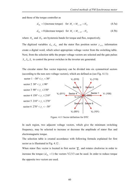
The circular stator flux vector trajectory can be divided into six symmetrical sectors<br />
(according to the non zero voltage vectors), which are defined as (see Fig. 4.11):<br />
sector 1 − 30°≤ γ s<br />
< 30°<br />
V 3 (010)<br />
V 2 (110)<br />
sector 2 30°< γ s<br />
≤ 90°<br />
sector 3 90°< γ s<br />
≤ 150°<br />
sector 4 150°< γ s<br />
≤ 210°<br />
sector 5 210°< γ s<br />
≤ 270°<br />
sector 6 270°< γ s<br />


![[TCP] Opis układu - Instytut Sterowania i Elektroniki Przemysłowej ...](https://img.yumpu.com/23535443/1/184x260/tcp-opis-ukladu-instytut-sterowania-i-elektroniki-przemyslowej-.jpg?quality=85)
