

Direct Torque Control with Space Vector Modulation (DTC-SVM) of ...
Direct Torque Control with Space Vector Modulation (DTC-SVM) of ...
Direct Torque Control with Space Vector Modulation (DTC-SVM) of ...

You also want an ePaper? Increase the reach of your titles
YUMPU automatically turns print PDFs into web optimized ePapers that Google loves.
<strong>Control</strong> methods <strong>of</strong> PM Synchronous motor<br />
Chapter 4 CONTROL METHODS OF PM SYNCHRONOUS MOTOR<br />
4.1 Introduction<br />
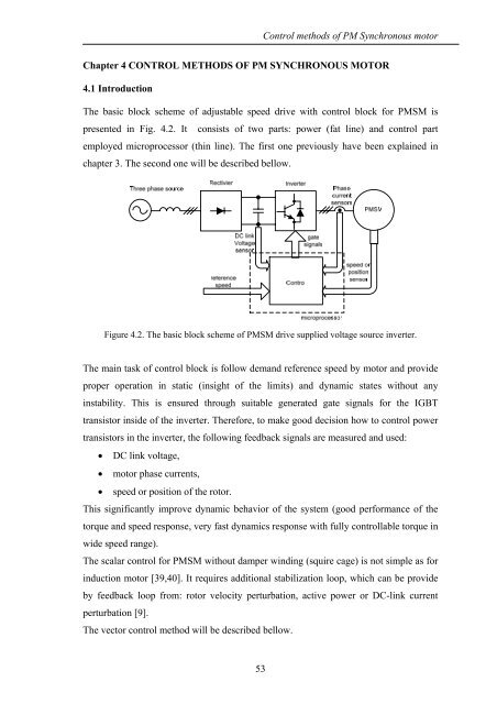
The basic block scheme <strong>of</strong> adjustable speed drive <strong>with</strong> control block for PMSM is<br />
presented in Fig. 4.2. It consists <strong>of</strong> two parts: power (fat line) and control part<br />
employed microprocessor (thin line). The first one previously have been explained in<br />
chapter 3. The second one will be described bellow.<br />
Figure 4.2. The basic block scheme <strong>of</strong> PMSM drive supplied voltage source inverter.<br />
The main task <strong>of</strong> control block is follow demand reference speed by motor and provide<br />
proper operation in static (insight <strong>of</strong> the limits) and dynamic states <strong>with</strong>out any<br />
instability. This is ensured through suitable generated gate signals for the IGBT<br />
transistor inside <strong>of</strong> the inverter. Therefore, to make good decision how to control power<br />
transistors in the inverter, the following feedback signals are measured and used:<br />
• DC link voltage,<br />
• motor phase currents,<br />
• speed or position <strong>of</strong> the rotor.<br />
This significantly improve dynamic behavior <strong>of</strong> the system (good performance <strong>of</strong> the<br />
torque and speed response, very fast dynamics response <strong>with</strong> fully controllable torque in<br />
wide speed range).<br />
The scalar control for PMSM <strong>with</strong>out damper winding (squire cage) is not simple as for<br />
induction motor [39,40]. It requires additional stabilization loop, which can be provide<br />
by feedback loop from: rotor velocity perturbation, active power or DC-link current<br />
perturbation [9].<br />
The vector control method will be described bellow.<br />
53


![[TCP] Opis układu - Instytut Sterowania i Elektroniki Przemysłowej ...](https://img.yumpu.com/23535443/1/184x260/tcp-opis-ukladu-instytut-sterowania-i-elektroniki-przemyslowej-.jpg?quality=85)
