Direct Torque Control with Space Vector Modulation (DTC-SVM) of ...
Direct Torque Control with Space Vector Modulation (DTC-SVM) of ...
Direct Torque Control with Space Vector Modulation (DTC-SVM) of ...
You also want an ePaper? Increase the reach of your titles
YUMPU automatically turns print PDFs into web optimized ePapers that Google loves.
Voltage source PWM inverter for PMSM supply<br />
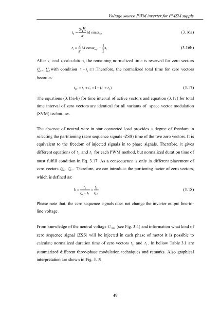
2 3<br />
t2<br />
= Msinα<br />
ref<br />
(3.16a)<br />
π<br />
3 1<br />
t1 = M cosαref<br />
− t2<br />
(3.16b)<br />
π<br />
2<br />
After t 1<br />
and t 2<br />
calculation, the remaining normalized time is reserved for zero vectors<br />
U<br />
0<br />
, U7<br />
<strong>with</strong> condition t 1<br />
+ t 2<br />
≤ 1.Therefore, the normalized total time for zero vectors<br />
becomes:<br />
t = t + t = 1 − ( t + t )<br />
(3.17)<br />
07 0 7 1 2<br />
The equations (3.15a-b) for time interval <strong>of</strong> active vectors and equation (3.17) for total<br />
time interval <strong>of</strong> zero vectors are identical for all variants <strong>of</strong> space vector modulation<br />
(<strong>SVM</strong>) techniques.<br />
The absence <strong>of</strong> neutral wire in star connected load provides a degree <strong>of</strong> freedom in<br />
selecting the partitioning (zero sequence signals -ZSS) time <strong>of</strong> the two zero vectors. It is<br />
equivalent to the freedom <strong>of</strong> injected signals in to phase signals. Therefore, it gives<br />
different equations <strong>of</strong> t 0<br />
and t 7<br />
for each PWM method, but normalized duration time <strong>of</strong><br />
must fulfill condition in Eq. 3.17. As a consequence is only in different placement <strong>of</strong><br />
zero vectors U<br />
0<br />
, U<br />
7<br />
. Therefore, we can introduce the portioning factor <strong>of</strong> zero vectors,<br />
which is defined as:<br />
t t<br />
k = =<br />
t + t t<br />
7 7<br />
0 7 07<br />
(3.18)<br />
Please note that, the zero sequence signals does not change the inverter output line-toline<br />
voltage.<br />
From knowledge <strong>of</strong> the neutral voltage U<br />
N 0<br />
(see Fig. 3.4) and information what kind <strong>of</strong><br />
zero sequence signal (ZSS) will be injected in each phase <strong>of</strong> motor it is possible to<br />
calculate normalized duration time <strong>of</strong> zero vectors t 0<br />
and t 7<br />
. In bellow Table 3.1 are<br />
summarized different three-phase modulation techniques and remarks. Also graphical<br />
interpretation are shown in Fig. 3.19.<br />
49


![[TCP] Opis układu - Instytut Sterowania i Elektroniki Przemysłowej ...](https://img.yumpu.com/23535443/1/184x260/tcp-opis-ukladu-instytut-sterowania-i-elektroniki-przemyslowej-.jpg?quality=85)
