iPU operating instruction - Bedienungsanleitungen / Manuals isel
iPU operating instruction - Bedienungsanleitungen / Manuals isel
iPU operating instruction - Bedienungsanleitungen / Manuals isel

Create successful ePaper yourself
Turn your PDF publications into a flip-book with our unique Google optimized e-Paper software.
Servo – Power Unit<br />
<strong>iPU</strong>-DC<br />
<strong>iPU</strong>-EC<br />
Operating Instruction<br />
<strong>isel</strong> Germany AG, D-36124 Eichenzell, Bürgermeister-Ebert-Str. 40 (06659)981-0 (06659)981-776
<strong>iPU</strong>-DC / <strong>iPU</strong>-EC Operating Instruction<br />
About this <strong>operating</strong> <strong>instruction</strong><br />
Used shortcuts<br />
MRL<br />
ERL<br />
NRL<br />
machine directive 2006/42/EC<br />
EMC directive 2004/108/EC<br />
low voltage directive 73/23/EWC<br />
Used symbols<br />
You will find different symbols in this manual that signalizes important information/<br />
facts and danger.<br />
Warning!<br />
This symbol indicates dangers that cause damages for person’s health,<br />
physical injury or death.<br />
Warning! Dangerous voltage!<br />
Warning of danger from electricity. Ignoring can lead to serious injury or<br />
death.<br />
Attention!<br />
This Symbol indicates important notes. Ignoring this symbol leads to<br />
damages and malfunctions of the machinery<br />
Information:<br />
This symbol indicates important information and notes.<br />
Observe the safety <strong>instruction</strong>s<br />
Before you take the servo power unit <strong>iPU</strong>-DC/<strong>iPU</strong>-EC in operation,<br />
working with the controller or make additions or changes to the<br />
wiring of the, make sure to read carefully the safety <strong>instruction</strong>s in<br />
this manual. (Chapter Fehler! Verweisquelle konnte nicht gefunden<br />
werden. Fehler! Verweisquelle konnte nicht gefunden werden.).
<strong>iPU</strong>-DC / <strong>iPU</strong>-EC Operating Instruction<br />
All information, technical data and dimensions contained in this booklet correspond to<br />
the technical state at the moment of publication. However, possible misprints or<br />
mistakes cannot be ruled out. We will appreciate all suggestions for improvement and<br />
error notes.<br />
We would like to point out that all used software and hardware names of the respective<br />
companies generally are subject to protection by brand, trademark and patent law.<br />
All rights reserved. It is prohibited to process, duplicate or reproduce this booklet<br />
partially or on the whole in any form (print, copy, or other procedure) without written<br />
permission of <strong>isel</strong> Germany AG.<br />
This booklet has been translated from the original German version into English<br />
language. It does not lay claim to completeness nor flawlessness. In case of doubt the<br />
German original has validity.<br />
<strong>isel</strong> controllers are concurrent with CE norms and marked accordingly.<br />
Commissioning of all other parts or components, for which CE safety<br />
regulations apply, is prohibited until all respective requests are met.<br />
<strong>isel</strong> Germany AG as the manufacturer cannot take over guarantee if you<br />
change the controller in any way.<br />
The EMC test is valid only for the controller’s original configuration ex<br />
works, i.e. the delivery state.<br />
Manufacturer:<br />
<strong>isel</strong> Germany AG<br />
Bürgermeister-Ebert-Straße 40<br />
D-36124 Eichenzell<br />
Tel.: (06659) 981-0<br />
Fax: (06659) 981-776<br />
Email: automation@<strong>isel</strong>.com<br />
http://www.<strong>isel</strong>.com<br />
Item-No.:<br />
xxxxxxx<br />
(Translation of operation <strong>instruction</strong> in German language)<br />
State: 7/2012<br />
Technical changes reserved.<br />
Latest <strong>operating</strong> <strong>instruction</strong>s and manuals for download, visit:<br />
www.<strong>isel</strong>-data.de/manuals
<strong>iPU</strong>-DC / <strong>iPU</strong>-EC Operating Instruction<br />
Table of contents<br />
1 Introduction .......................................................................................................... 5<br />
1.1 Intended use .................................................................................................... 5<br />
1.2 Safety <strong>instruction</strong>s............................................................................................ 6<br />
2 Types ..................................................................................................................... 7<br />
3 Technical data ...................................................................................................... 8<br />
4 Hardware description ........................................................................................... 9<br />
4.1 Controller front side <strong>iPU</strong>-DC / <strong>iPU</strong>-EC .............................................................. 9<br />
4.2 Controller back side <strong>iPU</strong>-DC / <strong>iPU</strong>-EC ............................................................11<br />
4.4 Assembly <strong>iPU</strong>-DC / <strong>iPU</strong>-EC ............................................................................18<br />
5 Initial operation ................................................................................................... 19<br />
6 Software .............................................................................................................. 21<br />
6.1 Installing setup software .................................................................................21<br />
6.2 ProNC / Remote installation and first steps ....................................................23<br />
8 EC - Declaration of Conformity ......................................................................... 26<br />
9 Bibiography ........................................................................................................ 27<br />
10 Index .................................................................................................................... 27
<strong>iPU</strong>-DC / <strong>iPU</strong>-EC Operating Instruction<br />
1 Introduction<br />
The <strong>iPU</strong> power units are powerful drive controllers for up to four linear or circular<br />
axes with brush or brushless motors. The compact controller integrates all<br />
necessary controller components, which are needed to solve a wide range of<br />
automation tasks. These range from iMD10 or iMD20 final output stages through<br />
the I/O module to safety control and power electronics.<br />
As its interface for NC control, the <strong>iPU</strong> power unit has a CANopen interface at<br />
the back of the housing, which works according to the DS301 bus protocol and<br />
DS402. By using the optional CAN PCI board iCC 10 or a iPC series control<br />
computer, the controller can control interpolation (linear, circular, helical) of all four<br />
axes as well as track processing.<br />
The final output stages (iMD10 or iMD20) also have automatic jerk limitations<br />
and rest state monitoring.<br />
The control elements integrated in the front of the housing, such as EMERGENCY<br />
SHUTDOWN, START or STOP enable convenient operation.<br />
1.1 Intended use<br />
Die control unit <strong>iPU</strong>-DC/<strong>iPU</strong>-EC integrates motor power amplifiers, I/O module and<br />
security circuit module.<br />
The power units have to be used in connection with an <strong>isel</strong> CANopen PCI-card<br />
(iCC10, iCC20) that works as CAN master in the control computer. The card<br />
communicates with the power amplifiers for the axes and other CAN peripheral<br />
devices such as I/O-module. The CNC Motion control allows the interpolation of up<br />
to 4 axes (linear, circular and helix), on-line and look ahead continuous path (CP)<br />
machining as well as the control of up to 4 handling axes.<br />
The CAN-servo units series <strong>iPU</strong>-DC are able to drive up to 4 brushed DC-servomotors.<br />
The used power amplifiers type iMD10 have a jerk limit and standstill<br />
monitoring (till safety category 3).<br />
Control units series <strong>iPU</strong>-EC are able to drive up to46 brushless DC-servo-motors.<br />
The used power amplifiers type iMD20 have a jerk limit and standstill monitoring (till<br />
safety category 3).<br />
All axis of the controller have to be used only with the compatible motor type.<br />
Please read this operation <strong>instruction</strong> manual carefully before first use of the<br />
controller therewith you can:<br />
• Work safely, fast and effective<br />
• Keep away danger from persons<br />
• Use all the power and features of the controller.<br />
page - 5
<strong>iPU</strong>-DC / <strong>iPU</strong>-EC Operating Instruction<br />
1.2 Safety <strong>instruction</strong>s<br />
• The CNC-controllers <strong>iPU</strong>-DC and <strong>iPU</strong>-EC are designed in<br />
conformability to current technical and recognized rules.<br />
• The device may only be used if it is in correct condition. Any faults<br />
have to be eliminated immediately. Neither children nor nonauthorized<br />
persons are allowed to put the device into operation.<br />
• The device may only be used for the intended purpose: control of 2<br />
up to 6 linear or rotational axes with brushed DC Servo (<strong>iPU</strong>-DC) or<br />
brushless DC servo motors (<strong>iPU</strong>-EC), both motor types with<br />
integrated incremental measurement system (encoder).<br />
• All work with the controllers <strong>iPU</strong>-DC and <strong>iPU</strong>-EC, especially initial<br />
operation, installation as well as external wiring must be executed by<br />
authorized personal regarding electrical industry rules and accident<br />
prevention regulations.<br />
• Assembly and use of <strong>operating</strong> material has to be according to<br />
Machine directive 98/37/EC (valid until 28/12/2009) resp. 2006/42/EC<br />
(becomes operative from 29/12/2009) and Low voltage directive<br />
73/23/EWC. In case of in proper use even the observation of the<br />
respective rules and standards does not protect against physical<br />
damages and damage to property.<br />
• Do not expose the device to high humidity or high vibrations.<br />
• Please take care of the <strong>instruction</strong> manual. Be sure that all users<br />
know the <strong>instruction</strong>s.<br />
• Ignoring the <strong>instruction</strong> manual can lead to damage, heavy physical<br />
damage or to death.<br />
page - 6
<strong>iPU</strong>-DC / <strong>iPU</strong>-EC Operating Instruction<br />
2 Types<br />
type servo motor amplifiers max. axis<br />
<strong>iPU</strong>-DC BDC-servo motors (brushed) iMD10 4<br />
<strong>iPU</strong>-EC BLDC-servo motors (brushless) iMD20 4<br />
Scope of delivery <strong>iPU</strong>-DC (part.-no. 353000 X 1 01X 2 )<br />
<br />
Power unit <strong>iPU</strong>-DC as table housing or 19“ 4 HE housing with the following<br />
electronic components:<br />
o max 4 integrated power amplifiers iMD10 for<br />
brushed DC servo motors /1/<br />
o CAN IO 8-12 / 4-1 module<br />
o Safety circuit module iSM5<br />
o power unit 24V-60W, 48V-1000W<br />
main lead (protection contact plug, IEC-60320 power connector)<br />
<br />
CAN bus connection cable, RJ45 plugplug<br />
connector package<br />
control software Remote from Version 1.46.2.1 (optional: ProNC)<br />
<br />
<strong>operating</strong> <strong>instruction</strong> in printed form<br />
Scope of delivery <strong>iPU</strong>-EC (Art.-Nr. 353000 X 1 02X 2 )<br />
<br />
Power unit <strong>iPU</strong>-DC as table housing or 19“ 4 HE housing with the following<br />
electronic components:<br />
o max 4 integrated power amplifiers iMD20 for<br />
brushed DC servo motors /1/<br />
o CAN IO 8-12 / 4-1 module<br />
o Safety circuit module iSM5<br />
o power unit 24V-60W, 48V-1000W<br />
main lead (protection contact plug, IEC-60320 power connector)<br />
<br />
CAN bus connection cable, RJ45 plugplug<br />
connector package<br />
control software Remote from Version 1.46.2.1 (optional: ProNC)<br />
<br />
<strong>operating</strong> <strong>instruction</strong> in printed form<br />
1 case 1 … 19“ 4HE housing, 2 … table housing<br />
2 Number of axis: 2 …4<br />
page - 7
<strong>iPU</strong>-DC / <strong>iPU</strong>-EC Operating Instruction<br />
3 Technical data<br />
controller <strong>iPU</strong>-DC <strong>iPU</strong>-EC<br />
servo-motor type BDC servo motors (DC brushed) BLDC servo motors (DC brushless)<br />
maximum number of axis 4 4<br />
power supply 100 - 230 VAC, 50 … 60 Hz 100 - 230 VAC, 50 … 60 Hz<br />
power supply output 1000 W 1000 W<br />
motor power amplifier iMD10 iMD20<br />
intermediate circuit power<br />
supply<br />
48 VDC 48 VDC<br />
rated current 12 A 12 A<br />
peak current 25 A 25 A<br />
safety characteristic:<br />
additional safety functions<br />
I/O module<br />
control elements<br />
control software<br />
EN ISO 13849-1:2006 category 3, PL d<br />
integration in higher ranked security circuit , safety door control, working spindle control<br />
4 x digital inputs (24VDC/8mA)<br />
8 x digital outputs (4 x electronic Imax
<strong>iPU</strong>-DC / <strong>iPU</strong>-EC Operating Instruction<br />
4 Hardware description<br />
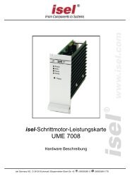
4.1 Controller front side <strong>iPU</strong>-DC / <strong>iPU</strong>-EC<br />
1 - operation mode switch (key switch)<br />
Use this switch to choose between automatic- and setup-mode.<br />
In automatic-mode you can only open the cover or safety door of<br />
the machine if no axis is in motion and the mounted working<br />
spindle is switched off (means that spindle does not turn).<br />
In the setup-mode you can only open the cover or safety door of<br />
the machine if the mounted working spindle is switched off<br />
(means that spindle does not turn). You can just move the axes at<br />
opened cover or safety door if you press the ACK button.<br />
Ensure that in setup-mode (key switch on TEST) only authorized<br />
personal operates on the machine.<br />
2 - cover-button<br />
Use this button to open the machines cover or safety door. This is possible only if the<br />
conditions from point “3 – operation mode switch“ are complied. An enable for<br />
opening of the cover or safety door is signalized by a white lighted cover button.<br />
3 - start-button<br />
If you press the start button an opened user program in the operator software ProNC<br />
(ISO-, PAL- or NCP-file) resp. user program in control software Remote (ISO-, NCPor<br />
CNC-file) will be started.<br />
If there is no user program opened a dialog window is shown where you<br />
can select an user program.<br />
4 - fault-lamp<br />
The fault lamp indicates an error within the safety circuit.<br />
page - 9
<strong>iPU</strong>-DC / <strong>iPU</strong>-EC Operating Instruction<br />
5 - ACK (ACKnowledge-button)<br />
Press this button to move the axes when the machine is in setup-mode and the<br />
cover or safety door is open.<br />
6 - stop-button<br />
With the stop button you can stop a running user program / axis motion. By pressing<br />
the start button you can continue the execution of the user program.<br />
7 - power-button<br />
Use this button to switch on motor power supply voltage for the motor power<br />
amplifiers.<br />
Conditions for switch on:<br />
- Main power switch on the controller back side is switched on<br />
- Emergency stop button is pulled out<br />
If power supply voltage is successfully switched on the power button is lighted green.<br />
8 - emergency-stop-switch<br />
Turns off the power supply for the motor power amplifiers and the working spindle in<br />
case of any danger. This means dangers for the users health or machine safety. The<br />
integrated security circuit is applicable till safety category 3 (DIN EN945-1).<br />
If you push the emergency stop switch any axes motion will be slow<br />
down controlled and the motor power supply will be time lag<br />
switched off (stop category 1).<br />
The main power supply voltage of 115/230VAC lies still on the<br />
device, only the motor power supply voltage for the amplifiers is<br />
switched off.<br />
Main switch (if mounted)<br />
Switch on net power supply voltage for the controller. The switch is lighted green if<br />
device is powered.<br />
page - 10
<strong>iPU</strong>-DC / <strong>iPU</strong>-EC Operating Instruction<br />
4.2 Controller back side <strong>iPU</strong>-DC / <strong>iPU</strong>-EC<br />
➀ Connectors for motor-, encoder- and signal leads<br />
<strong>iPU</strong>-DC - motor, encoder and signal leads<br />
motor connector (X, Y, Z, A, B, C), 8+1-pin M23 socket<br />
pin signal lead no. description<br />
1 1 1 motor phase 1*<br />
2 2 2 motor phase 2*<br />
3 1 3 motor phase 1*<br />
4 2 4 motor phase 2*<br />
5 brake brown motor brake<br />
6 brake_GND white motor brake GND<br />
7 ---<br />
8 ---<br />
9 PE yellow / green protected earth<br />
* every motor phase is connected via two leads<br />
encoder / signal connector, 15-pin Sub-D socket<br />
pin signal lead color description<br />
1 n.c<br />
2 VCC_Encoder red digital +5V DC<br />
3 /ENC_Z orange / black encoder line /Z<br />
4 /ENC_B brown / black encoder line /B<br />
5 /ENC_A grey / black encoder line /A<br />
6 VCC_Logik logic +24V DC<br />
7 LIMIT_SW1 limit switch 1<br />
8 GND_24V Logik GND<br />
9 n.c white Hall signal B<br />
10 D_GND black digital GND<br />
11 ENC_Z orange encoder line Z<br />
12 ENC_B brown encoder line B<br />
13 ENC_A grey encoder line A<br />
14 REF_SW reference switch<br />
15 LIMIT_SW2 limit switch 2<br />
page - 11
<strong>iPU</strong>-DC / <strong>iPU</strong>-EC Operating Instruction<br />
<strong>iPU</strong>-EC - motor, encoder and signal leads<br />
motor connector (X, Y, Z, A, B, C), 8+1-pin M23 socket<br />
pin signal lead no. description<br />
1 U black 1 motor phase U<br />
2 V black 2 motor phase V<br />
3 W black 3 motor phase W<br />
4 ---<br />
5 brake brown motor brake<br />
6 brake_GND white motor brake GND<br />
7 ---<br />
8 ---<br />
9 PE yellow / green protected earth<br />
encoder / signal connector, 15-pin Sub-D socket<br />
pin signal lead no. description<br />
1 HALL_A _IN yellow Hall Signal A<br />
2 VCC_Encoder red Digital +5V DC<br />
3 /ENC_Z orange / black Encoderspur /Z<br />
4 /ENC_B brown / black Encoderspur /B<br />
5 /ENC_A grey / black Encoderspur /A<br />
6 VCC_Logik Logik +24V DC<br />
7 LIMIT_SW1 Endlagenschalter 1<br />
8 GND_24V Logik GND<br />
9 HALL_B_IN white Hall Signal B<br />
10 D_GND black Digital GND<br />
11 ENC_Z orange Encoderspur Z<br />
12 ENC_B brown Encoderspur B<br />
13 ENC_A grey Encoderspur A<br />
14 HALL_C_IN green Hall Signal C<br />
15 LIMIT_SW2 Endlagenschalter 2<br />
page - 12
<strong>iPU</strong>-DC / <strong>iPU</strong>-EC Operating Instruction<br />
➁ hand control unit - 25-pin Sub-D (optional version)<br />
This connector is only available on controller without integrated function keys in the<br />
case front.<br />
It is possible to connect function keys (switches, buttons) from:<br />
- an external hand control unit<br />
- an <strong>isel</strong> CNC control panel<br />
with the corresponding connectors on the security circuit module inside the controller<br />
case.<br />
pin signal<br />
description<br />
1 E-STOP_1 Emergency stop channel 1, 1.1<br />
2 E-STOP _1 Emergency stop channel 1, 1.2<br />
3 E-STOP _2 Emergency stop channel 2, 2.1<br />
4 E-STOP _2 Emergency stop channel 2, 2.2<br />
5 24V +24 V DC<br />
6 POWER BTN Input power button<br />
7 POWER LAMP Output power button lamp<br />
8 24V +24VDC<br />
9 KEY SWITCH Test Input key switch test mode<br />
10 KEY SWITCH Auto Input key switch automatic mode<br />
11 24V +24VDC<br />
12 ACK_1 Input acknowledge button channel1<br />
13 24V +24VDC<br />
14 ACK_2 Input acknowledge button channel 2<br />
15 COVER SWITCH Input cover button<br />
16 COVER SWITCH Input cover button<br />
17 GND<br />
18<br />
19<br />
20 FAULT LAMP output FAULT lamp<br />
21 START BTN Input START button (make contact)<br />
22 STOP BTN Input STOP button (break contact)<br />
23 START LAMP Output START lamp<br />
24 STOP LAMP Output STOP lamp<br />
25 n.v.<br />
The maximum length of the connection cable for the hand control<br />
unit / CNC control panel should not exceed 5m.<br />
page - 13
<strong>iPU</strong>-DC / <strong>iPU</strong>-EC Operating Instruction<br />
➂ External additional control console connector - 15-pin Sub-D (optional)<br />
This connector is used if an additional <strong>isel</strong> control console is used.<br />
pin signal<br />
description<br />
1 EM_STOP_1 Emergency stop channel 1, connector 1.1<br />
2 EM_STOP_1 Emergency stop channel 1, connector 1.2<br />
3 EM_STOP_2 Emergency stop channel 2, connector 2.1<br />
4 EM_STOP_2 Emergency stop channel 2, connector 2.1<br />
5 GND GND control console<br />
6 LAMP ACK Output ACK lamp<br />
7 ACK_1 Acknowledge channel 1, connector 1.1<br />
8 ACK_1 Acknowledge channel 1, connector 1.2<br />
9 ACK_2 Acknowledge channel 2, connector 2.1<br />
10 ACK_2 Acknowledge channel 2, connector 2.2<br />
11 COVER_1 Connector for cover button, connector 1.1<br />
12 COVER_1 Connector for cover button, connector 1.2<br />
13 COVER_2 Connector for cover button, connector 2.1 (option)<br />
14 COVER_2 Connector for cover button, connector 2.1 (option)<br />
15 n.v.<br />
The maximum length of the connection cable for the hand control<br />
unit / CNC control panel should not exceed 5m.<br />
➃ External Spindle – SubD-9-pin<br />
Use this connetor to get the signals for driving an external frequency converter for an<br />
main spindle drive.<br />
pin signal description<br />
1 VCC +24V DC<br />
2 SPINDLE_FAULT Input frequency converter fault (LOW activ)<br />
3 - n.u.<br />
4 - n.u.<br />
5 ANALOG_OUT analog out 0 …10V (8 bit resolution)<br />
6 ANALOG_GND analog GND<br />
7 - n.u.<br />
8 SPINDLE_START uutput spindle start<br />
9 GND GND (digital)<br />
page - 14
<strong>iPU</strong>-DC / <strong>iPU</strong>-EC Operating Instruction<br />
➄ Digital input port - 8-pin, bottom to top E1.1 – E1.4<br />
The mounted I/O board has two digital input ports each with 8 digital inputs. The first<br />
input port (E1.1 – E1.8) is partly internal used for signalization. The digital inputs<br />
E1.1 – E1.4 can free configured by the user.<br />
Properties<br />
- opt coupled inputs<br />
- input current ca. 8mA<br />
Wiring<br />
pin input description<br />
1 In 1 input E1.1<br />
2 VCC +24VDC<br />
3 In 2 input E1.2<br />
4 VCC +24VDC<br />
5 In 3 input E1.3<br />
6 VCC +24VDC<br />
7 In 4 input E1.4<br />
8 VCC +24VDC<br />
Please note the default connection of the second input –port (I1.5 – I1.8)<br />
in the control software Remote / ProNC under the menu entry<br />
„Signalization“.<br />
These inputs are directly wired with the modules inside the<br />
controller. You cannot longer use these inputs in the user program!<br />
➅ Digital electronic outputs - 8-pin, bottom to top A1.1 – A1.4<br />
The mounted I/O board has two digital output ports each with 8 digital switches. The<br />
first output port (A1.1 – A1.8) is partly internal used for signalization. The outputs<br />
A1.1 – A1.4 can used to switch different actors.<br />
Properties<br />
- 8 x electronic outputs<br />
- Imax < 350mA, 24VDC<br />
- Thermic protection<br />
- short circuit proof<br />
Wiring<br />
pin output description<br />
1 Out1 Output A1.1<br />
2 GND GND<br />
3 Out2 output A1.2<br />
4 GND GND<br />
5 Out3 Output A1.3<br />
6 GND GND<br />
7 Out4 Output A1.4<br />
8 GND GND<br />
page - 15
<strong>iPU</strong>-DC / <strong>iPU</strong>-EC Operating Instruction<br />
Please note the default connection of the first output –port (A1.1 – A1.8)<br />
in the control software Remote / ProNC under the menu entry<br />
„Signalization“.<br />
These outputs are directly wired with the modules inside the<br />
controller. You cannot longer use these outputs in the user<br />
program!<br />
➆ Digital relay outputs - 8-pin, bottom to top A2.1 – A2.4<br />
The mounted I/O board has a second digital output port with four other relay<br />
outputs. The second output port (A2.1 – A2.8) is partly internal used. The outputs<br />
A2.1 – A2.4 can freely used to switch different actors.<br />
Properties<br />
- 4 x digital rely outputs<br />
- Imax < 5 A, 24VDC<br />
- Thermic protection<br />
- short circuit proof<br />
Wiring<br />
pin output description<br />
1 Out1 Output A2.1<br />
2 GND GND<br />
3 Out2 output A2.2<br />
4 GND GND<br />
5 Out3 Output A2.3<br />
6 GND GND<br />
7 Out4 Output A2.4<br />
8 GND GND<br />
➇ Remote- security circuit interface, 8-pin, bottom to top<br />
Use this connector to include the controller into a higher ranked security circuit<br />
system. Furthermore, this interface provides the functions of the front control buttons<br />
(START, STOP) as a function of an external remote control panel or other device via<br />
I / O functions.<br />
pin signal description<br />
1 E_STOP_1_1 external emergency STOP, channel 1, connector 1.1<br />
2 E_STOP_1_2 external emergency STOP, channel 1, connector 1.2<br />
3 E_STOP_2_1 external emergency STOP, channel 2, connector 2.1<br />
4 E_STOP_2_2 external emergency STOP, channel 2, connector 2.2<br />
5 EXT_START external START button (option to E1.7 on CAN IO)<br />
6 EXT_STOP external STOP button (option to E1.8 on CAN IO)<br />
7 VCC +24V for switches<br />
8 VCC +24V for switches<br />
page - 16
<strong>iPU</strong>-DC / <strong>iPU</strong>-EC Operating Instruction<br />
➈ AC-Input – net input module 115 -230 VAC, 50 …60 Hz<br />
The net input module consists of net input socket, net filter, fuse holder and net main<br />
switch. Connect the controller via delivered net cable to a free receptacle. After that<br />
you can switch on the controller with the net main switch.<br />
➉ Spindle -115V/ 230V connector<br />
Use this output connector to directly tap a working spindle without speed control.<br />
Use the delivered mating connector. Maximum load of the relay output is 115/230 V<br />
AC / 6A. The spindle start signal is switched by the integrated CAN-I/O-module and<br />
will be analyzed by the security-circuit-module (iSM5). If all safety related conditions<br />
are complied the 115/230 V AC voltage is switched on the connector.<br />
Please note the pin assignment for the spindle start signal in<br />
the table for the CAN-I/O-module in chapter 4.2.4.2<br />
The net input module consists of net input socket, net filter, fuse holder und net main<br />
switch. Connect the controller via delivered net cable to a free receptacle. After that<br />
you can switch on the controller with the net main switch.<br />
11 Cover - Sub-D9-pin connector<br />
This connector is used to integrate a solenoid interlock to the security circuit of the<br />
controller.<br />
On <strong>isel</strong> machines the solenoid interlock is realized by a switch of<br />
type:<br />
SCHMERSAL EX-AZM 170-02ZK-24V (part-no. 577047 0800)<br />
Only this type interlocks or interlocks with the same functionality<br />
have to be used.<br />
pin description<br />
1 + coil break contact<br />
2 switch 1.1 (bridge to pin 3 if no safety door is used)<br />
3 switch 1.2 (bridge to pin 2 if no safety door is used<br />
4 switch 2.1 (bridge to pin 5 if no safety door is used<br />
5 switch 2 .2 (bridge to pin 4 if no safety door is used<br />
6 - coil break contact<br />
7 - 9 n.u.<br />
If no cover or safety door is used the pins 2, 3 and 4, 5 must be<br />
bridged. Therefore use the enclosed Sub-D 9-pin plug.<br />
If the contacts of the interlock is interrupted (e.g. forcible opening of<br />
the hood or remove the jumper, Sub-D) will immediately trigger an<br />
emergency stop and turned off the spindle.<br />
page - 17
<strong>iPU</strong>-DC / <strong>iPU</strong>-EC Operating Instruction<br />
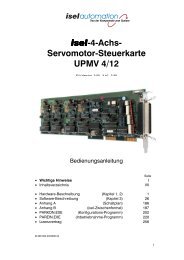
4.4 Assembly <strong>iPU</strong>-DC / <strong>iPU</strong>-EC<br />
CAN I/O-8/12-4/1<br />
I/O module<br />
Chopper module with<br />
brake resistor<br />
E/A Modul<br />
power supply unit 100-<br />
230VAC, 48V DC 1000W<br />
für Endstufen<br />
Netzt power supply unit<br />
100-230VAC,<br />
24V DC 60W for logic<br />
power amplifier<br />
iMD10 on <strong>iPU</strong>-DC<br />
for brushed DC<br />
servo-motors<br />
iSM 5 security circuit<br />
module<br />
iMD20 on <strong>iPU</strong>-EC<br />
for brushless DC<br />
servo-motors<br />
function keys module<br />
for control elements<br />
(buttons, switches) on the<br />
front side of the controller<br />
page - 18
<strong>iPU</strong>-DC / <strong>iPU</strong>-EC Operating Instruction<br />
5 Initial operation<br />
Voraussetzungen für den Betrieb des Controllers<br />
Die Leistungseinheiten <strong>iPU</strong>-DC / <strong>iPU</strong>-EC verfügen über intelligente CAN Module wie<br />
bspw. Leistungsendstufen zur Steuerung von Motoren.<br />
Für die Kommunikation mit den Modulen benötigen Sie einen CAN Master<br />
Controller iCC10 (Art.-Nr. 320310) oder iCC20 (Art.-Nr. 320310) als PCI<br />
Einsteckkarte. Stecken Sie die PCI Karte iCC10 / iCC20 in einen freien PCI<br />
Steckplatz in Ihrem PC. Die Treiber für die CAN PCI Karte befindet sich auf dem<br />
Datenträger mit den Installationsdateien von ProNC/Remote im Verzeichnis:<br />
{root:}\Control\CAN\CAN_PCI_Driver_1_Channel<br />
In den Unterverzeichnissen befinden sich die Treiber für verschiedene Windows<br />
Betriebssysteme. Beim Starten des Rechners werden Sie aufgefordert den zu<br />
installierenden Treiber auswählen. Alternativ können Sie den Treiber auch über den<br />
Gerätemanager des Betriebssystems installieren.<br />
Preparation<br />
Before power up of the controller please check the scope of delivery.<br />
Following parts should be included:<br />
- net cable<br />
- <strong>operating</strong> <strong>instruction</strong><br />
- CAN bus communication cable RJ45 plug RJ45 plug<br />
Make all necessary connections:<br />
- connect net cable<br />
- connect motor- and encoder-lines (motors) with the connectors on the back<br />
side of the controller<br />
- connect communication cable between CAN PCI card and controller <strong>iPU</strong>-<br />
DC/<strong>iPU</strong>-EC<br />
- check all other connection cables<br />
page - 19
<strong>iPU</strong>-DC / <strong>iPU</strong>-EC Operating Instruction<br />
Initial operation<br />
- switch on controller main switches on front side and back side<br />
the main switch on the front side should be lighted green<br />
- install control software (if not preinstalled)<br />
• ProNC (1) or Remote<br />
- install setup software (if not preinstalled)<br />
• DCSetup (2)<br />
• ACSetup (1)<br />
- check if Emergency stop switch is pulled<br />
- push Power button on the controller front side – motor power amplifier voltage<br />
should be switched on<br />
- parameterize power amplifiers with ACSetup.exe / DCSetup.exe<br />
- setup axes kinematic of your machine/system with CANSet.exe<br />
- Control/operate the connected axes with the control- and programming<br />
software ProNC or Remote<br />
page - 20
<strong>iPU</strong>-DC / <strong>iPU</strong>-EC Operating Instruction<br />
6 Software<br />
6.1 Installing setup software<br />
Setup / initial operation of the integrated power amplifiers inside the controller’s iMC-<br />
B, iMC-V and iMC-VP takes place by the following setup software<br />
DCSetup.exe (4)<br />
for:<br />
- BDC-servo-motors (brushed-DC-servos) with motor power<br />
amplifiers iMD10<br />
or<br />
for:<br />
ACSetup.exe (2)<br />
- BLDC-servo-motors (brushless-DC-servos) with motor power<br />
amplifiers iMD20<br />
Do the following steps to install setup software additional:<br />
1. Connect ProNC/Remote install medium (delivered CD or USB stick) with the<br />
control computer.<br />
2. Following Auto-start-window will be shown (when installing from CD):<br />
If Auto-Start-window is not shown start the Windows Explorer<br />
and open the root directory of the CD/DVD- or USB-drive.<br />
Double click on the file “Autorun.exe“.<br />
page - 21
<strong>iPU</strong>-DC / <strong>iPU</strong>-EC Operating Instruction<br />
3. Click on the entry “Installation of control software“. The following window will be<br />
shown:<br />
Choose now the setup software depending on your motor type and click on the<br />
entry to start the installation. (in this example “Installation of ACSetup“)<br />
Follow the <strong>instruction</strong>s of the setup assistant.<br />
After finishing the installation click on button “Exit“ to close the Auto-Start-menu.<br />
Start DCSetup.exe / ACSetup.exe via the desktop shortcut or via the start menu<br />
entry:<br />
Start Programs ACSetup ACSetup / DCSetup<br />
Information on parameterization of motor power amplifiers iMD10 you<br />
will find in the manual /1/ DC-Servo positioning module with<br />
CANopen interface UVE8112 / iMD10. Therefore open the file<br />
“dcsetup_eng.pdf “ via shortcut in the start menu.<br />
Information on parameterization of motor power amplifiers iMD20 you<br />
will find in the manual /2/ AC-Servo positioning module with<br />
CANopen interface iMD20 / iMD40. Therefore open the file<br />
“acsetup_eng.pdf “ via shortcut in the start menu.<br />
page - 22
<strong>iPU</strong>-DC / <strong>iPU</strong>-EC Operating Instruction<br />
6.2 ProNC / Remote installation and first steps<br />
Operation of the controller iMC-B / iMC-V takes place either with the control software<br />
Remote or with the control / programming software ProNC.<br />
If there is no operation software installed ex factory do the following steps to install<br />
the software later:<br />
1. Connect ProNC / Remote install medium (delivered CD or USB stick) with the<br />
control computer.<br />
2. Following Auto-start-window will be shown (when installing from CD):<br />
If Auto-Start-window is not shown start the Windows Explorer<br />
and open the root directory of the CD/DVD- or USB-drive.<br />
Double click on the file “Autorun.exe“.<br />
page - 23
<strong>iPU</strong>-DC / <strong>iPU</strong>-EC Operating Instruction<br />
3. Click on the entry “Installation of ProNC“<br />
Choose your language and follow the <strong>instruction</strong>s of the setup assistant.<br />
Mark on setup window “Select control“ the option “CAN-Bus-Control“ to install the<br />
CAN-bus software module.<br />
After finishing the installation click on button “Exit“ to close the Auto-Start-menu.<br />
4. Open the configuration program CANSet.exe (shortcut on windows-desktop or<br />
start-menu-entry: Start Programs <strong>isel</strong> CAN-CNC-Control CANSet) to<br />
setup machine specific parameters (CAN-interface, used axes, axis type).<br />
Save your configuration to an initialization file (*.ini file). The saved file will be<br />
used later in the control software ProNC / Remote as motion control initialization<br />
file.<br />
page - 24
<strong>iPU</strong>-DC / <strong>iPU</strong>-EC Operating Instruction<br />
5. Open the control software ProNC / Remote via shortcut on the windows desktop<br />
or the start menu entry: Start Programs CNCworkbench ProNC/Remote<br />
Click on entry “control“ in menu “settings“. Mark the entry Motion control<br />
modules Axis system 1. In the bottom right side of the window you will find the<br />
settings for the selected axis system. In the edit field “Module initialization file”<br />
you must choose your previously with CANSet.exe generated and saved INI-file.<br />
Click on button “Close & Initialize” to take effect the new settings.<br />
6. Perform a software reset and a reference run to check correct<br />
behavior of the machine /system.<br />
Additional information to configure ProNC / Remote you can<br />
find in the online help (menu help, F1 key).<br />
page - 25
<strong>iPU</strong>-DC / <strong>iPU</strong>-EC Operating Instruction<br />
8 EC - Declaration of Conformity<br />
Der Hersteller<br />
The manufacturer<br />
<strong>isel</strong> Germany AG<br />
Bürgermeister-Ebert-Str. 40<br />
D-36124 Eichenzell<br />
erklärt hiermit, dass folgendes Produkt<br />
hereby declares that the following product<br />
Geräteart:<br />
Device:<br />
Typ:<br />
Type:<br />
<strong>isel</strong> Leistungseinheit<br />
<strong>isel</strong> power unit<br />
<strong>iPU</strong>-DC / <strong>iPU</strong>-EC<br />
Art.-Nr.: <strong>iPU</strong>-DC: 354000 10X0<br />
Product - No.: <strong>iPU</strong>-EC: 354000 20X0<br />
mit den Vorschriften folgender Europäischer Richtlinien übereinstimmt:<br />
complies with the requirements of the European Directives:<br />
EG-Richtlinie 2004/108/EG<br />
EC-Directive 2004/108/EC<br />
EG-Richtlinie 73/23/EWG<br />
EC-Directive 73/23/ECC<br />
EMV Richtlinie<br />
EMC directive<br />
Niederspannungsrichtlinie<br />
low voltage directive<br />
Folgende harmonisierte Normen wurden angewandt:<br />
Following harmonized standards have been applied:<br />
EN 61000-6-2:2005<br />
EN 61000-4-2:2007<br />
EN 61000-4-4:2004<br />
EMV - Fachgrundnorm - Störfestigkeit für Industriebereich<br />
EMC - Generic standards - Immunity for industrial environments<br />
EMV - Prüf- und Messverfahren - Prüfung der Störfestigkeit gegen Entladung<br />
statischer Elektrizität (ESD)<br />
EMC - Testing and measurement techniques; Electrostatic discharge immunity test<br />
EMV - Prüf- und Messverfahren - Prüfung der Störfestigkeit gegen schnelle<br />
transiente elektrische Störgrößen (Burst)<br />
EMC - Testing and measurement techniques - Electrical fast transient/burst immunity test<br />
EN 61000-4-5:2006 EMV - Prüf- und Messverfahren - Prüfung der Störfestigkeit gegen<br />
energiereiche Impulse (Surge)<br />
EMC - Testing and measurement techniques - Surge immunity test<br />
EN 61000-4-11:2004<br />
EN 61000-6-3:2007<br />
DIN EN 55011:2007<br />
Dermbach, 13.01.2009<br />
EMV - Prüf- und Messverfahren - Prüfung der Störfestigkeit gegen<br />
Spannungs-einbrüche / Spannungsunterbrechungen<br />
EMC - Testing and measurement techniques - Voltage dips, short interruptions and voltage<br />
variations immunity tests<br />
EMV - Fachgrundnorm - Störaussendung Wohn- und Geschäftsbereich,<br />
Kleinbetriebe<br />
EMC - emission standard for residential, commercial and light-industrial environments<br />
Industrielle, wissenschaftliche und medizinische Hochfrequenzgeräte (ISM-<br />
Geräte) - Funkstörungen - Grenzwerte und Messverfahren<br />
Industrial scientific and medical (ISM) radio-frequency equipment - Electromagnetic<br />
disturbance characteristics - Limits and methods of measurement<br />
Werner Kister, Vorstand / chairman<br />
page - 26
<strong>iPU</strong>-DC / <strong>iPU</strong>-EC Operating Instruction<br />
9 Bibiography<br />
/1/ <strong>isel</strong> Germany AG.<br />
Positioning module with CANOpen interface UVE8112 / iMD10. 03/2008.<br />
/2/ <strong>isel</strong> Germany AG.<br />
Positioning module with CANOpen interface iMD20 / iMD40. 03/2009.<br />
/3/ <strong>isel</strong> Germany AG.<br />
ProNC <strong>operating</strong> <strong>instruction</strong> 2003.<br />
Operating <strong>instruction</strong>s and manuals for download you can find here:<br />
www.<strong>isel</strong>-data.de/manuals<br />
10 Index<br />
A<br />
ACK 10<br />
ACSetup.exe 21<br />
B<br />
BLDC-Servomotoren 7<br />
brushed 5<br />
C<br />
CANSet.exe 20<br />
control console 14<br />
Cover 17<br />
Cover button 9<br />
D<br />
DCSetup.exe 21<br />
E<br />
Encoder 11, 12<br />
H<br />
harmonisierte Normen 26<br />
I<br />
iMD20 8<br />
Installation software 21<br />
intended use 6<br />
L<br />
Low voltage directive 6<br />
O<br />
Operation mode switch 9<br />
P<br />
ProNC 20<br />
R<br />
Remote 20<br />
S<br />
Software 21<br />
page - 27