Positioning module IMD20, IMD40 - Bedienungsanleitungen ...
Positioning module IMD20, IMD40 - Bedienungsanleitungen ...
Positioning module IMD20, IMD40 - Bedienungsanleitungen ...

Create successful ePaper yourself
Turn your PDF publications into a flip-book with our unique Google optimized e-Paper software.
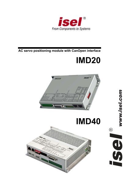
AC servo positioning <strong>module</strong> with CanOpen interface<br />
<strong>IMD20</strong><br />
<strong>IMD40</strong><br />
www.isel.com<br />
®
<strong>Positioning</strong> <strong>module</strong> <strong>IMD20</strong>, <strong>IMD40</strong><br />
Remarks concerning this manual:<br />
D espite the utmost care, print and other errors cannot be excluded.<br />
If you have any suggestions for improvements and hints as regards errors, don’t hesitate to contact us.<br />
Company: isel Germany AG © 2009<br />
All rights reserved.<br />
Without the prior written content of isel Germany AG, no part of this publication may be reproduced,<br />
stored in a retrieval system or transmitted in any way whatsoever.<br />
No responsibility is accepted for the correctness of the data contained in this manual. Isel Germany AG<br />
company reserves the right to make changes to the contents hereof without prior notice.<br />
Prior to the initial use of the servo drive controller you must read the chapters “Safety notes for<br />
electrical drives and controllers” starting on page 8 and “Notes on safe and EMC-compliant<br />
installation” starting on page 15.<br />
Do not try to install or commission the servo drive controller before carefully reading all safety notes for<br />
electrical drives and controllers contained in this document. These safety instructions and all other user<br />
notes must be read prior to any work with the servo drive controller.<br />
Manufacturer: isel Germany AG<br />
Bürgermeister-Ebert-Straße 40<br />
D-36124 Eichenzell<br />
Tel.: (06659) 981-0<br />
Fax: (06659) 981-776<br />
email: automation@isel.com<br />
http://www.isel.com<br />
Last Updated: 05/18/2010
<strong>Positioning</strong> <strong>module</strong> <strong>IMD20</strong>, <strong>IMD40</strong><br />
Table of contents<br />
Table of contents<br />
Table of contents...........................................................................................3<br />
Overview ........................................................................................................7<br />
Features of the drive <strong>module</strong>........................................................................................................ 7<br />
Scope of application..................................................................................................................... 7<br />
Operational environment ............................................................................................................. 8<br />
Safety notes for electrical drives and controllers ......................................9<br />
Used symbols............................................................................................................................... 9<br />
General notes ............................................................................................................................... 9<br />
Danger resulting from misuse.................................................................................................... 10<br />
General safety notes................................................................................................................... 11<br />
Safety notes for assembly and maintenance............................................................................... 12<br />
Protection against contact with electrical parts.......................................................................... 13<br />
Protection against electrical shock by means of protective extra-low voltage (PELV) ............. 14<br />
Protection against dangerous movements .................................................................................. 14<br />
Protection against contact with hot parts ................................................................................... 15<br />
Protection during handling and assembly .................................................................................. 15<br />
Notes on safe and EMC-compliant installation.........................................16<br />
Definition and terms .................................................................................................................. 16<br />
General information on EMC .................................................................................................... 17<br />
EMC-compliant cabling............................................................................................................. 17<br />
Description of the drive <strong>module</strong>.................................................................19<br />
Settings and status display ......................................................................................................... 19<br />
DIP switch ...................................................................................................................... 19<br />
Modes of operation......................................................................................................... 19<br />
LEDs <strong>IMD20</strong>.................................................................................................................. 20<br />
LEDs <strong>IMD40</strong>.................................................................................................................. 21<br />
Hardware description <strong>IMD20</strong> .................................................................................................... 22<br />
Connectors...................................................................................................................... 22<br />
Frame connector X1 – Connection of the operating voltage 40V-95V, motor and<br />
brake................................................................................................................... 22<br />
Frame connector X2 – 15-pin Sub-D – Connection of the encoder, hall sensors<br />
and limit switch................................................................................................... 23<br />
Frame connector X3 – 20 pin – System connection............................................ 23<br />
Frame connector X4 – RJ45 - RS-232 and CAN IN ........................................... 24<br />
Frame connector X5 – RJ45 – CAN OUT .......................................................... 24<br />
Jumper settings ............................................................................................................... 24<br />
Wiring of the inputs and outputs .................................................................................... 24<br />
Digital Inputs limit switch, Enable ..................................................................... 24<br />
Digital output Ready........................................................................................... 25<br />
Digital output Homing........................................................................................ 25<br />
Digital output Brake ........................................................................................... 25<br />
Digital output Limit switch chain ....................................................................... 26<br />
Analogue input.................................................................................................... 26<br />
Encoder connections........................................................................................... 26<br />
CAN .................................................................................................................... 27<br />
Hardware description <strong>IMD40</strong> .................................................................................................... 28<br />
Connectors...................................................................................................................... 28<br />
Frame connector X1 – Connection of the operating voltage AC 220V, motor and<br />
brake................................................................................................................... 28<br />
3
Table of contents<br />
<strong>Positioning</strong> <strong>module</strong> <strong>IMD20</strong>, <strong>IMD40</strong><br />
Frame connector X2 –Connection of operating voltage 24V, temperature and<br />
brake ................................................................................................................... 29<br />
Frame connector X3 – 15-pin Sub-D - Connection encoder, hall sensors, limit<br />
switch .................................................................................................................. 29<br />
Frame connector X4 – 20-pin – System connection............................................ 30<br />
Frame connector X5 – RJ45 - RS-232 und CAN IN............................................ 30<br />
Frame connector X6 – RJ45 – CAN OUT........................................................... 30<br />
Frame connector X7 – Brake resistor................................................................ 31<br />
Jumper settings ............................................................................................................... 31<br />
Wiring of the inputs and outputs..................................................................................... 32<br />
Digital inputs limit switches, reference switch, enable....................................... 32<br />
Digital output Ready........................................................................................... 32<br />
Digital output Homing ........................................................................................ 32<br />
Digital output Brake ........................................................................................... 32<br />
Digital output Limit switch chain........................................................................ 33<br />
Analogue input.................................................................................................... 33<br />
Encoder connections........................................................................................... 34<br />
CAN .................................................................................................................... 34<br />
Data transfer............................................................................................................................... 35<br />
Commissioning .......................................................................................................................... 37<br />
Overview ........................................................................................................................ 37<br />
Particularities as regards the commissioning of a gantry axis ........................................ 37<br />
Examples for the motion control..................................................................................... 37<br />
Example 1:.......................................................................................................... 37<br />
Example 2:.......................................................................................................... 38<br />
Example 3:.......................................................................................................... 40<br />
Fault states ................................................................................................................................. 41<br />
ACSetup programme.................................................................................. 42<br />
Menus......................................................................................................................................... 42<br />
Commands of the File menu........................................................................................... 42<br />
The New command (File menu) .......................................................................... 42<br />
The Open command (File menu)......................................................................... 42<br />
The Save command (File menu).......................................................................... 42<br />
The Save As command (File menu)..................................................................... 42<br />
The 1, 2, 3, 4 commands (File menu).................................................................. 42<br />
The Exit command (File menu)........................................................................... 42<br />
Commands of the Connection menu............................................................................... 43<br />
The Online Mode On/Off command.................................................................... 43<br />
The Active Connection / CAN command............................................................. 43<br />
The Active Connection / RS232 command .......................................................... 43<br />
The RS232 Settings command............................................................................. 43<br />
The CAN Settings command................................................................................ 43<br />
Commands of the Commissioning menu........................................................................ 44<br />
The Step-by-Step Commissioning command ....................................................... 44<br />
The Random Order command............................................................................. 44<br />
The Reset command ............................................................................................ 44<br />
Commands of the Settings menu .................................................................................... 44<br />
The Object Directory command.......................................................................... 44<br />
Commands of the Extra menu......................................................................................... 44<br />
The Extended Functions command ..................................................................... 44<br />
Password............................................................................................................. 44<br />
The Firmware Update / Normal command ......................................................... 45<br />
The Firmware Update / via Bootstrap Loader command ................................... 45<br />
Commands of the View menu......................................................................................... 46<br />
The Tool Bar command....................................................................................... 46<br />
The Status Bar command .................................................................................... 46<br />
The Serial Interface command ............................................................................ 46<br />
The CAN Monitor command ............................................................................... 46<br />
The Drive Status command ................................................................................. 46
<strong>Positioning</strong> <strong>module</strong> <strong>IMD20</strong>, <strong>IMD40</strong><br />
Table of contents<br />
The Language command................................................................................................. 46<br />
Commands of the ? menu ............................................................................................... 46<br />
The Help Topics command ................................................................................. 46<br />
The Info command .............................................................................................. 46<br />
Programme user interface .......................................................................................................... 47<br />
Tool bar .......................................................................................................................... 47<br />
Status bar ........................................................................................................................ 47<br />
Drive status..................................................................................................................... 48<br />
Monitor window for serial interface ............................................................................... 48<br />
Monitor window for CAN communication .................................................................... 49<br />
Programme functions................................................................................................................. 50<br />
Create a data connection................................................................................................. 50<br />
Offline operation................................................................................................. 50<br />
Online operation................................................................................................. 50<br />
Choose Active Connection.................................................................................. 50<br />
RS-232 settings ................................................................................................... 50<br />
CAN settings ....................................................................................................... 51<br />
Commissioning / Adjustment of parameters................................................................... 52<br />
Step-by-step commissioning................................................................................ 52<br />
Random order..................................................................................................... 52<br />
Connection dialogue box .................................................................................... 54<br />
Mode of Operation dialogue box........................................................................ 55<br />
Offset Calibration dialogue box ......................................................................... 56<br />
Analogue Input dialogue box.............................................................................. 57<br />
Brake dialogue box............................................................................................. 58<br />
Current Controller dialogue box ........................................................................ 59<br />
Encoder dialogue box......................................................................................... 61<br />
Motor and Transmission dialogue box ............................................................... 62<br />
Velocity Controller dialogue box........................................................................ 64<br />
Direction dialogue box ....................................................................................... 67<br />
Acceleration dialogue box .................................................................................. 68<br />
Velocity dialogue box ......................................................................................... 69<br />
Position Controller dialogue box ....................................................................... 70<br />
Can Interpolation dialogue box.......................................................................... 73<br />
Inputs dialogue box ............................................................................................ 75<br />
Reference Run dialogue box ............................................................................... 76<br />
Object Directory dialogue box........................................................................................ 77<br />
Firmware update............................................................................................................. 79<br />
CanOpen protocol .......................................................................................80<br />
Overview.................................................................................................................................... 80<br />
SDO ........................................................................................................................................... 82<br />
PDO ........................................................................................................................................... 84<br />
Mapping.......................................................................................................................... 84<br />
Types of transfer............................................................................................................. 85<br />
SYNC......................................................................................................................................... 86<br />
EMCY........................................................................................................................................ 87<br />
Network management - NMT.................................................................................................... 87<br />
Status diagram ................................................................................................................ 88<br />
Boot-Up object ............................................................................................................... 89<br />
Monitoring – Guarding................................................................................................... 89<br />
Object Directory ........................................................................................................................ 91<br />
Communications parameter............................................................................................ 91<br />
General communications parameters................................................................. 91<br />
PDO / Mapping parameters ............................................................................... 95<br />
Device profile parameters............................................................................................. 100<br />
Device control................................................................................................... 100<br />
Mode of operation ............................................................................................ 102<br />
Current control................................................................................................. 103<br />
Profile Position Mode – position control with ramp profile............................. 106<br />
5
Table of contents<br />
<strong>Positioning</strong> <strong>module</strong> <strong>IMD20</strong>, <strong>IMD40</strong><br />
Interpolated Position Mode – Position control with interpolation ................... 108<br />
Homing Mode – Reference run ......................................................................... 110<br />
Moving the axis out of a limit switch ................................................................ 112<br />
Factor Group – Conversion factors.................................................................. 112<br />
General parameters .......................................................................................... 114<br />
Manufacturer-specific parameters ................................................................................ 121<br />
EDS / DCF files ....................................................................................................................... 129<br />
Appendix ................................................................................................... 130<br />
Connection of Motionking EC motor to the <strong>IMD20</strong>, <strong>IMD40</strong> .................................................. 130<br />
Encoder connection....................................................................................................... 130<br />
Motor connection.......................................................................................................... 131<br />
<strong>IMD20</strong> basis connection ............................................................................................... 132<br />
<strong>IMD20</strong> system connection ............................................................................................ 133<br />
<strong>IMD20</strong> package dimensions ......................................................................................... 134<br />
<strong>IMD40</strong> package dimensions ......................................................................................... 135<br />
Glossary .................................................................................................... 137<br />
Index .......................................................................................................... 138
<strong>Positioning</strong> <strong>module</strong> <strong>IMD20</strong>, <strong>IMD40</strong><br />
Overview<br />
Overview<br />
The present manual contains all descriptions and documentations required for the wiring,<br />
commissioning and control of the drive <strong>module</strong>.<br />
It is intended for qualified personnel with basic knowledge of the control and automation technology<br />
as well as of the CAN field bus.<br />
Prior to the initial use of the servo drive controller you must read the chapters “Safety notes for<br />
electrical drives and controllers” starting on page 8 and “Notes on safe and EMC-compliant<br />
installation” starting on page 15.<br />
Do not try to install or commission the servo drive controller before carefully reading all safety notes<br />
for electrical drives and controllers contained in this document. These safety instructions and all other<br />
user notes must be read prior to any work with the servo drive controller.<br />
The basics of the CanOpen protocol are described in a separate chapter to the extent that they are<br />
important to the drive process. This chapter also presents an overview of all CanOpen objects of this<br />
<strong>module</strong> as well as a description of the drive functions.<br />
The chapter “ACSetup programme” gives a description of the ACSetup programme and serves as a<br />
guide to the commissioning of the drive.<br />
The content of this manual is also provided as online help together with the setting programme.<br />
Features of the drive <strong>module</strong><br />
• Supply voltage <strong>IMD20</strong> 40-95 V DC, <strong>IMD40</strong> 220 V AC<br />
• Motor current <strong>IMD20</strong> bis 25 A (continuous current 12 A), <strong>IMD40</strong> bis 13 A<br />
• CAN bus interface according to CanOpen DS301 V4.0 and DS402 V1.0<br />
• RS232 interface<br />
• Analogue input (±10 V) mit 11-bit resolution<br />
• Inputs for limit and reference switches<br />
• Digital current, velocity and position control with high cycle times<br />
• Brake control<br />
• Gantry operation or synchronous control of 2 <strong>module</strong>s<br />
• Monitoring of the motor current and encoder signals<br />
• Monitoring of the software through the internal watchdog timer<br />
• Galvanic isolation of processor, power section and I/Os<br />
• Easy firmware update via RS232<br />
Scope of application<br />
The drive <strong>module</strong> is suited ideally for the control of small- and medium-power permanet magnet<br />
motors. What has to be pointed out is the high torque even at small velocities and the outraging<br />
synchronous characteristics even at low speeds. Thanks to five modes of operation and a high<br />
diversity of adjustable parameters, a broad spectrum of the most diverse applications in the<br />
automation technology and the mechanical engineering can be covered.<br />
The CanOpen interface is an open interface which allows to build up a flexible, extensible plant<br />
structure or to integrate the <strong>module</strong>s into existing plants.<br />
7
Overview<br />
<strong>Positioning</strong> <strong>module</strong> <strong>IMD20</strong>, <strong>IMD40</strong><br />
Operational environment<br />
To get the full functionality of the drive <strong>module</strong> the following environmental conditions should be<br />
ensured<br />
• Ambient temperature during operation: from +5 o C to 40 o C<br />
• Temperature during transport and storage: from -25 o C to 55 o C and at 70 o C for maximum 24<br />
hours<br />
• Maximum height of installation: about 1000m above sea level<br />
• Maximum humidity 50% at 40 o C, 90% at 20 o C<br />
• Vertical mounting position with appropriate distance each other to allow adequate air circulation<br />
• Shielded motor cable with maximum lenght of 25m and minimal thickness of 1,5mm²<br />
• <strong>IMD20</strong>-protection in power supply and <strong>IMD40</strong>-protection 1-phase 16A time-lage fuse<br />
8
<strong>Positioning</strong> <strong>module</strong> <strong>IMD20</strong>, <strong>IMD40</strong><br />
Safety notes for electrical drives and controllers<br />
Safety notes for electrical drives and controllers<br />
Used symbols<br />
Information<br />
Important information and notes<br />
Caution !<br />
Nonobservance may result in severe property damages.<br />
DANGER !<br />
Nonobservance may result in property damages and in personal injuries.<br />
Caution! Dangerous voltages.<br />
The safety note indicates a possible perilous voltage.<br />
General notes<br />
In the case of damage resulting from non-compliance of the safety notes in this manual isel Germany<br />
AG will assume no liability.<br />
Prior to the initial use you must read the chapters “Safety notes for electrical drives<br />
and controllers” starting on page 9 and “Notes on safe and EMC-compliant<br />
installation” starting on page 16.<br />
If the documentation in the language at hand is not understood accurately, please contact and inform<br />
your supplier.<br />
Sound and safe operation of the servo drive controller requires proper and professional<br />
transportation, storage, assembly and installation as well as proper operation and maintenance. Only<br />
trained and qualified personnel may handle electrical devices:<br />
TRAINED AND QUALIFIED PERSONNEL<br />
in the sense of this product manual or the safety notes on the product itself are persons who are<br />
sufficiently familiar with the project, the setup, assembly, commissioning and operation of the product<br />
as well as all warnings and precautions as per the instructions in this manual and who are sufficiently<br />
qualified in their field of expertise:<br />
• Education and instruction concerning the standards and accident prevention regulations for the<br />
application, or authorisation to switch devices/systems on and off and to ground them as per the<br />
standards of safety engineering and to efficiently label them as per the job demands.<br />
9
Safety notes for electrical drives and controllers<br />
<strong>Positioning</strong> <strong>module</strong> <strong>IMD20</strong>, <strong>IMD40</strong><br />
• Education and instruction as per the standards of safety engineering regarding the maintenance<br />
and use of adequate safety equipment.<br />
• First aid training.<br />
The following notes must be read prior to the initial operation of the system to prevent personal<br />
injuries and/or property damages:<br />
These safety notes must be complied with at all times.<br />
Do not try to install or commission the servo drive controller before carefully reading all<br />
safety notes for electrical drives and controllers contained in this document. These safety<br />
instructions and all other user notes must be read prior to any work with the servo drive<br />
controller.<br />
In case you do not have any user notes for the servo drive controller, please contact your<br />
sales representative. Immediately demand these documents to be sent to the person<br />
responsible for the safe operation of the servo drive controller.<br />
If you sell, rent and/or otherwise make this device available to others, these safety notes<br />
must also be included.<br />
The user must not open the servo drive controller for safety and warranty reasons.<br />
Professional control process design is a prerequisite for sound functioning of the servo<br />
drive controller!<br />
DANGER!<br />
Inappropriate handling of the servo drive controller and non-compliance of the<br />
warnings as well as inappropriate intervention in the safety features may result<br />
in property damage, personal injuries, electric shock or in extreme cases even<br />
death.<br />
Danger resulting from misuse<br />
DANGER!<br />
High electrical voltages and high load currents!<br />
Danger to life or serious personal injury from electrical shock!<br />
DANGER!<br />
High electrical voltage caused by wrong connections!<br />
Danger to life or serious personal injury from electrical shock!<br />
10
<strong>Positioning</strong> <strong>module</strong> <strong>IMD20</strong>, <strong>IMD40</strong><br />
Safety notes for electrical drives and controllers<br />
DANGER!<br />
Surfaces of device housing may be hot!<br />
Risk of injury! Risk of burning!<br />
DANGER!<br />
Dangerous movements!<br />
Danger to life, serious personal injury or property damage due to unintentional<br />
movements of the motors!<br />
General safety notes<br />
The servo drive controller corresponds to IP20 class of protection as well as pollution<br />
level 1. Make sure that the environment corresponds to this class of protection and<br />
pollution level.<br />
Only use replacements parts and accessories approved by the manufacturer.<br />
The devices must be connected to the mains supply as per EN regulations, so that they<br />
can be cut off the mains supply by means of corresponding separation devices (e.g.<br />
main switch, contactor, power switch).<br />
The servo drive controller may be protected using an AC/DC sensitive 300mA fault<br />
current protection switch (RCD = Residual Current protective Device).<br />
Gold contacts or contacts with a high contact pressure should be used to switch the<br />
control contacts.<br />
Preventive interference rejection measures should be taken for control panels, such as<br />
connecting contactors and relays using RC elements or diodes.<br />
The safety rules and regulations of the country in which the device will be operated must<br />
be complied with.<br />
The environment conditions defined in the product documentation must be kept. Safetycritical<br />
applications are not allowed<br />
For notes on installation corresponding to EMC, please refer to chapter “Notes on safe<br />
and EMC-compliant installation” (page16). The compliance with the limits required by<br />
national regulations is the responsibility of the manufacturer of the machine or system.<br />
The technical data and the connection and installation conditions for the servo drive<br />
controller are to be found in this product manual and must be met.<br />
11
Safety notes for electrical drives and controllers<br />
<strong>Positioning</strong> <strong>module</strong> <strong>IMD20</strong>, <strong>IMD40</strong><br />
DANGER!<br />
The general setup and safety regulations for work on power installations (e.g. DIN,<br />
VDE, EN, IEC or other national and international regulations) must be complied with.<br />
Non-compliance may result in death, personal injury or serious property damages.<br />
Without claiming completeness, the following regulations and others or standards apply:<br />
VDE 0100 Regulations for the installation of high voltage (up to 1000 V) devices<br />
EN 60204-1 Electrical equipment of machines<br />
EN 50178 Electronic equipment for use in power installations<br />
EN ISO 12100 Safety of machinery - Basic terminology, general principles for design<br />
EN 1050 Safety of machinery - Principles for risk assessment<br />
EN 1037 Safety of machinery - Prevention of unexpected start-up<br />
EN 954-1 Safety-related parts of control systems<br />
Safety notes for assembly and maintenance<br />
The appropriate DIN, VDE, EN and IEC regulations as well as all national and local safety regulations<br />
and rules for the prevention of accidents apply for the assembly and maintenance of the system. The<br />
plant engineer or the operator is responsible for compliance with these regulations:<br />
The servo drive controller must only be operated, maintained and/or repaired by<br />
personnel trained and qualified for working on or with electrical devices.<br />
Prevention of accidents, injuries and/or damages:<br />
Additionally secure vertical axes against falling down or lowering after the motor has<br />
been switched off, e.g. by means of:<br />
• Mechanical locking of the vertical axle,<br />
• External braking, catching or clamping devices or<br />
• Sufficient balancing of the axle.<br />
The motor holding brake supplied by default or an external motor holding brake driven<br />
by the drive controller alone is not suitable for personal protection!<br />
Render the electrical equipment voltage-free using the main switch and protect it from<br />
being switched on again until the DC bus circuit is discharged, in the case of:<br />
• Maintenance and repair work<br />
• Cleaning<br />
• Long machine shutdowns<br />
Prior to carrying out maintenance work make sure that the power supply has been<br />
turned off, locked and the DC bus circuit is discharged.<br />
12
<strong>Positioning</strong> <strong>module</strong> <strong>IMD20</strong>, <strong>IMD40</strong><br />
Safety notes for electrical drives and controllers<br />
The external or internal brake resistor carries dangerous DC bus voltages during<br />
operation of the servo drive controller and up to 5 minutes thereafter. Contact may result<br />
in death or serious personal injury. Actual value of the DC bus voltages see CAN object<br />
0x2072.<br />
Be careful during the assembly. During the assembly and also later during operation of<br />
the drive, make sure to prevent drill chips, metal dust or assembly parts (screws, nuts,<br />
cable sections) from falling into the device.<br />
Also make sure that the external power supply of the controller (24V) is switched off.<br />
The DC bus circuit or the mains supply must always be switched off prior to switching off<br />
the 24V controller supply.<br />
Carry out work in the machine area only, if AC and/or DC supplies are switched off.<br />
Switched off output stages or controller enablings are no suitable means of locking. In<br />
the case of a malfunction the drive may accidentally be put into action.<br />
Initial operation must be carried out with idle motors, to prevent mechanical damages<br />
e.g. due to the wrong direction of rotation.<br />
Electronic devices are never fail-safe. It is the user’s responsibility, in the case an<br />
electrical device fails, to make sure the system is transferred into a secure state.<br />
The servo drive controller and in particular the brake resistor, externally or internally, can<br />
assume high temperatures, which may cause serious burns.<br />
Protection<br />
against contact with electrical parts<br />
This section only concerns devices and drive components carrying voltages exceeding 50 V. Contact<br />
with parts ca rrying voltages of more than 50 V can be dangerous for people and may cause electrical<br />
shock. During operation of electrical devices some parts of these devices will inevitably carry<br />
dangerous voltages.<br />
DANGER!<br />
High electrical voltage!<br />
Danger to life, danger due to electrical shock or serious personal injury!<br />
The appropriate DIN, VDE, EN and IEC regulations as well as all national and local safety regulations<br />
a nd rules for the prevention of accidents apply for the assembly and maintenance of the system. The<br />
plant engineer or the operator is responsible for compliance with these regulations:<br />
Before switching on the device, install the appropriate covers and protections against<br />
accidental contact. Rack-mounted devices must be protected against accidental contact<br />
by means of a housing, e.g. a switch cabinet. The regulations VGB4 must be complied<br />
with!<br />
13
Safety notes for electrical drives and controllers<br />
<strong>Positioning</strong> <strong>module</strong> <strong>IMD20</strong>, <strong>IMD40</strong><br />
Always connect the ground conductor of the electrical equipment and devices securely<br />
to the mains supply. Due to the integrated line filter the leakage current exceeds 3.5 mA!<br />
Comply with the minimum copper cross-section for the ground conductor over its entire<br />
length as per EN60617!<br />
Prior to the initial operation, even for short measuring or testing purposes, always<br />
connect the ground conductor of all electrical devices as per the terminal diagram or<br />
connect it to the ground wire. Otherwise the housing may carry high voltages which can<br />
cause electrical shock.<br />
Do not touch electrical connections of the components when switched on.<br />
Prior to accessing electrical parts carrying voltages exceeding 50 Volts, disconnect the<br />
device from the mains or power supply. Protect it from being switched on again.<br />
For the installation the amount of DC bus voltage must be considered, particularly<br />
regarding insulation and protective measures. Ensure proper grounding, wire<br />
dimensioning and corresponding short-circuit protection.<br />
The servo drive controllers can carry voltage until up to 5 minutes after being switched<br />
off (residual capacitor charge). Actual value of DC bus voltage see object 0x2072<br />
Protection against electrical shock by means of protective extra-low<br />
voltage (PELV)<br />
All connections and terminals with voltages between 5 and 50 Volts at the servo drive controller are<br />
protective extra-low voltage, which are designed safe from contact in correspondence with the<br />
following standards:<br />
International: IEC 60364-4-41<br />
European countries within the EU: EN 50178/1998, section 5.2.8.1.<br />
DANGER!<br />
High electrical voltages due to wrong connections!<br />
Danger to life, risk of injury due to electrical shock!<br />
Only devices and electrical components and wires with a protective extra low voltage (PELV) may be<br />
connected to connectors and terminals with voltages between 0 to 50 Volts.<br />
Only connect voltages and circuits with protection against dangerous voltages. Such protection may<br />
be achieved by means of isolation transformers, safe optocouplers or battery operation.<br />
Protection against dangerous movements<br />
Dangerous movements can be caused by faulty control of connected motors, for different reasons:<br />
14
<strong>Positioning</strong> <strong>module</strong> <strong>IMD20</strong>, <strong>IMD40</strong><br />
Safety notes for electrical drives and controllers<br />
• Improper or faulty wiring or cabling<br />
• Error in handling of components<br />
• Error in sensor or transducer<br />
• Defective or non-EMC-compliant components<br />
• Error in software in superordinated control system<br />
These errors can occur directly after switching on the device or after an indeterminate time of<br />
operation.<br />
The monitors in the drive components for the most part rule out malfunctions in the connected drives.<br />
In view of personal protection, particularly the danger of personal injury and/or property damage, this<br />
may not be relied on exclusively. Until the built-in monitors come into effect, faulty drive movements<br />
must be taken into account; their magnitude depends on the type of control and on the operating<br />
state..<br />
DANGER!<br />
Dangerous movements!<br />
Danger to life, risk of injury, serious personal injuries or property damage!<br />
For the reasons mentioned above, personal protection must be ensured by means of monitoring or<br />
superordinated measures on the device. These are installed in accordance with the specific data of<br />
the system and a danger and error analysis by the manufacturer. The safety regulations applying to<br />
the system are also taken into consideration. Random movements or other malfunctions may be<br />
caused by switching the safety installations off, by bypassing them or by not activating them.<br />
Protection against contact with hot parts<br />
DANGER!<br />
Housing surfaces may be hot!<br />
Risk of injury! Risk of burning!<br />
Do not touch housing surfaces in the vicinity of heat sources! Danger of burning!<br />
Before accessing devices let them cool down for 10 minutes after switching them off.<br />
Touching hot parts of the equipment such as the housing, which contain heat sinks and<br />
resistors, may cause burns!<br />
Protection during handling and assembly<br />
Handling and assembly of certain parts and components in an unsuitable manner may under adverse<br />
conditions cause injuries.<br />
15
Notes on safe and EMC-compliant installation<br />
<strong>Positioning</strong> <strong>module</strong> <strong>IMD20</strong>, <strong>IMD40</strong><br />
DANGER!<br />
Risk of injury due to improper handling!<br />
Personal injury due to pinching, shearing, cutting, crushing!<br />
The following general safety notes apply:<br />
Comply with the general setup and safety regulations on handling and assembly.<br />
Use suitable assembly and transportation devices.<br />
Prevent incarcerations and contusions by means of suitable protective measures.<br />
Use suitable tools only. If specified, use special tools.<br />
Use lifting devices and tools appropriately.<br />
If necessary, use suitable protective equipment (e.g. goggles, protective footwear,<br />
protective gloves).<br />
Do not stand underneath hanging loads.<br />
Remove leaking liquids on the floor immediately to prevent slipping.<br />
Notes on safe and EMC-compliant installation<br />
Definition and terms<br />
16<br />
Electromagnetic compatibility (EMC) or electromagnetic interference (EMI) includes the following<br />
requirements:<br />
• Sufficient immunity of an electrical installation or an electrical device against outside<br />
electrical, magnetic or electromagnetic interferences via cables or the ambient.
<strong>Positioning</strong> <strong>module</strong> <strong>IMD20</strong>, <strong>IMD40</strong><br />
Notes on safe and EMC-compliant installation<br />
• Sufficiently small unwanted emission of electrical, magnetic or electromagnetic interference<br />
from an electrical installation or an electrical device to other devices in the vicinity via cables or<br />
the ambient.<br />
General information on EMC<br />
The interference emission and interference immunity of a device always depend on the entire drive<br />
concept consisting of the following components:<br />
• Voltage supply<br />
• Servo positioning controller<br />
• Motor<br />
• Electromechanics<br />
• Executiion and type of wiring<br />
• Superimposed control<br />
In order to increase interference immunity and to decrease interference emissions the servo<br />
positioning controller already comprises mains filters, so that it can be operated without additional<br />
shielding and filtering devices.<br />
In most cases no external filtering is required (see below).<br />
Warning!<br />
This product can cause high-frequency interference in residential areas, which could<br />
require measures for radio interference suppression.<br />
EMC-compliant cabling<br />
The following must be considered for an EMC-compliant setup of the drive system:<br />
• In order to keep the leakage currents and the losses in the motor connection cable as small as<br />
possible, the servo positioning controller should be located as close to the motor as possible.<br />
• Motor cable and angle encoder cable must be shielded.<br />
• The shield of the motor cable is connected to the housing of the servo positioning controller. The<br />
cable shield also has to be connected to the associated servo positioning controller so that the<br />
leakage currents can flow back into the controller causing the leakage.<br />
• The mains-end PE connection and the inner PE conductor of the motor is connected to the PE<br />
connection point of the supply connection<br />
• The signal lines must be as far away from the power cables as possible. They should not be<br />
placed parallel. If intersections cannot be avoided, they should be perpendicular (i.e. at a 90°<br />
angle), if possible.<br />
17
Notes on safe and EMC-compliant installation<br />
<strong>Positioning</strong> <strong>module</strong> <strong>IMD20</strong>, <strong>IMD40</strong><br />
• Unshielded signal and control lines should not be used. If their use is inevitable they should at<br />
least be twisted.<br />
• Even shielded cables will inevitably have short unshielded ends (unless shielded connector<br />
housings are used). In general, the following applies:<br />
- Connect the inner shields to the corresponding pins of the connectors; Maximum length 40<br />
mm.<br />
- Length of the unshielded cores 35 mm maximum.<br />
- Connect the total shield on the controller side plane to the PE terminal; Maximum length 40<br />
mm.<br />
- Connect the total shield on the motor side plane to the connector housing or motor housing;<br />
Maximum length 40 mm.<br />
DANGER!<br />
For safety reasons, all PE ground conductors must be connected prior to initial<br />
operation.<br />
The EN 50178 regulations for protective earthing must be complied with during<br />
installation!<br />
18
<strong>Positioning</strong> <strong>module</strong> <strong>IMD20</strong>, <strong>IMD40</strong><br />
Description of the drive <strong>module</strong><br />
Description of the drive <strong>module</strong><br />
Settings and status display<br />
On the front (<strong>IMD40</strong>) or on the side (<strong>IMD20</strong>) of the <strong>module</strong>, a DIP switch is provided for settings<br />
concerning the node address, the baud rate, limit bridge and CAN terminator. Furthermore, LEDs<br />
show the current mode of operation.<br />
DIP switch<br />
The DIP switch is only queried, when the <strong>module</strong> is switched on or after it was reset. During the<br />
operation, a commutation of the switch does not have any effects whatsoever.<br />
• The switches S1 to S4 are used to set up<br />
the CanOpen node address. Possible node addresses<br />
are: 1 to 15. If the Node number 0 is set, the drive <strong>module</strong> is started in the operation mode<br />
“velocity controller anlog input”. Comunic ation is only possible via serial interface.<br />
• The switch S5 defines the baud rate for the CAN connection and the RS232 interface. In High<br />
Speed Submode the CAN baud rate of the <strong>module</strong> is determined by the object Can Baud Rate<br />
(2001) (see object directory, manufacturer specific objects, object Can Baud Rate). Under<br />
„Setting->Object directory->Manufacturer specific objects->2001 Can Baud Rate->03 New High<br />
Speed Submode“ of ACSetup you<br />
can change the CAN baud rate of the <strong>module</strong> (double click on<br />
the object). After switch off and switch on of the modul the new baud rate is used. When you<br />
change the baud rate of the <strong>module</strong> do not forget to change also the baud rate in ACSetup and<br />
CANSet. For the interpolation with gantry axis at least a baud rate of 250 kBit/s is needed, for<br />
normal interpolation you need at least 125 kBit/s. Default is 1 Mbit/s..<br />
• In the state ON the switch S7 connects the both connectors Limit switch chain In and Limit switch<br />
chain Out.<br />
• In the state ON the switch S8 terminates the CAN bus with a resistor of 120 Ohm.<br />
0 1<br />
1 2 3 4 5 6 7 8<br />
Node Address<br />
E.g. 1<br />
Baud Rate<br />
RS-232: 57,6 kBd<br />
CAN: High Speed Submode<br />
RS-232:<br />
CAN:<br />
19,2 kBd<br />
20 kBit/s<br />
RS-232 / CAN CAN RS-232<br />
Limit Bridge<br />
CAN-Terminator<br />
ON<br />
ON<br />
OFF<br />
OFF<br />
Modes of operation<br />
Here, two groups of modes of operation are available differing from each other mainly in the type of<br />
the controller release. In case of the CanOpen modes of operation, the internal state (state machine)<br />
19
Description of the drive <strong>module</strong><br />
<strong>Positioning</strong> <strong>module</strong> <strong>IMD20</strong>, <strong>IMD40</strong><br />
is controlled via the Can bus or the serial interface, while there are only two states for the other<br />
modes of operation (Enabled, Disabled) which are linked directly with the enabling signal (Input 4).<br />
The active mode of operation of the drive <strong>module</strong> is defined through the settings of the DIP switch on<br />
the front side and through the “Modes of operation” parameter ("Modes of Operation", 6060 h ).<br />
See “Mode of operation” on page 102 .<br />
When the <strong>module</strong> is switched on, the DIP switch is queried at first. If the node address is set to 0 at<br />
the DIP switch the operation mode “velocity controller analogue input” is set. If the node address is<br />
unequal 0 the parameter „modes of operation“ is evaluated.<br />
Node address<br />
Node address unequal 0.<br />
Mode of operation is set by<br />
the parameter „Modes of<br />
operation“<br />
Node address equal 0<br />
Modes of<br />
operation<br />
Mode of operation<br />
1 Profile position mode<br />
3 Profile velocity mode<br />
6 Reference run (homing mode)<br />
7 Interpolation (interpolated position mode)<br />
-2 Velocity control, analogue input<br />
-3 Moving the axis away from a limit switch<br />
Velocity control, analogue input<br />
LEDs <strong>IMD20</strong><br />
+5V<br />
STS1<br />
11<br />
1<br />
+40-95V<br />
1<br />
Via the LEDs on the front, it is possible to indicate the existence of the two main supply voltages.<br />
Furthermore, the current state of the <strong>module</strong> can be viewed here (STS1 and STS2).<br />
In case of a fault (Fault state), the two-digit error code of the current fault is given via a blinking code.<br />
1st digit: number of blinking impulses of both status LEDs (STS1 und STS2).<br />
2nd digit: number of blink impulses of LED STS2.<br />
See "EMCY" on page 87 for the description of the error code.<br />
20
<strong>Positioning</strong> <strong>module</strong> <strong>IMD20</strong>, <strong>IMD40</strong><br />
Description of the drive <strong>module</strong><br />
STS1<br />
Everything is in order<br />
NMT status: STOPPED or<br />
PRE-OPERATIONAL<br />
STS2<br />
Drive status<br />
No enabling signal (input 4)<br />
Blinking interval about 1,5s<br />
(permanent simultaneous blinking)<br />
Disturbance on the CAN bus<br />
Blinking code in case of fault<br />
Blinking interval about 0,5s<br />
(No permanent simultaneous blinking)<br />
+5V<br />
40-95V<br />
LEDs <strong>IMD40</strong><br />
STS2<br />
220V AC<br />
STS1<br />
+5V<br />
Via the LEDs on the front, it is possible to indicate the existence of the two main supply voltages.<br />
Furthermore, the current state of the <strong>module</strong> can be viewed here (STS1 and STS2).<br />
In case of a fault (Fault state), the two-digit error code of the current fault is given via a blinking code.<br />
1st digit: number of blinking impulses of both status LEDs (STS1 und STS2).<br />
2nd digit: number of blink impulses of LED STS2.<br />
See "EMCY" on page 87 for the description of the error code.<br />
In case of a missing enabling signal, all two LEDs (STS1, STS2) blink about once every 1.5 seconds.<br />
STS1<br />
Everything is in order<br />
NMT status: STOPPED or<br />
PRE-OPERATIONAL<br />
STS2<br />
Drive status<br />
No enabling signal (input 4)<br />
Blinking interval about 1,5s<br />
(permanent simultaneous blinking)<br />
Disturbance on the CAN bus<br />
Blinking code in case of fault<br />
Blinking interval about 0,5s<br />
(No permanent simultaneous blinking)<br />
+5V<br />
40-95V<br />
21
Description of the drive <strong>module</strong><br />
<strong>Positioning</strong> <strong>module</strong> <strong>IMD20</strong>, <strong>IMD40</strong><br />
Hardware description <strong>IMD20</strong><br />
Connectors<br />
All connectors are prov ided on the front of the drive <strong>module</strong>.<br />
X1<br />
X2<br />
X3<br />
11<br />
X4<br />
X5<br />
1<br />
1<br />
Frame connector X1 – Connection of the operating voltage 40V-95V, motor and brake<br />
Pin<br />
Signal<br />
1 Power GND (power section)<br />
2 → Power +40–+95 V (power<br />
section)<br />
3 ← Motor 3 (W)<br />
4 ← Motor 2 (V)<br />
5 ← Motor 1 (U)<br />
6 PE<br />
7 ← Brake<br />
8 Brake GND (GND_24V)<br />
22
<strong>Positioning</strong> <strong>module</strong> <strong>IMD20</strong>, <strong>IMD40</strong><br />
Description of the drive <strong>module</strong><br />
Frame connector X2 – 15-pin Sub-D – Connection of the encoder, hall sensors and limit switch<br />
Pin<br />
Signal<br />
1 → Hall A<br />
2 ← Encoder vo ltage 5 V (Digital 5V)<br />
3 → Encoder /Z<br />
4 → Encoder /B<br />
5 → Encoder /A<br />
6 Logic +24V<br />
7 → Limit switch 1<br />
8 GND_24V (Logic GND)<br />
9 → Hall B<br />
10 Encoder GND (Digital GND)<br />
11 → Encoder Z<br />
12 → Encoder B<br />
13 → Encoder A<br />
14 → Hall C<br />
15 → Limit switch 2<br />
Frame connector X3 – 20 pin – System connection<br />
Pin<br />
Signal<br />
1 Stop1 IN<br />
2 Stop2 IN<br />
3 → Analog input+ (Analog IN+)<br />
4<br />
5 → Input Enable<br />
6 → Input Ready In (Ready IN)<br />
7 ← Output Homing<br />
8 → Input chain limit switch In (LIMIT IN)<br />
9 +24V (Logic 24V)<br />
10 GND_24V (Logic GND)<br />
11 Stop1 OUT<br />
12 Stop2 OUT<br />
13 → Analog input - (Analog IN -)<br />
14 → Analog GND<br />
15 → Input Enable<br />
16 ← Output Ready Out (Ready OUT)<br />
17 ← Output Homing<br />
18 ← Ouput chain limit swirch Out (Limit OUT)<br />
19 +24V (Logic 24V)<br />
20 GND_24V (Logic GND)<br />
23
Description of the drive <strong>module</strong><br />
<strong>Positioning</strong> <strong>module</strong> <strong>IMD20</strong>, <strong>IMD40</strong><br />
Frame connector X4 – RJ45 - RS-232 and CAN IN<br />
Pin 1 2 3 4 5 6 7 8<br />
Signal<br />
RS232<br />
TxD<br />
RS232<br />
RxD<br />
RS232<br />
GND<br />
(Digital<br />
GND)<br />
↔<br />
CAN<br />
Low<br />
↔<br />
CAN<br />
High<br />
CAN<br />
GND<br />
- -<br />
Frame connector X5 – RJ45 – CAN OUT<br />
Pin<br />
1 2 3 4 5 6 7 8<br />
Signal<br />
- - -<br />
↔<br />
CAN<br />
Low<br />
↔<br />
CAN<br />
High<br />
CAN<br />
GND<br />
- -<br />
Jumper settings<br />
For the normal operation, no settings via jumpers are required. Only for the loading process of a new<br />
software version by means of the bootstrap loader, the bootstrap jumper has to be connected.<br />
See also "The Firmware Update / via Bootstrap Loader command" on page 45.<br />
Bootstrap-Jumper<br />
IR<br />
Prozessor<br />
DIL-Schalter<br />
SUB-D 15<br />
Wiring of the inputs and outputs<br />
Digital Inputs limit switch, Enable<br />
The evaluation of the inputs can be set by means of software.<br />
24<br />
See “Inputs dialogue box“ on page 75.
<strong>Positioning</strong> <strong>module</strong> <strong>IMD20</strong>, <strong>IMD40</strong><br />
Description of the drive <strong>module</strong><br />
VCC<br />
Input<br />
4K7<br />
10NF<br />
2K2<br />
1<br />
4K7<br />
4<br />
10K<br />
5 6<br />
P2.0<br />
GND 24V<br />
2<br />
TLP124<br />
3<br />
74HCT14SO<br />
Digital output Ready<br />
The Ready output is designed as a potential-free contact. It indicates the operational readiness of<br />
the <strong>module</strong> and is only set, if the <strong>module</strong> software works correctly (monitoring through internal<br />
watchdog timer). The design as a potential-free contact makes it possible to easily link several<br />
Ready outputs. This sum signal can be processed e.g. in the safety circuit.<br />
+24V<br />
Ready In<br />
4<br />
2<br />
REL1<br />
REL1<br />
1<br />
3<br />
1 2<br />
Ready Out<br />
Digital output Homing<br />
The Homing output can be used to shunt the limit switch in the safety circuit. It is set during the<br />
reference run (on limit switch).<br />
1<br />
TLP124<br />
A<br />
4<br />
+24V<br />
2 3<br />
K<br />
1 2<br />
Output Homing<br />
DGND<br />
Digital output Brake<br />
The Brake output is used for the brake control. The way in which the brake is controlled can be<br />
defined by means of the software.<br />
TLP124<br />
+24V<br />
A<br />
1<br />
4<br />
2 3<br />
K<br />
2<br />
3<br />
IN<br />
GND<br />
VBB<br />
OUT<br />
4<br />
1<br />
2<br />
Ouput Brake<br />
DGND<br />
10K<br />
2<br />
1<br />
1<br />
GND_24V<br />
25
Description of the drive <strong>module</strong><br />
<strong>Positioning</strong> <strong>module</strong> <strong>IMD20</strong>, <strong>IMD40</strong><br />
Digital output Limit switch chain<br />
The Limit Switch Chain output is designed as a potential-free contact. It indicates, if both limit<br />
switches are not activated (closed potential-free contact). If one or both limit switch(es) is (are)<br />
activated, the contact is open. In the safety circuit, this signal can be used to monitor the limit<br />
switch.<br />
Limit switch 1<br />
Limit switch chain In<br />
4<br />
2<br />
REL1<br />
REL1<br />
1<br />
3<br />
GND_24V<br />
Limit switch 2<br />
4<br />
2<br />
REL2<br />
REL2<br />
1<br />
3<br />
GND_24V<br />
Limit switch chain Out<br />
Analogue input<br />
The analogue input is preset for a voltage level in the area of -10 V … +10 V. The signal can either<br />
be connected to the positive input (+) or to the inverting signal (-). The reference potential is always<br />
Analogue GND.<br />
100PF<br />
10K<br />
Analogue input +<br />
10K<br />
1<br />
2 -<br />
+<br />
Analogue input -<br />
10K<br />
3<br />
LM324SO<br />
Analogue GND<br />
10K<br />
100PF<br />
100PF<br />
10K<br />
100PF<br />
10K<br />
Encoder connections<br />
The drive <strong>module</strong> is preset for the connection of a quadrature incremental encoder with index signal.<br />
The transfer of the signals is carried out according to the RS422 specification. It is recommended to<br />
use shielded cables twisted in pairs for the encoder wiring.<br />
The voltage supply of the encoder (5 volt) is provided by the drive <strong>module</strong>. The maximum supply<br />
current amounts to 100 mA.<br />
26
<strong>Positioning</strong> <strong>module</strong> <strong>IMD20</strong>, <strong>IMD40</strong><br />
Description of the drive <strong>module</strong><br />
VCC<br />
2K2<br />
2K2<br />
2K2<br />
LTC489-SOL16<br />
12<br />
Encoder A<br />
Encoder B<br />
Encoder Z<br />
Encoder /A<br />
Encoder /B<br />
Encoder /Z<br />
VCC<br />
120<br />
120<br />
120<br />
2<br />
1<br />
6<br />
7<br />
14<br />
15<br />
10<br />
9<br />
A1 En2 Y1<br />
3<br />
B1<br />
A2 Y2<br />
5<br />
B2<br />
A3 Y3<br />
13<br />
B3<br />
A4 Y4<br />
11<br />
B4<br />
En1<br />
4 VCC<br />
+5V Encoder<br />
2K2<br />
2K2<br />
2K2<br />
Encoder GND<br />
CAN<br />
The structure of the Can network is to be realised so as to guarantee that a 120 ohm terminating<br />
resistor is provided on both sides. On the drive <strong>module</strong> itself exists a terminating resistor. It is<br />
activated by the DIP switch CAN terminator. The stub lines leading from the bus to the individual<br />
<strong>module</strong>s should not be longer than 50 cm in case of a baud rate of 1 Mbit/s.<br />
Device<br />
CAN High<br />
120<br />
CAN GND<br />
120<br />
CAN Low<br />
Axis 1<br />
…<br />
Axis n<br />
For the CAN wiring, it is recommended to use twisted shielded cables with a characteristic<br />
impedance of 108 to 132 ohms. In case of very small network extensions, it may be possible to<br />
dispense with the connection of the reference potential (CAN ground) (not recommended).<br />
27
Description of the drive <strong>module</strong><br />
<strong>Positioning</strong> <strong>module</strong> <strong>IMD20</strong>, <strong>IMD40</strong><br />
Hardware description <strong>IMD40</strong><br />
Connectors<br />
All conne ctors are provided on the front of the drive <strong>module</strong> with the exception of the brake resistor<br />
connecti on on one side of the <strong>IMD40</strong>.<br />
X6<br />
X5<br />
11<br />
X4<br />
X3<br />
1<br />
X2<br />
X1<br />
1<br />
1<br />
Frame connector X1 – Connection of the operating voltage AC 220V, motor and brake<br />
Pin<br />
Signal<br />
1 ← Motor U<br />
2 ← Motor V<br />
3 ← Motor W<br />
4 → PE<br />
5 → PE<br />
6 → L (Mains phase)<br />
7 → N (Mains neutral conductor)<br />
28
<strong>Positioning</strong> <strong>module</strong> <strong>IMD20</strong>, <strong>IMD40</strong><br />
Description of the drive <strong>module</strong><br />
Frame connector X2 –Connection of operating voltage 24V, temperature and brake<br />
Pin<br />
Signal<br />
1 → +24 V (Logic 24V)<br />
2 → Temperatur sensor motor<br />
(Temperature)<br />
3 ← Brake<br />
4 GND_24V (Logic GND)<br />
5 Limit SW 1<br />
6 Limit SW 2<br />
7 GND_24V (logic GND)<br />
Frame connector X3 – 15-pin Sub-D - Connection encoder, hall sensors, limit switch<br />
Pin<br />
Signal<br />
1 → Hall A<br />
2 ← Encoder-Voltage 5 V (Digital 5V)<br />
3 → Encoder /Z<br />
4 → Encoder /B<br />
5 → Encoder /A<br />
6 Logic +24V<br />
7 → Limit switch 1 (Limit SW1)<br />
8 GND_24V (Logic GND)<br />
9 → Hall B<br />
10 Encoder GND (Digital GND)<br />
11 → Encoder Z<br />
12 → Encoder B<br />
13 → Encoder A<br />
14 → Hall C<br />
15 → Limit switch 2 (Lim it SW 2)<br />
29
Description of the drive <strong>module</strong><br />
<strong>Positioning</strong> <strong>module</strong> <strong>IMD20</strong>, <strong>IMD40</strong><br />
Frame connector X4 – 20-pin – System connection<br />
Pin<br />
Signal<br />
1 GND_24V (Logic GND)<br />
2 +24V (Logic 24V)<br />
3 → Input limit switch chain In (Limit IN)<br />
4 ← Output Homing<br />
5 → Input Ready In (Ready IN)<br />
6 → Input Enable<br />
7 → Analogue GND<br />
8 → Analogue input - (Analog IN -)<br />
9 Stop2 OUT<br />
10 Stop1 OUT<br />
11 GND_24V (Logic GND)<br />
12 +24V (Logic 24V)<br />
13 ←<br />
Output limit switch chain Out (Limit<br />
OUT)<br />
14 ← Output Homing<br />
15 ← Output Ready Out (Ready OUT)<br />
16 → Input Enable<br />
17 Digital GND<br />
18 → Analogue inputr + (Analog IN +)<br />
19 Stop2 IN<br />
20 Stop1 IN<br />
Frame connector X5 – RJ45 - RS-232 und CAN IN<br />
Pin 1 2 3 4 5 6 7 8<br />
Signal<br />
RS232<br />
TxD<br />
RS232<br />
RxD<br />
RS232<br />
GND<br />
(Digtal<br />
GND)<br />
↔<br />
CAN<br />
Low<br />
↔<br />
CAN<br />
High<br />
CAN<br />
GND<br />
- -<br />
Frame connector X6 – RJ45 – CAN OUT<br />
Pin 1 2 3 4 5 6 7 8<br />
Signal<br />
- - -<br />
↔<br />
CAN<br />
Low<br />
↔<br />
CAN<br />
High<br />
CAN<br />
GND<br />
- -<br />
30
<strong>Positioning</strong> <strong>module</strong> <strong>IMD20</strong>, <strong>IMD40</strong><br />
Description of the drive <strong>module</strong><br />
Frame connector X7 – Brake resistor<br />
The frame connector you can find at the side of <strong>IMD40</strong>. Here you can also connect the brake resistor<br />
(see frame connector X1).<br />
X7<br />
1 2<br />
Pin 1 2<br />
Signal External brake resistor connector 1<br />
Danger! Connector carries a high voltage!<br />
External brake resistor connector 2<br />
Danger! Connector carries a high voltage!<br />
DANGER !<br />
At work pin 1 and 2 carry a high voltage(DC bus voltage). Also after switch off pin 1 and<br />
pin 2 can carry a high voltage up to 5 min.(charging of the capacitor of the DC bus<br />
voltage). Acutal value of DC bus voltage see CAN object 0x2072<br />
Jumper settings<br />
For the normal operation, no settings via jumpers are required. Only for the loading process of a new<br />
software version by means of the bootstrap loader, the bootstrap jumper has to be connected.<br />
See “The Firmware Update / via Bootstrap Loader command” on page 45<br />
View at the upper side of the control board:<br />
Serial interface<br />
IR-Chip<br />
Prozessor<br />
Bootstrap-Jumper<br />
IR<br />
SUB-D 15<br />
DIP switch<br />
Rj45<br />
Rj45<br />
31
Description of the drive <strong>module</strong><br />
<strong>Positioning</strong> <strong>module</strong> <strong>IMD20</strong>, <strong>IMD40</strong><br />
Wiring of the inputs and outputs<br />
Digital inputs limit switches, reference switch, enable<br />
The evaluation of the inputs can be set by means of software.<br />
See “ Inputs dialogue box” on page 75<br />
VCC<br />
Eingang<br />
4K7<br />
10NF<br />
2K2<br />
1<br />
4K7<br />
4<br />
10K<br />
5 6<br />
P2.0<br />
GND 24V<br />
2<br />
TLP124<br />
3<br />
74HCT14SO<br />
Digital output Ready<br />
The Ready output is designed as a potential-free contact. It indicates the operational readiness of<br />
the <strong>module</strong> and is only set, if the <strong>module</strong> software works correctly (monitoring through internal<br />
watchdog timer). The design as a potential-free contact makes it possible to easily link several<br />
Ready outputs. This sum signal can be processed e.g. in the safety circuit.<br />
+24V<br />
Ready In<br />
4<br />
2<br />
REL1<br />
REL1<br />
1<br />
3<br />
1 2<br />
Ready Out<br />
Digital output Homing<br />
The Homing output can be used to shunt the limit switch in the safety circuit. It is set during the<br />
reference run (on limit switch).<br />
TLP124<br />
A<br />
1<br />
4<br />
+24V<br />
2 3<br />
K<br />
1 2<br />
Output Homing<br />
DGND<br />
Digital output Brake<br />
The Brake output is used for the brake control. The way in which the brake is controlled can be<br />
defined by means of the software.<br />
32
<strong>Positioning</strong> <strong>module</strong> <strong>IMD20</strong>, <strong>IMD40</strong><br />
Description of the drive <strong>module</strong><br />
TLP124<br />
+24V<br />
A<br />
1<br />
4<br />
2 3<br />
K<br />
2<br />
3<br />
IN<br />
GND<br />
VBB<br />
OUT<br />
4<br />
1<br />
2<br />
Output Brake<br />
DGND 2<br />
10K<br />
1<br />
1<br />
GND_24V<br />
Digital output Limit switch chain<br />
The Limit Switch Chain output is designed as a potential-free contact. It indicates, if both limit<br />
switches are not activated (closed potential-free contact). If one or both limit switch(es) is (are)<br />
activated, the contact is open. In the safety circuit, this signal can be used to monitor the limit<br />
switch.<br />
Limit switch 1<br />
Limit switch chain In<br />
4<br />
2<br />
REL1<br />
REL1<br />
1<br />
3<br />
GND_24V<br />
Limit switch 2<br />
4<br />
2<br />
REL2<br />
REL2<br />
1<br />
3<br />
GND_24V<br />
Limit switch chain Out<br />
Analogue input<br />
The analogue input is preset for a voltage level in the area of -10 V … +10 V. The signal can either<br />
be connected to the positive input (+) or to the inverting signal (-). The reference potential is always<br />
Analogue GND.<br />
100PF<br />
10K<br />
Analogue input +<br />
Analogue input -<br />
10K<br />
10K<br />
2 -<br />
3<br />
+<br />
LM324SO<br />
1<br />
Analogue GND<br />
10K<br />
100PF<br />
100PF<br />
10K<br />
100PF<br />
10K<br />
33
Description of the drive <strong>module</strong><br />
<strong>Positioning</strong> <strong>module</strong> <strong>IMD20</strong>, <strong>IMD40</strong><br />
Encoder connections<br />
The drive <strong>module</strong> is preset for the connection of a quadrature incremental encoder with index signal.<br />
The transfer of the signals is carried out according to the RS422 specification. It is recommended to<br />
use shielded cables twisted in pairs for the encoder wiring.<br />
The voltage supply of the encoder (5 volt) is provided by the drive <strong>module</strong>. The maximum supply<br />
current amounts to 100 mA.<br />
VCC<br />
Encoder A<br />
Encoder B<br />
Encoder Z<br />
Encoder /A<br />
Encoder /B<br />
Encoder /Z<br />
VCC<br />
2K2<br />
120<br />
2K2<br />
120<br />
2K2<br />
120<br />
LTC489-SOL16<br />
12<br />
2<br />
A1<br />
En2<br />
Y1<br />
1<br />
B1<br />
6<br />
A2 Y2<br />
7<br />
B2<br />
14<br />
A3 Y3<br />
15<br />
B3<br />
10<br />
A4 Y4<br />
9<br />
B4<br />
En1<br />
4 VCC<br />
3<br />
5<br />
13<br />
11<br />
+5V Encoder<br />
2K2<br />
2K2<br />
2K2<br />
Encoder GND<br />
CAN<br />
The structure of the Can network is to be realised so as to guarantee that a 120 ohm terminating<br />
resistor is provided on both sides. The drive <strong>module</strong> exists a terminating resistor. It is activated by the<br />
DIP switch CAN terminator. The stub lines leading from the bus to the individual <strong>module</strong>s should not<br />
be longer than 50 cm in case of a baud rate of 1 Mbit/s.<br />
Device X<br />
CAN High<br />
0<br />
12<br />
CAN GND<br />
120<br />
CAN Low<br />
Axis 1<br />
…<br />
Axis n<br />
34
<strong>Positioning</strong> <strong>module</strong> <strong>IMD20</strong>, <strong>IMD40</strong><br />
Description of the drive <strong>module</strong><br />
For the CAN wiring, it is recommended to use twisted shielded cables with a characteristic<br />
i mpedance of 108 to 132 ohms. In case of very small network extensions, it may be possible to<br />
dispense with the connection of the reference potential (CAN ground) (not recommended).<br />
Data transfer<br />
The data exchange with the drive <strong>module</strong> can be realised via the two following interfaces:<br />
• serial interface RS232<br />
• Can bus<br />
The RS232 interface and Can bus connection can be found on frame connector X4 (<strong>IMD20</strong>) and<br />
respectively frame connector X5 (<strong>IMD40</strong>).<br />
Both interfaces can be used to access all objects (parameters) of the <strong>module</strong>. The access rights<br />
depend on the communication channel which was set by means of the DIP switch on the front side.<br />
Communication<br />
channel<br />
Switch position<br />
Access right<br />
CAN<br />
S6 0 Can: Read and Write<br />
Node address RS232: Read<br />
unequal 0<br />
RS232 S6 1 Can: Read<br />
Node address RS232: Read and Write<br />
unequal 0<br />
Analogue input S6 X RS232: Read and Write ("Controlword"<br />
Node address and "Modes of Operation" cannot be<br />
equal 0 written)<br />
In case of a communication via Can, the CanOpen protocol is used (see last chapter).<br />
For the serial communication (asynchronous, 1 start bit, 8 data bits, 1 stop bit and no parity bit), parts<br />
of this protocol are used, i.e. the SDO transfer, the emergency message and the boot-up message.<br />
In case of the SDO, telegrams of a length of up to 8 bytes are exchanged between two participants<br />
(see SDO description on page 82). These 8 bytes are transferred in hexadecimal format as ASCII<br />
characters, framed by an identifier and a checksum. Each message is terminated with a carriage<br />
return (CR, 0x0D). Contrary to SDO, not the entire 8 bytes have to be transferred, if the data<br />
contained are shorter than 4 bytes.<br />
Likewise, the boot-up message and the emergency messages in case of a fault is sent from the<br />
<strong>module</strong> via the serial interface.<br />
See “Monitor window for serial interface” on page 48<br />
1 character<br />
1 - 8 byte data= 2 - 16 characters<br />
2 characters<br />
1 character<br />
control<br />
character<br />
1. Byte Last byte<br />
Check sum<br />
Carriage<br />
Return<br />
35
Description of the drive <strong>module</strong><br />
<strong>Positioning</strong> <strong>module</strong> <strong>IMD20</strong>, <strong>IMD40</strong><br />
Control<br />
character<br />
Meaning<br />
C<br />
SDO query (is received by the <strong>module</strong>)<br />
B<br />
SDO response (is sent by the <strong>module</strong>)<br />
E<br />
Boot-up message<br />
1 Emergency telegram<br />
F Error during transfer F1: received too few characters<br />
F2: checksum error F3: received too many characters<br />
F4: error during the conversion of the characters<br />
The checksum is formed on the basis of the 1 ... n data bytes (not the ASCII characters). It has to be<br />
taken into account that the control character is of no importance for the forming of the checksum.<br />
This only concerns the “pure” data bytes that are to be transferred. The checksum also has to be<br />
converted into ASCII characters again, before it is sent. This transfer protocol is applicable for both<br />
directions of transfer, i.e. both for the reading and the writing process.<br />
Conversion of the data bytes into ASCII signs: e.g. 0x3F = '3' and 'F' (0x33 and 0x46).<br />
Checksum = - ( (Byte1 + Byte2 + ... + Byte_n) mod 256 ) or<br />
= - ( Division remainder of ((Byte1 + Byte2 + ... + Byte_n) : 256))<br />
In the following, example 2 is used to show why a checksum of 0x10 (hexadecimal number) is<br />
created.<br />
C 2F 60 60 00 01 10 CR<br />
The control character ‚C’ and Carriage-Return ‚ CR ’ are not taken into account for the calculation.<br />
Checksum = - (0x2F + 0x60 + 0x60 + 0x00 + 0x01) (hexadecimal number)<br />
= - (47 + 96 + 96 + 0 + 1) (decimal number)<br />
= - 240 (decimal number)<br />
= - Division remainder of (240 : 256) (decimal number)<br />
= -240 (decimal number)<br />
= 0xFF10 (hexadecimal number)<br />
= 0x10 (hexadecimal number)<br />
The two characters 1 and 0 for the last byte 0x10 of 0xFF10 are transferred as the checksum before<br />
the carriage return.<br />
36
<strong>Positioning</strong> <strong>module</strong> <strong>IMD20</strong>, <strong>IMD40</strong><br />
Description of the drive <strong>module</strong><br />
Commissioning<br />
Overview<br />
An essential condition for the successful commissioning is the correct pin assignment of all required<br />
signals and connections.<br />
The DIP switch has to be configured according to the desired mode of operation and communication<br />
interface, before the <strong>module</strong> is switche<br />
d on.<br />
An auxiliary means for the commissioning is the supplied ACSetup programme. It contains a special<br />
menu point allowing a step-by-step commissioning of the <strong>module</strong>.<br />
See "Step-by-step commissioning" on page 52.<br />
After the completion of the step-by-step commissioning, all drive- and motor-specific parameters<br />
should be set. If additional settings have to be carried out, e.g. the configuration of different<br />
communication parameters or device parameters which are not changed through the step-by-step<br />
commissioning, this can also be done by means of the setting programme.<br />
See "Object Directory dialogue box" on page 77.<br />
Particularities as regards the commissioning of a gantry axis<br />
In the gantry operation, two axes are synchronously controlled without a toothed belt or a bevel gear<br />
system. One axis works as the master and the other works as the slave. In order to commission a<br />
gantry axis, each axis (master or slave) has to be commissioned separately, before the machine is<br />
assembled. These parameters are stored as usual in the <strong>IMD20</strong>, <strong>IMD40</strong> <strong>module</strong>. On the basis of the<br />
control and motion parameters of the master and slave axis, the ISEL CNC control determines the<br />
optimum motion behaviour for the gantry axis during the initialisation phase.<br />
By means of the CANSET programme, it can be stipulated, if an axis is in the gantry operation or not<br />
and which axis is the master and which the slave. In case of a slave axis, the user also has to define<br />
the maximum admissible deviation of position and the coupling factor between the master and the<br />
slave during the gantry operation in the “Can interpolation” dialogue box. The reference point is the<br />
start of th e synchronous control. Every<br />
axis (master or slave) has its own reference switch or a limit<br />
switch serving as reference switch. In order to compensate for the tolerance during the installation of<br />
the switch, users may define different reference distances for the master and the slave (see<br />
“Reference run” dialogue box).<br />
The following settings have to be identical for the master and the slave:<br />
- axis directions (see “Direction” dialogue box)<br />
- axis type: Linear and Rotary Axis (see “Can interpolation” dialogue box)<br />
- motion parameter unit µm or “...” (see “ M otor and Transmission” dialogue box)<br />
All other parameters may differ for the master and slave.<br />
Examples for the motion<br />
control<br />
Example 1:<br />
Communication:<br />
Baud rate:<br />
Node address: 2<br />
Mode of operation:<br />
Can<br />
1 Mbit/s (RS232: 57600 Baud)<br />
Velocity control with ramp profile (profile velocity mode)<br />
37
Description of the drive <strong>module</strong><br />
<strong>Positioning</strong> <strong>module</strong> <strong>IMD20</strong>, <strong>IMD40</strong><br />
S et the "Modes of operation" (6060 h ) parameter via SDO to the value 3.<br />
Send<br />
Receive<br />
ID Data ID Data<br />
602 2F 60 60 00 03 00 00 00 582 60 60 60 00 00 00 00 00<br />
Set the "Control word" (6040 h ) parameter via SDO successively to the values 0x06, 0x07, 0x0F.<br />
(Activate the “Operation Enable” status. )<br />
Send<br />
Receive<br />
ID Data ID Data<br />
602 2B 40 60 00 06 00 00 582 60 40 60 00 00 00 00 00<br />
00<br />
602 2B 40 60 00 07 00 00<br />
00<br />
602 2B 40 60 00 0F 00 00<br />
00<br />
582 60 40 60 00 00 00 00 00<br />
582 60 40 60 00 00 00 00 00<br />
The "Profile acceleration" (6083 h ) parameter is used to set the desired acceleration, e.g. 100000<br />
(0x000186A0).<br />
Send<br />
Receive<br />
ID Data ID Data<br />
602 23 83 60 00 A0<br />
00<br />
86 01 582 60 83 60 00 00 00 00 00<br />
Set the "Target velocity" (60FF h ) parameter, e.g. 50000 (0x0000C350). The motion is launched.<br />
Send<br />
Receive<br />
ID Data ID Data<br />
602 23 FF 60 00 50 C3 00<br />
00<br />
582 60 FF 60 00 00 00 00 00<br />
Example 2:<br />
Communication:<br />
Baud rate:<br />
Node address:<br />
Mode of operation:<br />
RS-232<br />
19200 Baud (Can: 20 kBit/s)<br />
7 (is only of importance for optional Can accesses)<br />
<strong>Positioning</strong> (profile position mode)<br />
38
<strong>Positioning</strong> <strong>module</strong> <strong>IMD20</strong>, <strong>IMD40</strong><br />
Description of the drive <strong>module</strong><br />
Set the "Modes of operation" (6060 h ) via RS232 to the value 1.<br />
Send<br />
Data (ASCII characters)<br />
C 2F 60 60 00 01 10<br />
CR<br />
Receive<br />
Data<br />
B 60 60 60 00 E0 CR<br />
Set the "Control word" (6040 h ) parameter successively to the values 0x06, 0x07, 0x0F. (Activate the<br />
"Operation Enable" status.)<br />
Send<br />
Receive<br />
Data (ASCII characters)<br />
Data<br />
C 2B 40 60 00 06 00 2F CR<br />
C 2B 40 60 00 07 00 2E CR<br />
C 2B 40 60 00 0F 00 26 CR<br />
B 60 40 60 00 00 CR<br />
B 60 40 60 00 00 CR<br />
B 60 40 60 00 00 CR<br />
The "Profile acceleration" (6083 h ) parameter is used to set the desired acceleration, e.g. 100000<br />
(0x000186A0).<br />
Send<br />
Data (ASCII characters)<br />
C 23 83 60 00 A0 86 01 00 D3 CR<br />
Receive<br />
Data<br />
B 60 83 60 00 BD CR<br />
Set the "Profile velocity" (6081 h ) speed, e.g. 300000 (0x000493E0).<br />
Send<br />
Data (ASCII characters)<br />
C 23 81 60 00 80 38 01 00 43 CR<br />
Receive<br />
Data<br />
B 60 81 60 00 BF CR<br />
Set the “Target position” (607A h ), e.g. 300000 (0x000493E0).<br />
Send<br />
Data (ASCII characters)<br />
C 23 7A 60 00 E0 93 04 00 8C CR<br />
Receive<br />
Data<br />
B 60 7A 60 00 C6 CR<br />
Launch the absolute motion by setting Bit 4 in Control Word (0x001F).<br />
Send<br />
Data (ASCII characters)<br />
Receive<br />
Data<br />
C 2B 40 60 00 1F 00 16 CR B 60 40 60 00 00 CR<br />
39
Description of the drive <strong>module</strong><br />
<strong>Positioning</strong> <strong>module</strong> <strong>IMD20</strong>, <strong>IMD40</strong><br />
Query of the status word (6041 h )<br />
Send Receive<br />
Data (ASCII characters)<br />
C 40 41 60 00 1F CR<br />
Data<br />
B 4B 41 60 00 27 12 DB CR<br />
Example 3:<br />
Communication: Analogue input<br />
Baud rate:<br />
(Can: 1 Mbit/s, RS232: 57600 baud)<br />
Node address: 0<br />
Mode of operation: Velocity control wit h analogue input (±10 V)<br />
S et the control range by configuring the maximum speed with the help of the ACSetup programme.<br />
Activate the “ Operatio n Enable” status via the enabling signal (dig. input 4).<br />
Velocity target via analogue signal ( ± 10 V corresponds to ± set maximum speed).<br />
40
<strong>Positioning</strong> <strong>module</strong> <strong>IMD20</strong>, <strong>IMD40</strong><br />
Description of the drive <strong>module</strong><br />
Fault states<br />
If an error occurs, the <strong>module</strong> switches to the fault state, in which the final stage is switched off. The<br />
LEDs on the front side indicate the current error by a blinking sequence.<br />
See EMCY on page 87.<br />
Overview or possible fault states:<br />
Internal<br />
error<br />
code<br />
EEC<br />
MEC<br />
LED<br />
display<br />
(1)<br />
Description<br />
1 0x6100 0x00xx 12 Internal software error<br />
2 0x2320 13 Short circuit<br />
3 0x4210 14 Overtemperature power amplifier<br />
4 0x4220 15 Overtemperature motor<br />
5 0x5010 16 Internal error of motor controller<br />
6 0x7305 17 Fault Encoder Track A<br />
7 0x7306 18 Fault Encoder Track B<br />
8 0x7307 19 Fault Encoder Track Z<br />
9 0x8100 0x0002 21 CAN error<br />
10 0x7308 22 Deviation of position between the master and the slave is<br />
greater than the maximum admissible value.<br />
11 0x8120 23 Node guarding failed<br />
12 0x5441 24 Negative limit switch active<br />
13 0x5442 25 Positive limit switch active<br />
14 0x5444 26 No enabling signal<br />
16 0x7309 28 Fault in slave axis<br />
17 0x730A 29 Fault in master axis<br />
18 0x6010 31 Watchdog reset<br />
19 0x3100 32 DC Bus voltage to low<br />
20 0x5114 33 No programming voltage<br />
21 0x5530 34 Error during the deletion / writing of the Flash memory<br />
23 0xFF10 36 Synchronisation error of interpolation<br />
24 0x3110 37 DC Bus Voltage to high<br />
25 0x7400 38 Error hall sensor<br />
26 0x2330 39 I²t current limitation active<br />
( 1 ) 1 st digit = number of blinking impulses of both LEDs, 2 nd digit = number of blinking impulses of one LED.<br />
41
ACSetup programme<br />
<strong>Positioning</strong> <strong>module</strong> <strong>IMD20</strong>, <strong>IMD40</strong><br />
ACSetup programme<br />
Menus<br />
Commands of the File menu<br />
The New command (File menu)<br />
Use this command to create a new DCF file with default parameters.<br />
Shortcuts<br />
Tool bar:<br />
Keyboard: CTRL+N<br />
The Open command (File menu)<br />
Use this command to open an existing DCF file. If the online mode is enabled, the parameters of the<br />
<strong>module</strong> have to be read in once again.<br />
Shortcuts<br />
Tool bar:<br />
Keyboard:<br />
CTRL+O<br />
The Save command (File menu)<br />
Use this command in order save the active set of parameters in the DCF format under the current<br />
name and in the current directory. If the document is saved for the first time, the ACSetup<br />
programme indicates the Save As dialogue box in which you can name your set of parameters. If you<br />
would like to rename an existing document or move it to a different directory, you can also choose<br />
the Save As command.<br />
Shortcuts<br />
Tool bar:<br />
Keyboard: CTRL+S<br />
The Save As command (File menu)<br />
Use this command in order to save and name the active set of parameters. The programme opens<br />
the Save As dialogue box in order for you to enter the name for your set of parameters.<br />
The 1, 2, 3, 4 commands (File menu)<br />
Use the numbers and file names given at the end of the File menu in order to open the last four files<br />
you closed. For this open the number of the file to be opened.<br />
The Exit command (File menu)<br />
Use this command in order to exit your ACSetup session. Alternatively, you can choose the Close<br />
command from the application’s system menu. The programme asks, if you would like to save the<br />
current set of parameters with the unsaved changes.<br />
42
<strong>Positioning</strong> <strong>module</strong> <strong>IMD20</strong>, <strong>IMD40</strong><br />
ACSetup programme<br />
Shortcuts<br />
Mouse: System menu<br />
Keyboard: ALT+F4<br />
Commands of the Connection menu<br />
The Online Mode On/Off command<br />
Use this command in order to enable or disable the online mode (see “Online operation” on page 50).<br />
In the online mode, all parameters have the same values in the ACSetup programme and in the drive<br />
<strong>module</strong>.<br />
When the online mode is enabled, all parameters of the <strong>module</strong> are read in and then compared to the<br />
values of the current set of parameters in the setting programme. In case of a mismatch, you can<br />
choose, whether the <strong>module</strong> values or the values from the setting programme are to be used as<br />
current parameters.<br />
Shortcuts<br />
Tool bar:<br />
The Active Connection / CAN command<br />
By means of this command you can configure the ACSetup programme so that the CAN bus is to be<br />
used as the active connection to the drive <strong>module</strong>, i.e. all parameters are read and written via CAN.<br />
Shortcuts<br />
Tool bar:<br />
The Active Connection / RS232 command<br />
By means of this command, you can configure the ACSetup programme so that the serial interface is<br />
to be used as the active connection to the drive <strong>module</strong>, i.e. all parameters are read and written via<br />
RS232.<br />
Shortcuts<br />
Tool bar:<br />
The RS232 Settings command<br />
This command opens the RS232 configuration. Here, you can choose a serial interface (COM1 -<br />
COM4) and set the baud rate.<br />
The<br />
CAN Settings command<br />
This command opens the CAN Configuration dialogue box. Here, the CAN driver and the node<br />
number of the desired drive <strong>module</strong> can be activated or set, respectively.<br />
43
ACSetup programme<br />
<strong>Positioning</strong> <strong>module</strong> <strong>IMD20</strong>, <strong>IMD40</strong><br />
Commands of the Commissioning menu<br />
The Step-by-Step Commissioning command<br />
This command launches a wizard for the step-by-step parameterisation of the drive <strong>module</strong>. For this,<br />
the dialogue boxes for the setting of the drive and control parameters are run through in the given<br />
order. In this way, a save commissioning is guaranteed.<br />
All setting dialogue boxes can be directly accessed with the help of the random order command.<br />
Shortcuts<br />
Tool bar:<br />
The Random Order command<br />
With this command, all setting dialogue boxes (e.g. current controller, mode of operation ...) are<br />
displayed as tabs in the Commissioning dialogue box.<br />
Shortcuts<br />
Tool bar:<br />
The Reset command<br />
This command launches a reset of the drive <strong>module</strong>. The reset corresponds to the switch-off and<br />
subsequent switch-on of the <strong>module</strong>. All parameters are loaded with the last values saved.<br />
Commands of the Settings menu<br />
The Object Directory command<br />
Use this command in order to access the Object Directory dialogue box. Via the object directory, you<br />
can access all drive <strong>module</strong> parameters. The parameters here are sorted according to an index and<br />
displayed with their CanOpen characteristics.<br />
Shortcuts<br />
Tool bar:<br />
Commands of the Extra menu<br />
The Extended Functions command<br />
By means of this command, you can switch the menu bar to a simplified view giving the most<br />
important functions or to an extended view with the possibility to access all existing commands.<br />
During the first start of the programme, only the simplified menu bar is displayed in<br />
the commissioning process.<br />
order to facilitate<br />
Password<br />
With the allocation of a password, the ACSetup programme allows users to protect the parameters in<br />
the drive <strong>module</strong> from unauthorised access. After a firmware update via the bootstrap loader has<br />
been realised, the <strong>module</strong> has the default password “ISEL”. Via the menu Tools\Password, it is<br />
possible to define a new password at any given point in time.<br />
44
<strong>Positioning</strong> <strong>module</strong> <strong>IMD20</strong>, <strong>IMD40</strong><br />
ACSetup programme<br />
As long as the default password is valid, the users do not notice during the application of the<br />
ACSetup programme that a Password is required. If the password differs from the default password,<br />
however, users are required to enter the right password in order to permanently store the parameters<br />
in the <strong>module</strong>. It has to be taken into account that the <strong>module</strong> can be commissioned as usual. It is<br />
just not possible to permanently store the parameters, i.e. the set values are lost, when the <strong>module</strong> is<br />
switched off.<br />
The Firmware Update / Normal command<br />
Use this command in order to load a new firmware version into the <strong>module</strong>. The Hex file (e.g.<br />
ACCON.HEX) with the new programme version must be in the same directory as the ACSetup<br />
programme.<br />
The update can only be realised via the serial interface.<br />
All current settings of the drive <strong>module</strong> parameters are kept during an update. The update process<br />
must not be interrupted (e.g. by switching off the <strong>module</strong>, interrupting the connection, etc.).<br />
If the update process could not be completed successfully, the drive <strong>module</strong> is not operational. In this<br />
case, a new update has to be realised with the help of the Firmware Update / via Bootstrap Loader<br />
command.<br />
See “Firmware update” on page 79.<br />
The Firmware Update / via Bootstrap Loader command<br />
Use this command in order to load a new software application into the drive <strong>module</strong>, if there is no<br />
executable programme.<br />
For this, it is necessary to install the bootstrap jumper on the <strong>module</strong> (see “Jumper setting” on page<br />
24). After the <strong>module</strong> is switched on again, the update process can be launched. After a successful<br />
update, this jumper has to be removed again.<br />
Existing parameter values of the drive <strong>module</strong> are overwritten with default values.<br />
45
ACSetup programme<br />
<strong>Positioning</strong> <strong>module</strong> <strong>IMD20</strong>, <strong>IMD40</strong><br />
See “Firmware update” on page 79.<br />
Commands of the View menu<br />
The Tool Bar command<br />
By means of this command, you can show or hide the tool bar. The tool bar contains shortcuts for<br />
certain menu commands.<br />
The Status Bar command<br />
Use this command in order to show or hide the status bar. The status bar gives information on the<br />
programme or the selected menu.<br />
The Serial Interface command<br />
This command switches on or off the monitor window for the serial interface RS232. In this window,<br />
all c haracters of the active serial connection that were sent or received are displayed.<br />
The CAN Monitor command<br />
This command switches on or off the monitor window for the CAN transfer. In this window, all signals<br />
(sent and received) are displayed that are transferred between the ACSetup programme and the<br />
active drive <strong>module</strong>.<br />
The Drive Status command<br />
Use this command in order to display the status window for the current operating state of the drive<br />
<strong>module</strong> according to CANOpen / DS402.<br />
Shortcuts<br />
Tool bar:<br />
The Language command<br />
With this command you can select the language of ACSetup. At the moment english and german are<br />
supported.<br />
Commands of the ? menu<br />
The Help Topics command<br />
With this command, you receive an overview of the existing topics of the online help and can consult<br />
the desired topic.<br />
The Info command<br />
This command shows a dialogue box with the current programme version.<br />
46
<strong>Positioning</strong> <strong>module</strong> <strong>IMD20</strong>, <strong>IMD40</strong><br />
ACSetup programme<br />
Programme user interface<br />
Tool bar<br />
The tool bar offers shortcuts for frequently used menu commands:<br />
Opens a new parameter file<br />
Opens an existing parameter file<br />
Saves the open parameter file<br />
Makes a connection to the drive <strong>module</strong><br />
Chooses CAN as active connection to the <strong>module</strong><br />
Chooses the serial interface as active connection<br />
Indicates the operating state of the <strong>module</strong><br />
Launches the commissioning wizard<br />
Shows all setting dialogue boxes as tabs<br />
Displays a tree diagram with all <strong>module</strong> parameters (objects)<br />
Launches the direct help<br />
Status bar<br />
The status bar gives information on the programme and on the opened interfaces and shows the<br />
current state of the connection to the drive <strong>module</strong>.<br />
Online mode<br />
activated<br />
CAN driver opened,<br />
node address<br />
Hardware,<br />
<strong>IMD20</strong> or <strong>IMD40</strong><br />
Information to the<br />
actual chosen<br />
command or object<br />
Serial interface<br />
opened, interface<br />
number<br />
47
ACSetup programme<br />
<strong>Positioning</strong> <strong>module</strong> <strong>IMD20</strong>, <strong>IMD40</strong><br />
Drive status<br />
This display can be used to consult and change the operating state of the drive <strong>module</strong> in case of an<br />
active online mode. The status is queried about 5 times every second via the active connection.<br />
The individual states and transfers are defined in the CANOpen DS402 specification for drives. See<br />
“Device control” on page 100. The states are controlled via the “Control word” parameter (CANOpen<br />
object 6040h).<br />
A light green LED indicates the current status. Dark green LEDs show the possible transitions to<br />
other operating states. A switch-over to the states illustrated in grey is not possible from the current<br />
state.<br />
If, on the DIP switch, the “Analogue input” mode of operation is set (current or velocity controller),<br />
there are only the two possible states: “Ready To Switch On” and “Operation Enable” that are<br />
controlled by the enabling signal. A change via this dialogue box (or the “Control word” is thus not<br />
possible).<br />
With the help of the View / Drive status command, the window can be faded in or out. If the window is<br />
faded out, the status query is interrupted.<br />
Monitor window for serial interface<br />
Characters sent<br />
Characters received<br />
“SDO”<br />
Entry field for sending data<br />
Sends characters in the entry field<br />
Here, all data are shown that are transferred via the serial interface (RS232). The characters sent are<br />
marked with two arrows by the ACSetup programme. Characters received are written behind this.<br />
The transfer format of the serial interface was stipulated by analogy with the SDO transfer of<br />
CANOpen. The content of an SDO message ((max.) 8 bytes) is transferred in the Hex format as<br />
ASCII characters. An identifier is prefixed and two characters with a checksum for the data backup<br />
are suffixed. See also “Data transfer“ on page 35.<br />
For test purposes, different data can be sent to the <strong>module</strong> via the entry field and the button.<br />
48
<strong>Positioning</strong> <strong>module</strong> <strong>IMD20</strong>, <strong>IMD40</strong><br />
ACSetup programme<br />
Monitor window for CAN communication<br />
CAN address (node nr. 1)<br />
CAN data (SDO)<br />
CAN message received<br />
In this window, CAN data are shown which are exchanged between the ACSetup programme and the<br />
selected drive <strong>module</strong>.<br />
For the communication, the CANOpen SDO protocol is used.<br />
The setting of the node number for the connection with the desired <strong>module</strong> can be realised via the<br />
Connection / CAN settings menu command.<br />
49
ACSetup programme<br />
<strong>Positioning</strong> <strong>module</strong> <strong>IMD20</strong>, <strong>IMD40</strong><br />
Programme functions<br />
Create a data connection<br />
The positioning <strong>module</strong> <strong>IMD20</strong>, <strong>IMD40</strong> can internally store a configurable set of parameters, in which<br />
all drive and control settings are included. If no settings have been carried out yet, the parameters<br />
contain default values.<br />
Furthermore, the ACSetup administers an active set of parameters that is read in, while the DCF file<br />
is opened. During the start of the programme, a default set of parameters is created.<br />
Offline operation<br />
If the online mode is not enabled, the ACSetup programme can be used to either edit a set of<br />
parameters from an existing DCF file or to create a new set of parameters. All changes in the setting<br />
dialogue boxes affect the internal values only and can then be saved in a file.<br />
Online operation<br />
In the online operation, the change of a parameter is saved both in the ACSetup programme as well<br />
as in the <strong>module</strong>.<br />
For this reason, two sets of parameters have to be aligned with each other, as soon as the online<br />
mode is activated. For this, first of all, all parameters of the <strong>module</strong> are read in. Then, these values<br />
can be compared to those of the setting programme. In case of discrepancies, the system asks, in<br />
which direction the adjustment is to be carried out, i.e. if the set of parameters of the <strong>module</strong> is to be<br />
copied into the setting programme or vice versa.<br />
In this way, it is e.g. possible to load a finished set of parameters from a file into the <strong>module</strong>. The<br />
loaded parameters can then be permanently stored in the <strong>module</strong> (e.g. via the Object Directory<br />
dialogue box).<br />
For the activation of the online mode, use the Enable / Disable Online Mode menu command. The<br />
current state is also given in the status bar.<br />
Before the online mode can be enabled, it might be necessary to first of all set the parameters of the<br />
interface and the active connection. See also RS232 / CAN settings.<br />
Choose Active Connection<br />
The data communication with the positioning <strong>module</strong> can be realised either via the serial interface<br />
RS232 or via CAN. The Active Connection CAN / RS232 command is used to select a connection,<br />
before the online mode is switched on.<br />
The connection parameters on the <strong>module</strong> and in the ACSetup programme must, of course, be<br />
identical (baud rate, COM no.) and the interface or the CAN driver must be open.<br />
RS-232 settings<br />
With the Connection / RS232 Settings command, you open a dialogue box in which you can define<br />
the baud rate and the interface to be used. Furthermore, it is shown here, which interface is currently<br />
used or active. The current interface is also given in the status bar.<br />
50
<strong>Positioning</strong> <strong>module</strong> <strong>IMD20</strong>, <strong>IMD40</strong><br />
ACSetup programme<br />
CAN settings<br />
With the Connection / CAN Settings command, you open a dialogue box with which you can set the<br />
CAN node number, the baud rate, the Can connection and the DII functions library for the CAN<br />
connection to the drive <strong>module</strong>. Furthermore, the current status of the CAN driver is indicated here. It<br />
has to be taken into account that the Dll functions library CanApi.Dll and the communications<br />
programme CanKernel.Exe as well as the monitoring programme CanWatch.Exe must be in the<br />
same directory.<br />
If the CAN driver has already been launched from a different application, the ACSetup programme<br />
can normally no longer use the Can bus in order to communicate with the <strong>IMD20</strong> / <strong>IMD40</strong> <strong>module</strong>.<br />
Only the serial interface is concerned. If you nevertheless want to use ACSetup with the CAN bus,<br />
you have to activate the “Declaration mode”. In this case, you can observe the different parameters<br />
via the “Settings\Object Directory” menu. The writing of the parameters, however, is not possible. The<br />
use of the ACSetup programme in the “Step-by-step commissioning” mode or in the “Random order”<br />
mode frequently generates error messages during the active declaration mode, which you can,<br />
however, just ignore. The reason for the generation of error messages are the unsuccessful attempts<br />
of ACSetup to overwrite different parameters for the purposes of the first initialisation. You should<br />
also take into account that the CAN driver has to be activated, before the declaration mode can be<br />
used.<br />
The currently set node address and the status of the CAN driver are also indicated in the status bar.<br />
51
ACSetup programme<br />
<strong>Positioning</strong> <strong>module</strong> <strong>IMD20</strong>, <strong>IMD40</strong><br />
Commissioning / Adjustment of parameters<br />
Basically, all parameters of the drive <strong>module</strong> can be set via the Object Directory dialogue box. For<br />
the configuration of the CAN communications parameter, this is also both necessary and reasonable.<br />
However, for the commissioning of the actual drive functions, it would be a very unclear and lengthy<br />
procedure to find out the different parameters from the directory and to enter appropriate values.<br />
For this reason, all relevant parameters were sorted in dialogue boxes according to functional<br />
groups. For this reason, a comfortable parameterisation is possible. In the Commissioning menu,<br />
there are two possibilities to access the setting dialogue boxes:<br />
Step-by-step commissioning<br />
This option should be used for the first commissioning of the drive <strong>module</strong>. The required setting<br />
dialogue boxes (differing according to the mode of operation) are run through in a predefined order.<br />
Thus, the highest level of security is ensured and uncontrolled movements of the axis e.g. due to<br />
wrongly connected encoder lines and non-adapted control parameters can be avoided to a large<br />
extent. The execution of the next step often depends on the successful completion of the current<br />
step.<br />
During the first start of the programme, a simplified menu bar is shown which e.g. allows only the<br />
step-by-step commissioning. A permanent storing of data after the commissioning can be carried out<br />
via the “Object Directory dialogue box” of the Settings\Object Directory main menu.<br />
If the drive <strong>module</strong> is operated together with the ISEL control card UPMV4/12, the ACSetup<br />
programme has to generate an enabling signal so as to ensure that the final stages can be switched<br />
on. For this, the path of the INI file belonging to the UPMV4/12 has to be entered in a special<br />
dialogue box.<br />
Random order<br />
This option allows to access all existing setting dialogue boxes. These are grouped as tabs in a<br />
superordinate dialogue box. The default buttons of this dialogue offer the following functions:<br />
52
<strong>Positioning</strong> <strong>module</strong> <strong>IMD20</strong>, <strong>IMD40</strong><br />
ACSetup programme<br />
Changes are applied. The dialogue box is closed. A permanent<br />
storing take place. The permanent storing of data can be realised via<br />
the “Object Directory dialogue box” of the Settings\Object Directory<br />
main menu.<br />
Changes are not applied; the parameters are not saved.<br />
The set of parameters is only transferred to the <strong>module</strong>. A<br />
permanent storing is only carried out automatically, if the default<br />
password “ISEL” is in use. Otherwise it is not carried out. The<br />
permanent storing of data can always be realised via the <br />
button or via the “Object Directory dialogue box” of the<br />
Settings\Object Directory main menu.<br />
The commissioning via this option is reasonable, if one wants to make a quick change or detail<br />
improvements. In cases in which the drive <strong>module</strong> can move because of its own weight, even if the<br />
system is dead, a new commissioning shall also be carried out with the help of this option. For this,<br />
the parameters of the current, velocity or position controller have at first to be set to default values.<br />
The control is thus activated. On the basis of these default values, all other parameters can be<br />
determined. Here, in the beginning, it is hardly possible to carry out the commissioning via the “Stepby-step<br />
commissioning” option due to the inactive control.<br />
53
ACSetup programme<br />
<strong>Positioning</strong> <strong>module</strong> <strong>IMD20</strong>, <strong>IMD40</strong><br />
Connection dialogue box<br />
Here, you can select the active connection and adjust the corresponding settings. Afterwards, the<br />
online mode can be activated. During the step-by-step commissioning, the online mode is<br />
automatically launched with the button.<br />
54
<strong>Positioning</strong> <strong>module</strong> <strong>IMD20</strong>, <strong>IMD40</strong><br />
ACSetup programme<br />
Mode of Operation dialogue box<br />
The current mode of operation is given in this dialogue box and can be changed, if the DIP switch<br />
was not used to set the analogue reference input (current or velocity control preset). In case of the<br />
step-by-step commissioning, the number of the following setting dialogue boxes depends on the<br />
mode of operation chosen here. The changing of the operational status is only possible in case of the<br />
Commissioning in a random order.<br />
See “Modes of operation” on page 19<br />
55
ACSetup programme<br />
<strong>Positioning</strong> <strong>module</strong> <strong>IMD20</strong>, <strong>IMD40</strong><br />
Offset Calibration dialogue box<br />
With the offset calibration the offsets are measured and the drive <strong>module</strong> is calibrated.The offset<br />
calibration is realised automatically in the drive <strong>module</strong> and launched via the corresponding button.<br />
56
<strong>Positioning</strong> <strong>module</strong> <strong>IMD20</strong>, <strong>IMD40</strong><br />
ACSetup programme<br />
Analogue Input dialogue box<br />
This setting possibility serves to eliminate small zero point deviations and voltage fluctuations on the<br />
analogue input. The digitalised voltage value is set to zero in the set area around the zero point. This<br />
parameter has only an effect on modes of operation with analogue input.<br />
57
ACSetup programme<br />
<strong>Positioning</strong> <strong>module</strong> <strong>IMD20</strong>, <strong>IMD40</strong><br />
Brake dialogue box<br />
Output 3 (X1 pin 7at <strong>IMD20</strong>, X2 pin 3 at <strong>IMD40</strong>) is specifically designed for the control of a connected<br />
brake. The use of the brake is optional. If a brake does not exist, the manual control mode has to be<br />
chosen. In this mode, the application software has to operate the output or brake itself. In the<br />
automatic mode, the brake is activated automatically, if the final stage is currentless. The motor can<br />
no longer move freely. If the final stage is activated, the brake is switched off. Then, the motor can be<br />
moved. All settings must in any case be controlled with the help of the button.<br />
58
<strong>Positioning</strong> <strong>module</strong> <strong>IMD20</strong>, <strong>IMD40</strong><br />
ACSetup programme<br />
Current Controller dialogue box<br />
The setting of the PI current controller is realised via the parameters kp (proportional amplification)<br />
and ki (integral amplification). Based upon the default values, the controller settings can be<br />
optimised. In order to facilitate the setting process, an internally generated rectangular signal (three<br />
impulses) is applied on the controller’s input for the test. Here, the duration and the amplitude of the<br />
test signal can be set. The path of the actual current is recorded internally and then queried and<br />
displayed by the ACSetup programme (see Figure). For the setting of the controller, it has to be<br />
made sure that the target value (dotted line) is achieved and maintained.<br />
Note: If the motor does not have to drive a large mechanical load and if the duration of the test<br />
impulse is too long, it may be that the motor goes into saturation and that the current decreases.<br />
59
ACSetup programme<br />
<strong>Positioning</strong> <strong>module</strong> <strong>IMD20</strong>, <strong>IMD40</strong><br />
On the basis of the actual current display, the jump response of the controller can be assessed.<br />
Only if the target value is complied with, the set current values for the rated and peak current<br />
correspond to the actual currents.<br />
The values iq_Limit and id_Limit limit the output of the current controller. Here, these values can be<br />
changed. The values should not be set too high or too low. If the values are too high the control is not<br />
correct. The motor is noisy and the motor current is too high. If the values are too low the full power<br />
of the motor cannot be used. In the dialogue box "Motor and Transmission" these two values can be<br />
calculated out of the motor data. However, a manual adjustment of both values can be necessary.<br />
See “Motor and Transmission dialogue box” on page 62<br />
60
<strong>Positioning</strong> <strong>module</strong> <strong>IMD20</strong>, <strong>IMD40</strong><br />
ACSetup programme<br />
Encoder dialogue box<br />
An operational encoder connection is an essential condition of the commissioning of the velocity and<br />
position controller. If the encoder is not connected or not connected correctly, the motor would make<br />
uncontrolled movements.<br />
The test of the encoder connection is carried out internally in the drive <strong>module</strong>. At first, it is tested, if a<br />
certain number of impulses (e.g. 100) is exceeded at standstill (about 1 sec.). This could be caused<br />
by an open connection or faults. Afterwards, the motor is moved in one direction, until a preset<br />
number of impulses (1,000 Inc.) is achieved or until a preset time (100 ms) has been exceeded. A<br />
pause of about 2 seconds is to make sure that the motor is once again brought to a standstill.<br />
Afterwards, the same procedure is made for the other direction.<br />
61
ACSetup programme<br />
<strong>Positioning</strong> <strong>module</strong> <strong>IMD20</strong>, <strong>IMD40</strong><br />
Motor and Transmission dialogue box<br />
In this dialogue box the motor data and transmission data can be input. The current controller<br />
limitaion can be calculated from the motor data (iq_Limit, id_Limit). In the dialogue box "Current<br />
Controller" the current controller limitation can be changed manually.<br />
The conversion of units of length or angular measurement into the internally used Increments format<br />
is made in the drive <strong>module</strong>. For this, the objects of the Factor Group defined in the CANOpen<br />
specification DS402 are used.<br />
The conversion factor (Position factor 6093 h ) is the value which is used for all conversions. It is<br />
derived from the formula given, where the encoder resolution, the transmission ratio and the forward<br />
feed constant can be set. However, it is also possible to manually enter any value as conversion<br />
factor, if this is necessary. The units for the speed and acceleration are always derived from the<br />
position unit as Unit/Sec. or Unit/Sec.².<br />
In the example above, a linear axis with a spindle pitch of 10 mm/rev without transmission is<br />
required. The position is to be given in the [µm] unit. Thus, the units for the speed and acceleration<br />
would be µm/sec. or µm/sec.², respectively.<br />
If a rotary axis is used, it is reasonable to use a unit of angular measurement. Here, one can choose<br />
between arc second [“], arc minute [‘] and degree [°].<br />
62
<strong>Positioning</strong> <strong>module</strong> <strong>IMD20</strong>, <strong>IMD40</strong><br />
ACSetup programme<br />
If a conversion is not wanted, the same value can be given for both the forward feed constant and the<br />
encoder resolution; the conversion factor would be 1.<br />
The encoder resolution must be indicated as the quadruple of the number of lines on the encoder (4-<br />
edge evaluation).<br />
With the button „Measure Feed constant“ you can determine the feed constant out of the distance of<br />
two points on the axis. The following dialogue appears:<br />
With the buttons „Point 1” and “Point 2” you can drive to two different points on the axis. Measure the<br />
distanc e of the two points and input the distance in the edit field “Distance of points on the axis”. The<br />
feed constant is calculated automatically while entering the measured distance into the edit field.<br />
Correct the calculated feed constant if necessary. With “OK” you can assume the feed constant into<br />
the dialogue box motor and transmission.<br />
The th ree hall sensors according to the 3 motor phases delivers directly after switch-on the<br />
informa tion in which of the six magnetic field conditions the motor is located. The raw positions of the<br />
six magnetic conditions are given by the six here entered hall sensor positions. With this raw position<br />
information the motor can turn one revolution, until the first index signal comes. At this point of time<br />
the <strong>IMD20</strong>/<strong>IMD40</strong> uses the entered encoder index position to commutate the motor precisely. At<br />
linear drives it is often the case that the used length measuring system delivers no index signal. For<br />
this case the option encoder index emulation must be used to generate the index signal. For torque<br />
motors it is recommended to use the encoder index emulation.<br />
In the case you have a ISEL motor please press the button "Default values for ISEL motors". In the<br />
case you want to use a your own motor together with <strong>IMD20</strong>/<strong>IMD40</strong> communicate with us. We will<br />
help you to determine the hall sensor and index signal positions.<br />
63
ACSetup programme<br />
<strong>Positioning</strong> <strong>module</strong> <strong>IMD20</strong>, <strong>IMD40</strong><br />
Velocity Controller dialogue box<br />
The setting of the PID velocity controller is carried out by analogy with the setting of the current<br />
controller (see “Current Controller dialogue box”). Furthermore, there are the parameters kd<br />
(differential amplification) and the related scan time td. The td factor affects the scan time of the<br />
differential portion according to the function: scan time of the D proportion = scan time of the<br />
controller x (1 + td). This value should only be set greater than 0 in case of heavy axes. An increase<br />
of the td value by one corresponds to a duplication of the kd value.<br />
Actually, the velocity controller is a position controller with the function to count the target position<br />
with a constant rate. This rate corresponds to the actual target velocity. Due to this principle, the<br />
Following limitation is a further parameter to take into account. Since, if the motor cannot follow its<br />
target position, a very great deviation would be the result, which would have to be caught up with a<br />
higher speed.<br />
64
<strong>Positioning</strong> <strong>module</strong> <strong>IMD20</strong>, <strong>IMD40</strong><br />
ACSetup programme<br />
Target position<br />
Target speed<br />
kd<br />
kp<br />
Overtravel limitation<br />
optional<br />
Ground<br />
Actual position<br />
Actual speed<br />
Output= MAX<br />
The deviation between the target and the actual position cannot be greater than the following<br />
limitation, since the target position follows the actual position, if this distance is exceeded. A too great<br />
value of an following limitation might lead to a permanent vibration of the axes. For the optimisation<br />
of the following limitation, see “Can Interpolation dialogue box” on page 73.<br />
If the Limit hard option is enabled, the controller output is set to its maximum values, when the<br />
following limit is achieved. Otherwise, it has a value corresponding to the deviation.<br />
For the testing of the controller setting, a test signal can be used, too. For this, three rectangular<br />
impulses are defined as target speed (the overall duration and amplitude can be set). The actual<br />
speed can be used to verify the controller setting. New control parameters are transferred only briefly<br />
to the drive <strong>module</strong> during the test and are then replaced again by the previous parameters. The<br />
parameters can be tested both at standstill as well as in motion.<br />
In the beginning, it is best to use the default values and to only then try different settings.<br />
Some basic setting rules:<br />
• In case of a strong following, reduce kp and / or increase kd.<br />
• Too high a D proportion leads to a rough motor operation and to loud noises.<br />
• An increase of td corresponds to a duplication of the D proportion (half kd).<br />
• ki should not be greater than kp. Often, very small values suffice.<br />
• For the setting of the following limitation, a higher target speed should be chosen. The<br />
reduction of the following limitation leads to a reduction of the following and a flattening of the<br />
ramps. Reduce the following limitation up to the point, at which the ramp slope is still as high<br />
as in case of a high following limitation. It might be possible to increase kp further. Then, the<br />
“Limit jard” option can be activated in order to achieve a higher acceleration.<br />
The requirements for the controller can differ considerably from application to application. A smooth<br />
course of the actual speed with a small following (see Figure) e.g. is a good compromise for many<br />
application purposes.<br />
65
ACSetup programme<br />
<strong>Positioning</strong> <strong>module</strong> <strong>IMD20</strong>, <strong>IMD40</strong><br />
66
<strong>Positioning</strong> <strong>module</strong> <strong>IMD20</strong>, <strong>IMD40</strong><br />
ACSetup programme<br />
Direction dialogue box<br />
Every axis (linear axis, rotary axis) driven with the positioning <strong>module</strong> should have a defined axis<br />
direction.<br />
If the motor is connected correctly, it should rotate to the right in case of a positive direction and to<br />
the left in case of a negative direction (viewed from the front).<br />
Here, the rotation direction of the motor can be adapted so that it corresponds to the defined axis<br />
direction of the connected mechanical facilities. For this purpose, a dialogue box can be displayed by<br />
means of which the axis is moved into the positive or negative direction.<br />
If the analogue mode of operation (current or velocity controller) is activated, the default axis direction<br />
has to be chosen. Otherwise, the movement of the motor during the switch-on is uncontrolled.<br />
Note: If the axis direction is changed,<br />
are also inverted.<br />
the limit switch inputs of the positive and negative limit switch<br />
67
ACSetup programme<br />
<strong>Positioning</strong> <strong>module</strong> <strong>IMD20</strong>, <strong>IMD40</strong><br />
Acceleration dialogue box<br />
The maximum acceleration is the limitation for the acceleration of all motion functions with a ramp<br />
(profile velocity mode, profile position mode). I.e. the acceleration cannot become greater than this<br />
value, even if a different parameter (e.g. profile acceleration) contains a higher value.<br />
The determination of the maximum acceleration can be carried out automatically. For this, a<br />
rectangular signal is used in order move the motor back and forth. At the same time, the build-up<br />
times of the ramps are measured and averaged. This value is limited to 80 % in order to have a<br />
certain reserve for the control.<br />
Important: If a short circuit error (error number 13) occurs during the determination of the maximal<br />
acceleration, the user have to reduce the Current limitation (in the main iq_Limit) step by step until<br />
the error 13 does not occur anymore. If a short circuit error (error number 13) occurs during operation<br />
the user can reduce the maximal Acceleration to avoid the short circuit error.<br />
It has to be taken into account that the calculation becomes very imprecise in case of relatively small<br />
speeds. The target speed should come to about ¼ of the maximum speed or more.<br />
68
<strong>Positioning</strong> <strong>module</strong> <strong>IMD20</strong>, <strong>IMD40</strong><br />
ACSetup programme<br />
Velocity dialogue box<br />
The maximum speed is the limitation for the speed of all motion functions with a ramp (profile velocity<br />
mode, profile position mode). I.e. the speed cannot become greater than this value, even if a different<br />
parameter (e.g. Target velocity 60FFh) contains a higher value.<br />
In the mode of operation “Velocity controller with analogue input”, this value corresponds to the<br />
maximum achievable speed (-10 V …-+10 V relate to –max. velocity ... +max. velocity). See “Mode of<br />
Operation dialogue box” on page 55.<br />
The determination of this parameter can be carried out automatically. Here, it is, however, necessary<br />
to define a motion sector, since the axis might cover a long way during the acceleration to the<br />
maximum speed and the subsequent braking and may not drive into the mechanical stop.<br />
See “Acceleration dialogue box“ on page 68.<br />
In order to determine this motion area, at least one limit point has to be set in which the axis is driven<br />
to the corresponding spot via a Teach dialogue. In the beginning, both limit points contain the actual<br />
position.<br />
The acceleration is by default set to 20 % of the maximum acceleration in order to go easy on the<br />
mechanical parts, if e.g. the motion sector becomes too small.<br />
69
ACSetup programme<br />
<strong>Positioning</strong> <strong>module</strong> <strong>IMD20</strong>, <strong>IMD40</strong><br />
The maximum speed is determined internally and then limited to 95 %, in order to dispose of a good<br />
reserve for the regulation.<br />
Important: If a current short circuit fault (fault number 13) occurs during the automatic determination<br />
of the maximal velocity the user must reduce step by step the current limitation (in the main iq_Limit)<br />
until the fault 13 does not occur anymore.<br />
Position Controller dialogue box<br />
The position controller is a PD controller with velocity feed forward. This is superimposed on the<br />
velocity controller, i.e. the velocity controller has to be set first. A feed forward always leads to better<br />
dynamics, but also to an following. Normally, the default values for he feed forward should be<br />
applied.<br />
For the test of the settings, a test signal is again available consisting of three impulses with different<br />
signs. The ramp slope can be chosen between the (previously determined) maximum acceleration<br />
and a maximum ramp (jump).<br />
In order to be able to assess the settings, the display options speed and following error (control<br />
deviation) are available.<br />
70
<strong>Positioning</strong> <strong>module</strong> <strong>IMD20</strong>, <strong>IMD40</strong><br />
ACSetup programme<br />
The setting of the regulation parameters can be realised as follows:<br />
• Load default values.<br />
• Set test acceleration to maximum acceleration and control the course of speed.<br />
• Increase kp until a considerable overshooting can be noticed.<br />
• Increase kd (and / or td) and adapt kp, if necessary, in order to smoothen the course of speed.<br />
Test different target speeds. Normally, td should be set equal to 0. In case of severe faults such<br />
as a toothed belt feed forward, it is sometimes reasonable to increase td instead of kd in order<br />
to achieve a high stability at a low noise level. It has to be taken into account that an increase of<br />
td by 1 leads to a duplication of kd.<br />
• Set the display to following and change the forward feed factor (and kp), until the following error<br />
becomes minimal. For this, increase the target speed.<br />
• Set the test acceleration to jump and control the transient behaviour of the control cycle even at<br />
higher target speeds (speed display). If the axis switches to a permanent vibration, limit the<br />
following limitation of the velocity controller.<br />
Set the test acceleration to jump and control the transient behaviour of the control cycle even at<br />
higher target speeds (speed display). If the axis switches to a permanent vibration, limit the following<br />
limitation of the velocity controller.<br />
It can be useful for the optimisation to once again vary the velocity controller in order to achieve a<br />
better course of speed and a smoother motor operation. During the commissioning in a random<br />
order, however, one has to make sure that the parameters of the velocity controller have to be stored<br />
with before every switch-over to the position controller.<br />
Course of the actual velocity (speed)<br />
71
ACSetup programme<br />
<strong>Positioning</strong> <strong>module</strong> <strong>IMD20</strong>, <strong>IMD40</strong><br />
Course of the control deviation<br />
The speed amplification kv is a characteristic parameter for the dynamism of an axis. This parameter<br />
is not used within the positioning <strong>module</strong>. A superordinate CNC control such as the ISEL control can<br />
read this parameter and use it for the optimisation of the sequence of motions. The kv factor is to be<br />
determined experimentally by selecting the “kv_value” radio button.<br />
72
<strong>Positioning</strong> <strong>module</strong> <strong>IMD20</strong>, <strong>IMD40</strong><br />
ACSetup programme<br />
Can Interpolation dialogue box<br />
The parameters set here were designed for the modes of operation “Position controller with ramp<br />
profile” and “Position controller for interpolation” (see “Mode of Operation dialogue box” on page 55).<br />
The two parameters “Life Time Factor“ and “Guard Time“ can be used to activate the watchdog<br />
function of the positioning <strong>module</strong> (see Monitoring – Guarding on page 89). If the value of one the<br />
two parameters equals 0, the watchdog function is switched off.<br />
The monitoring of the following error is carried out by means of the two parameters “Time window”<br />
and “Position window”. If the actual position for the “Time window” time deviates from the target value<br />
by the “Position window” amount, an internal flag is set. A superordinate control can query this flag<br />
and react accordingly.<br />
The axis’ vibration behaviour can be influenced by the “Maximum jerk” parameter. The smaller the<br />
jerk value, the less the vibration of the axis during the accelerating and braking processes. In return,<br />
the acceleration and braking process takes longer accordingly. The jerk value can be read in and<br />
used by the CNC control. Within the final power stage, this parameter is not used. The CNC control<br />
of ISEL uses this parameter.<br />
Concerning the axis type, the axis can either be set as a linear or as rotary axis. The CNC control of<br />
ISEL uses this parameter for the display. Otherwise, the axis type is not used.<br />
In case of a gantry axis, where two axes are to be moved synchronously, the maximum position error<br />
can be freely defined. This limit value is monitored only by the slave axis. The master axis does not<br />
take into account this limit value. If the deviation of position between the master axis and the slave<br />
73
ACSetup programme<br />
<strong>Positioning</strong> <strong>module</strong> <strong>IMD20</strong>, <strong>IMD40</strong><br />
axis exceeds this value, the slave axis is immediately stopped with the error code 22 (see section on<br />
fault states). The related master axis is informed of this error via the CAN bus and stops immediately<br />
with the error code 28.<br />
In case of a gantry axis’ slave axis, the user also has the possibility to define the coupling factor. The<br />
greater the factor, the “closer” the slave axis is connected with the master axis. Thus, the deviation of<br />
position between the two axes is also smaller during the gantry operation. This means: the greater<br />
the coupling factor, the better the gantry operation. But the regulation on the slave axis is<br />
unfortunately “rougher” The user should always apply the default value as initial value and change it<br />
by steps of 1 upwards or downwards. In the declaration mode, the user can observe the actual and<br />
maximum deviation of position between the master and the slave axis by means of the<br />
“Settings\Object Directory” menu.<br />
Too large an following limitation value can lead to a permanent vibration during interpolation. Too<br />
small a value restricts the motion speed of the axis. It is recommendable to test the set value. After<br />
the “Test” button has been activated, the test runs automatically. A potential permanent vibration of<br />
the axis can be interrupted by the “Reset” button. An optimum value is the maximum possible value<br />
at which the permanent vibration was not yet noticed. The value of the following limitation can also be<br />
changed via the “Following limitation” data entry field (see also “Velocity Controller dialogue box” on<br />
page 64).<br />
74
<strong>Positioning</strong> <strong>module</strong> <strong>IMD20</strong>, <strong>IMD40</strong><br />
ACSetup programme<br />
Inputs dialogue box<br />
The positioning <strong>module</strong> disposes of three digital inputs for two limit switches, an enabling signal and<br />
as signal for the motor temperature sensor. The allocation of the signals to the inputs can be made at<br />
random, apart from the enabling signal which is always to be led to input 4 (hardware connection of<br />
input 4 with final stage release).<br />
The actual status of the inputs can be read via the LEDs. This display corresponds to the state as it is<br />
evaluated by the control (light green = input is active, grey = input is not active).<br />
In order to test the limit switch on one axis, said axis can be displaced to the limit switches by means<br />
of a Teach dialogue (move axis). If the activation of the limit switches via the emergency stop chain<br />
of the plant would lead to the switch-off of the final stages, the option can be<br />
used to set an output of the final stage that should be used to separate the limit switch of this axis<br />
from the emergency stop chain.<br />
75
ACSetup programme<br />
<strong>Positioning</strong> <strong>module</strong> <strong>IMD20</strong>, <strong>IMD40</strong><br />
Reference Run dialogue box<br />
76<br />
The reference run serves to define the zero point of an axis. For this, the axis moves with the “Drive<br />
into the switch” speed in one direction, until the switch indicated becomes active. Afterwards, the axis<br />
(slowly) moves with the “Drive out of the switch” speed in the other direction, until the switch switches<br />
off again. Finally, the axis is brought to a defined distance (reference distance) from the switching<br />
point. This is then the zero point of the axis. The reference acceleration should amount to about 1/10
<strong>Positioning</strong> <strong>module</strong> <strong>IMD20</strong>, <strong>IMD40</strong><br />
ACSetup programme<br />
of the axis acceleration (see “Acceleration dialogue box” on page 68) in order to go easy on the<br />
mechanical axis during the reference run. In case of a reference run with index signal first the axis<br />
moves after switch off to the index offset without considering the index signal. After this the axis<br />
moves as long as it recognizes the index signal. After recognition of the index signal the axis moves<br />
to the reference distance and then sets the zero point of the axis. To det ermine the index offset first<br />
you have to drive a reference run without index signal and then a reference run with index signal<br />
(Dialog "Determine Index Offset" over button "Determine Index Offset ..."). After com pletion of the<br />
both reference runs the index offset is determined by the positions the reference runs have reached.<br />
For this the difference position of the two reference runs is calculated. If the difference position is<br />
between 1/4 of the encoder resolution and 3/4 of the encoder resolution the index offset is set to<br />
zero. If the difference position is out of this range the index offset is set to 1/2 encoder resolution.<br />
With "Assume Index Offset" you can assume the set respectivly changed index offset into the dialog<br />
"Reference Run".<br />
The dialogue box comprises all parameters influencing the execution of the reference run. By means<br />
of , you define e.g. which switch is used and in which<br />
direction the axis is to go. In order to achieve a high precision of the machine’s zero point, a<br />
combination with the index signal is possible, provided the index signal is connected to the encoder.<br />
Likewise, the speeds and the reference distance can be set here. Furthermore, there is the possibility<br />
to test the reference run. You have to take into consideration that <strong>IMD20</strong>/<strong>IMD40</strong> do not support a<br />
reference switch, that means the user must define a limit switch instead of a reference switch.<br />
Internally, the <strong>module</strong> is switched to the Homing Mode – Reference run CanOpen mode of operation<br />
for the execution of the reference run; then the reference run is started and, after its termination, the<br />
previous mode of operation is switched back to.<br />
In case of a reference run on one of the two limit switches, note that, during the reference run, the<br />
output for the shunting of the limit switch (safety circuit) is set in order to prevent the final stages from<br />
switching off, when the limit switch is activated.<br />
In case of a gantry axis, the master and slave axis may have different motion parameters and<br />
reference methods. Only the directions of the reference run have to be identical for both axes. On the<br />
basis of the values indicated, the control calculates the optimum motion behaviour for both axes. The<br />
reference distances can be used in order to adjust the deviation of position of both axes in the zero<br />
point.<br />
Object Directory dialogue box<br />
The Object Directory dialogue box shows a tree view of all parameters (CanOpen objects) of the<br />
d rive <strong>module</strong> . Via this structure, you can directly access all objects and read and / or write the<br />
parameter according to the respective characteristics. A description of all objects can be found in the<br />
chapter on page 89. Only users experienced in CanOpen standards may use this dialogue box in<br />
order to set parameters. All other users shall realise the setting of parameters via the<br />
“Commissioning” dialogue box (see Commands of the Commissioning menu on page 44).<br />
The tree view on the left side is subdivided into Communication (DS301), Device Profile (DS402) and<br />
Manufacturer-Specific Objects. On the right side, the characteristics and the content of the currently<br />
selected object are displayed. By means of the button, you can realise changes in the<br />
current parameters. also confirms the current change and closes the dialogue box.<br />
The “Update permanently” option has the effect that the value of the currently selected parameters<br />
is read about 5 times per second from the drive <strong>module</strong> (in case of an enabled online mode).<br />
V ia the “Save all parameters in <strong>module</strong>” button, you can permanently store the currently set values<br />
(set of parameters) in the driv e <strong>module</strong> (the storing of individual parameters is not possible).<br />
77
ACSetup programme<br />
<strong>Positioning</strong> <strong>module</strong> <strong>IMD20</strong>, <strong>IMD40</strong><br />
78
<strong>Positioning</strong> <strong>module</strong> <strong>IMD20</strong>, <strong>IMD40</strong><br />
ACSetup programme<br />
Firmware update<br />
The software of the drive <strong>module</strong> is stored in a rewritable Flash memory. Thus, the programme can<br />
be loaded easily from the outside into the <strong>module</strong>, without memory <strong>module</strong>s having to be replaced.<br />
The loading of a new software version can only be realised via the serial interface.<br />
Apart from the programme, the configurable set of parameters is also in the Flash memory. The<br />
memory sector is composed of four segments, the fourth segment being used to store the current<br />
parameters. A segment-wise deletion leads to the fact that only the first three memory banks are<br />
newly written during the normal update, i.e. the set of parameters is maintained. If new parameters<br />
are added due to the update, these are configured with default values.<br />
Contrary to the normal update, the update via the bootstrap loader deletes the complete Flash<br />
memory and the stored parameter settings are lost. This possibility to load the programme also<br />
works, if no executable software exists in the <strong>module</strong>, e.g. after a failed normal update.<br />
It is recommendable in any case to safe the set of parameters as a DCF file before carrying out an<br />
update.<br />
The programme which is to be loaded into the <strong>module</strong> is read in from a hex file (e.g. ACCON.HEX).<br />
This file must be selected via a corresponding dialogue box. Afterwards you can launch the update<br />
process.<br />
79
CanOpen protocol<br />
<strong>Positioning</strong> <strong>module</strong> <strong>IMD20</strong>, <strong>IMD40</strong><br />
CanOpen protocol<br />
Overview<br />
The communication in CanOpen networks is based upon CAN data packages the content (max. 8<br />
bytes) and target address of which are used by the CanOpen protocol.<br />
The main part of the communication is handled via the communications objects SDO (Service Data<br />
Object) and PDO (Process Data Object).<br />
Each CanOpen participant has a reserve of variables and parameters that are arranged in an object<br />
directory with defined addresses and that can be read or written via the network.<br />
A CanOpen participant can be subdivided into three functional blocks:<br />
Communication Object directory Application<br />
Sending and receiving of<br />
communication objects.<br />
Administration of communications<br />
parameters.<br />
SDO, PDO, SYNC, etc. Interface to internal variables and<br />
parameters.<br />
Application programme, e.g.<br />
control of a drive, I/O<br />
administration.<br />
Implementation of the device<br />
profile.<br />
Apart from the two objects for the data transfer, there are still further communications objects, e.g. for<br />
the synchronisation or error messages. All in all, the following CanOpen objects are supported:<br />
Communica tions object Short description<br />
SDO Universal communications channel for the reading and writing of all<br />
objects contained in an objects directory. Slower than PDO since the<br />
object address has always also to be transferred and since a feedback via<br />
a second SDO has to be realised.<br />
PDO<br />
EMCY<br />
SYNC<br />
NODE GUARDING<br />
NMT OBJECT<br />
Communications channel for the exchange of process data. Fast transfer,<br />
si nce the da ta are sent without protocol overhead.<br />
Emergency object for the transfer of error messages.<br />
The synchronisation object allows a synchronous operation of several bus<br />
participants.<br />
Monitoring of the bus participants through the exchange of cyclical<br />
messages.<br />
Control of the basic states of all bus participants.<br />
The following figure tries to display the communication with a CanOpen device via SDO or PDO.<br />
80
<strong>Positioning</strong> <strong>module</strong> <strong>IMD20</strong>, <strong>IMD40</strong><br />
CanOpen protocol<br />
CANOpen control<br />
e.g. PC<br />
Principle of the data transfer in the CANOpen<br />
network via SDOs and PDOs<br />
Parameters and data of the control<br />
Control level<br />
e.g. target position<br />
(607A object, 32 bit)<br />
Object X<br />
(16 Bit)<br />
e.g. target position<br />
(607A object, 32 bit)<br />
Object Y<br />
(8 bit)<br />
CANOpen<br />
SDO<br />
Flags<br />
r/w...<br />
Index<br />
Subindex<br />
Data (max. 4 bytes)<br />
Or<br />
PDO<br />
Data (max. 8 bytes)<br />
CAN<br />
CAN package<br />
CAN address<br />
e.g. 17 + SDO<br />
o. PDO adr.<br />
Any data (max. 8 bytes)<br />
Error<br />
recognition<br />
CAN line<br />
CANOpen participant<br />
e.g. Drive,<br />
node adress 17<br />
..........<br />
CANOpen participant<br />
e.g. I/O <strong>module</strong><br />
SDO<br />
Flags<br />
r/w...<br />
Index<br />
Sub- Data (max. 4 bytes)<br />
index<br />
Read or write<br />
Object<br />
Dictionary<br />
Index 607A<br />
Sub-index 0<br />
Variable for<br />
target position<br />
PDO mapping<br />
Table<br />
PDO<br />
Read or write<br />
Object X<br />
Target position<br />
Ob-<br />
Ject<br />
81
CanOpen protocol<br />
<strong>Positioning</strong> <strong>module</strong> <strong>IMD20</strong>, <strong>IMD40</strong><br />
SDO<br />
The Service Data Object (SDO) makes it possible to access the object directory of a CanOpen<br />
device. An SDO always uses two CAN objects with different IDs, since this protocol is always<br />
confirmed. An SDO creates a communications channel between two CanOpen participants. The<br />
device the object directory of which is accessed is the server of this SDO.<br />
Each CanOpen device should dispose of a default SDO. The identifier of the Can objects related to<br />
this default SDO result from a defined Can address plus the node number (node ID) of the device.<br />
SDO Client<br />
0x600 +<br />
Node ID<br />
0x580 +<br />
Node ID<br />
Data<br />
Data<br />
SDO Server<br />
Object<br />
Dictionary<br />
Flags<br />
Address<br />
Data<br />
Command<br />
Specifier<br />
Index<br />
low byte<br />
Index<br />
High byte Sub-index Data byte<br />
0<br />
Data byte<br />
1<br />
Data byte<br />
2<br />
Data byte<br />
3<br />
The content of the first byte of an SDO (Command Specifier) controls the communication and defines<br />
e.g., if an object is read or written.<br />
An SDO message always consists of 8 bytes, irrespective of the fact, how many data bytes are really<br />
transferred. The unused data bytes can contain any values and have to be ignored. The number of<br />
data bytes can be given in the Command Specifier; it is, however, also defined by the data type of<br />
the object to be transferred.<br />
Basically, there are two different types of an SDO transfer:<br />
• parameters with a length of 1-4 bytes are transferred with an SDO telegram (Expedited Transfer).<br />
• data with a length of more than 4 bytes are transferred in several successive SDO telegrams<br />
(Normal Transfer).<br />
In case of the <strong>IMD20</strong>, <strong>IMD40</strong> drive <strong>module</strong>, all parameters can be transferred in the framework of the<br />
“Expedited Transfer”, with the exception of the objects 1008 h (device name), 1009h (hardware<br />
version), 100A h (software version) and 2081 h (trace data). The objects given do not have to be used<br />
in the normal operation.<br />
82
<strong>Positioning</strong> <strong>module</strong> <strong>IMD20</strong>, <strong>IMD40</strong><br />
CanOpen protocol<br />
Overview of the possible values of the command specifiers in case of the "Expedited Transfer":<br />
Read object (upload<br />
request)<br />
Write object<br />
(download request)<br />
Interruption of the<br />
SDO communication<br />
Requirement (Client)<br />
Command specifier<br />
Command<br />
specifier<br />
0x22<br />
0x40<br />
Number of<br />
data bytes<br />
No data<br />
0x2F 1<br />
0x2B 2<br />
0x27 3<br />
0x23 4<br />
Content of the object<br />
(upload response)<br />
Confirmation<br />
(download response)<br />
Command specifier<br />
0x80<br />
Response (Server)<br />
Command<br />
specifier<br />
0x42<br />
Number of<br />
data bytes<br />
Not specified<br />
0x4F 1<br />
0x4B 2<br />
0x47 3<br />
0x43 4<br />
Command specifier<br />
0x60<br />
Data bytes include an error code indicating the reason for the interruption.<br />
The SDO transfer can be interrupted by a participant for different reasons. The following error codes<br />
can be indicated by the drive <strong>module</strong>.<br />
SDO<br />
interruption<br />
error code<br />
0x05030000<br />
0x05040000<br />
0x05040001<br />
0x06010001<br />
0x06010002<br />
0x06020000<br />
0x06040041<br />
0x06040043<br />
0x06060000<br />
0x06070012<br />
0x06090011<br />
0x06090030<br />
0x06090031<br />
0x06090032<br />
0x06090042<br />
0x08000000<br />
0x08000022<br />
Meaning<br />
Toggle Bit was not changed<br />
SDO protocol timeout exceeded<br />
Command specifier invalid or unknown<br />
Read access to write-only object<br />
Write access to read-only object<br />
Object not existing in the object directory<br />
Mapping for this object is admissible<br />
Incompatibility of a parameter<br />
Hardware error<br />
Data type is not correct. The service parameter is too long<br />
Sub-index not existing<br />
Range of values of the parameter exceeded<br />
Parameter value too high<br />
Parameter value too small<br />
Number and length of the parameters to be mapped exceeds the PDO length<br />
General error<br />
Parameter cannot be written or stored due to the current device status (mode of operation,<br />
etc.)<br />
83
CanOpen protocol<br />
<strong>Positioning</strong> <strong>module</strong> <strong>IMD20</strong>, <strong>IMD40</strong><br />
Example 1:<br />
Query of the actual position (object 6064 h ). As a response, the value 16900000 d = 0101DFA0 h is sent<br />
back.<br />
Client<br />
CS<br />
0x40<br />
Address<br />
Data<br />
0x64 0x60 0x00 0x00 0x00 0x00 0x00<br />
0x43 0x64 0x60 0x00 0xA0 0xDF 0x01 0x01<br />
Server<br />
Example 2:<br />
Set the control word (object 6040 h ) to the value: 001F h .<br />
Client<br />
CS<br />
0x22<br />
Address<br />
Data<br />
0x40 0x60 0x00 0x1F 0x00 0x00 0x00<br />
0x60 0x40 0x60 0x00 0x00 0x00 0x00 0x00<br />
Server<br />
PDO<br />
A Process Data Object (PDO) is a Can message with a defined identifier containing one or several<br />
objects with address information. The recipient (several recipients possible) knows the arrangement<br />
of the objects in this Can frame due to the Mapping table for this PDO in its object directory. The<br />
table is either preset firmly or written before the sending of the PDOs.<br />
The receipt of a PDO is not confirmed by the recipients. The length of a PDO (1-8 bytes) depends on<br />
the number and length of the contained objects.<br />
Mapping<br />
A CanOpen device can dispose of several Receive PDOs and Transmit PDOs. The Mapping for the<br />
first R_PDO is contained in the object 1600h; for the next R_PDOs in the objects 1601h, 1602h, etc.,<br />
the T_PDO mapping parameters as of Index 1A00h are given in the object directory.<br />
In the figure, the default arrangement of the objects in the Receive PDO2 of the drive <strong>module</strong> is<br />
illustrated. The mapping can be changed or extended at all times. For all PDOs of the <strong>module</strong>, it is<br />
possible to map up to 4 objects.<br />
84
<strong>Positioning</strong> <strong>module</strong> <strong>IMD20</strong>, <strong>IMD40</strong><br />
CanOpen protocol<br />
PDO Producer<br />
R_PDO2 with default settings<br />
0x300 +<br />
Node ID<br />
Data<br />
PDO Consumer<br />
Object1<br />
Control word<br />
Object1<br />
Byte 0<br />
Object1<br />
Byte 1<br />
Object2<br />
Modes of<br />
Operation<br />
Object2<br />
Byte 0<br />
Objekt X<br />
Byte 0<br />
Objekt X<br />
Byte 1<br />
.....<br />
R_PDO2 Mapping<br />
0<br />
1<br />
2<br />
3<br />
4<br />
2<br />
0x 6040 00 10 Object1<br />
0x 6060 00 08 Object2<br />
0x 0000 00 00 not used<br />
0x 0000 00 00 not used<br />
Index<br />
Subindex<br />
Length<br />
In bit<br />
Procedure for the setting of the mapping:<br />
The setting of the mapping is carried out via SDO.<br />
Th e en try under sub-in dex 0 in the mappin g table defines the number of active objects in the PDO.<br />
Before the mapping can be changed, sub-index 0 must be set to 0 in order to deactivate the<br />
mapping.<br />
Afterwards, the mapping entries can be described as of sub-index 1.<br />
At the end, the corresponding number of objects is once again entered in the sub-index 0. If an object<br />
cannot be mapped or if the length of the PDO is exceeded, the SDO transfer is interrupted with a<br />
corresponding error message.<br />
Types of transfer<br />
The transfer of PDOs can be tr iggered by three different events:<br />
• by an internal event (e.g. change of a status) or an internal timer.<br />
• by the query of the PDO via a remote request (RTR Can object).<br />
• by the receipt of a SYNC message.<br />
Furthermore, two types of transfer are distinguished:<br />
• synchronous transfer. Synchronous PDOs are transferred directly after the SYNC object.<br />
• asynchronous transfer. Asynchronous PDOs can be transferred at any given point in time.<br />
SYNC SYNC SYNC SYNC SYNC<br />
Synchronous<br />
Asynchronous<br />
Time<br />
85
CanOpen protocol<br />
<strong>Positioning</strong> <strong>module</strong> <strong>IMD20</strong>, <strong>IMD40</strong><br />
The transfer of synchronous PDOs can again be subdivided into two types:<br />
• Cyclic PDOs are transferred peri odically accordi ng to a n adjustable number of SYNC impulses<br />
(1-240).<br />
• Acyclic PDOs are released by an internal event. They are transferred synchronously with the<br />
SYNC signal, but not periodically.<br />
SYNC SYNC SYNC SYNC SYNC<br />
Cyclic PDO Acyclic PDO<br />
Time<br />
Th e setting of the type of tran sfer of PDOs is made via PDO communicat<br />
ions parameters that are<br />
given in the object directory for R_PDOs as of index 1400h and for T_PDOs as of index 1800h. The<br />
following table shows an overview of the types of transfer and allocation to the parameter<br />
transmission type.<br />
Type no. Cycl Acy Sync Asyn RTR Description<br />
ic clic hron chron only<br />
ous ous<br />
0 x x Transfer to SYNC, but not periodical<br />
1-240 x x TPDO: transfer after every xth SYNC.<br />
241-251 Reserved.<br />
RPDO: application of the data at the xth SYNC.<br />
252 x x Objects in the PDO are updated with every SYNC, but<br />
only sent upon demand (RTR).<br />
253 x x Objects in the PDO are updated and sent when the<br />
RTR is received.<br />
254 x<br />
Not us<br />
ed.<br />
255 x Event-controlled PDO. The transfer is triggered by a<br />
change of the mapped parameter or an adjustable<br />
timer.<br />
SYNC<br />
The SYNC signal provides a common cycle which can be used by all connected participants e.g. for<br />
the PDO transfer. The SYNC object is sent by a CanOpen participant and received by all devices<br />
participating in a synchronous operation.<br />
The identifier of the SYNC object is by default set to 0x80 and has thus a very high priority within the<br />
Can network. No data bytes are transferred with the SYNC.<br />
The SYNC signal plays an important role for the drive <strong>module</strong> in the Interpolation mode of operation.<br />
The superordinate control must communicate to the <strong>module</strong> beforehand the time interval of the<br />
SYNC signal; for this, the valu e (in µs) in the object "Communication Cycle Period" 1006 h has to be<br />
entered.<br />
86
<strong>Positioning</strong> <strong>module</strong> <strong>IMD20</strong>, <strong>IMD40</strong><br />
CanOpen protocol<br />
EMCY<br />
Emergency messages are triggered by internal errors in the device and sent with a high priority to the<br />
Can bus. A superordinate control can thus react very quickly to an abnormal behaviour of individual<br />
components.<br />
By default, the emergency message is characterised by the identifier 0x80 + node number.<br />
With the emergency object, 8 data bytes are transferred for the error description. The structure of an<br />
emergency message looks as follows:<br />
ID<br />
0x080 +<br />
Node-ID<br />
2 bytes 1 byte 5 bytes<br />
Emergency error code<br />
EEC<br />
Error<br />
register<br />
Manufacturer-specific error field<br />
MEC<br />
The first two bytes contain the error code of the fault that occurred. In the 3 rd byte, the error register<br />
(object 1001 h ) is transferred which only includes a rough classification of the type of error. The last 5<br />
bytes may contain manufacturer-specific error information.<br />
See Fault states on page 41.<br />
Netwo rk management - NMT<br />
The network management administers the communication’s basic functions of the participants in the<br />
CanOpen network. Here, a master-slave configuration is taken as a basis, in which an NMT master<br />
controls and regul ates the state of all other participan ts (NMT slaves).<br />
Status changes of individual or all NMT slaves (Start, Stop, Reset...) are triggered by an NMT object<br />
with the Can identifier 0x000. This object is sent by the NMT master and always possesses two data<br />
bytes. T he first byte c ontains a command code determining the state of the NMT slave. The second<br />
data byte defines, if all slaves are addressed at the same time or if individual nodes only are used.<br />
NMT Master<br />
NMT Object<br />
NMT Slave<br />
ID = 0x000<br />
2 data bytes<br />
.....<br />
NMT Slave<br />
NMT command<br />
CS<br />
Recipient<br />
Node ID<br />
0<br />
1 - 127<br />
All nodes receive the NMT<br />
command.<br />
Only the indic ated node<br />
receives the N MT command.<br />
Command code (CS) of the NMT object<br />
CS<br />
Meaning<br />
0x01 “Start Remote Node“ Activate the Operational state<br />
0x02 “Stop Remote Node“ Activate the Stopped state<br />
0x80 “Enter Pre-Operational“ Activate the Pre-Operational state<br />
0x81 “Reset Node“ Reset of all parameters and restart<br />
87
CanOpen protocol<br />
<strong>Positioning</strong> <strong>module</strong> <strong>IMD20</strong>, <strong>IMD40</strong><br />
0x82 “Reset Communication“ Reset of the communications parameters and restart<br />
Example:<br />
Bring all nodes into the Operational state<br />
CS ID<br />
N MT Master<br />
0x01 0x00 NMT Slaves<br />
Status diagram<br />
Every CanOpen participant disposes of an internal state machine which consists of four states and<br />
con trols the communication behaviour of th e node. The status transition s are triggered by internal<br />
events or by the receipt of NMT objects.<br />
Power ON or hardware reset<br />
Reset communication<br />
CS=0x82<br />
Initialisation<br />
Reset node<br />
CS=0x81<br />
Initialisation completed<br />
Automatic transition<br />
Pre-Operational<br />
CS=0x80<br />
CS=0x80<br />
CS=0x02<br />
Stopped<br />
CS=0x01<br />
CS=0x01<br />
CS=0x02<br />
Operational<br />
In the "Pre-Operationalcommunication whatsoever is p ossible with th e node, e xcept for the Guarding.<br />
state it is not possible to send or receive PDOs. In the "Stopped" state, no<br />
Effects of the states on the processing of communications objects:<br />
PDO<br />
Initialisation Pre-Operational Operational Stopped<br />
SD O<br />
X<br />
SYNC<br />
obj ect<br />
X X<br />
EMCY object X X<br />
Boot-up object<br />
NMT objects inc.<br />
Node Guarding<br />
X<br />
X<br />
X<br />
X X X<br />
88
<strong>Positioning</strong> <strong>module</strong> <strong>IMD20</strong>, <strong>IMD40</strong><br />
CanOpen protocol<br />
Boot-Up object<br />
After a successfu l initialisation, the <strong>module</strong> sends a bo ot-up object which notifies the NMT master of<br />
the fact that the node is available and has achieved the Pre-Operational state. The boot-up object<br />
uses the identifier of the guarding object and contains a data byte with the firm value 0.<br />
ID<br />
0x700 +<br />
Node ID<br />
Byte 0<br />
0x00<br />
Monitoring – Guarding<br />
The guarding includes the monitoring of all NMT slaves by the master (node guarding) as well as the<br />
automatic self-interruption of the slaves in case of a failure of the NMT master (life guarding).<br />
For this purpose, the master sends in regular time intervals (guard time), which can be set separately<br />
for every node, a request telegram (RTR) for the guarding object of the respective slave.<br />
The NMT slave replies within the life time (= guard time x life time factor) with the guarding object,<br />
which contains – in one data byte - the current NMT state and a toggle bit.<br />
Upon the first query, the toggle bit has a value of 0 and changes its value (0, 1, 0, 1…) with the<br />
following guarding telegrams. If, within the life time, no response with the correct toggle bit value is<br />
sent back or if the NMT state does not match the expected state, the master has to assume an error.<br />
The guarding for a node is activated with the first request of the guarding object by the master and<br />
can only be switched off again through a reset of the node.<br />
The NMT slave monitors the incoming queries of the master and switches to the fault state, if the<br />
telegrams for the life-time period fail to appear.<br />
RTR<br />
0x700 +<br />
Node ID<br />
NMT Master NMT Slave<br />
0x700 +<br />
Node ID<br />
1 data byte<br />
Bit7<br />
toggle<br />
bit<br />
Bit 0 - 6<br />
NMT status<br />
0x04<br />
0x05<br />
Stopped<br />
Operational<br />
0x7F Pre-Operational<br />
Example:<br />
The <strong>module</strong> is in the Operational state. After the master does no longer sent a guarding request, the<br />
<strong>module</strong> changes to the fault state, when the life time ela psed .<br />
89
CanOpen protocol<br />
<strong>Positioning</strong> <strong>module</strong> <strong>IMD20</strong>, <strong>IMD40</strong><br />
NMT Master<br />
Guard time<br />
RTR<br />
0x05<br />
RTR<br />
0x85<br />
NMT Slave<br />
(Operational)<br />
RTR<br />
0x05<br />
Life-Time<br />
Life-guarding error<br />
90
<strong>Positioning</strong> <strong>module</strong> <strong>IMD20</strong>, <strong>IMD40</strong><br />
CanOpen protocol<br />
Object Directory<br />
The object directory contains all parameters and variables of the <strong>module</strong> that can be read or written<br />
via the Can network. The entries in the directory are characterised by a 16-bit index and a 8-bit sub-<br />
x. inde Communications paramete r<br />
Th e ran ge of 1000h to 1FFFh is reserved for the communication parameters of a CanOpen device.<br />
Th e communications part of the drive <strong>module</strong> software is structured acco<br />
rding to the specification<br />
DS301 V4.0. In the following, all parameters are listed and described that are used for this and that<br />
control<br />
the communications behaviour.<br />
General communications parameters<br />
Device type<br />
Index Sub Name Type Attrib Map Default<br />
value<br />
Meaning<br />
1000 00 Device type Unsigned 32 RO N 0x00020192<br />
Device type<br />
The device type indicates which device prof ile is used and which kind of device this is (e.g. servo<br />
drive = 02 ). Bit 0-15: device profile 402 = 192<br />
h h.<br />
Error register<br />
Index Sub Name Type Attrib<br />
Map<br />
Default<br />
value<br />
Meaning<br />
1001 00 Error register Unsigned 8 RO Y 0x00 Error register<br />
The error register contains a rough classification of an error that occurred. It is also sent as part of<br />
the emergency message. A more precise designation of the error is found in the error memory<br />
(1003 h ).<br />
Bit 7 6 5 4 3 2 1 0<br />
-<br />
-<br />
Dev. prof.- Commuspecific<br />
nication<br />
-<br />
Voltage<br />
Current<br />
general<br />
error<br />
Manufacturer-specific status register<br />
Index Sub Name Type Attrib Map Default<br />
value<br />
Meaning<br />
1002 00 Manufacturerspecific<br />
Unsigned 32 RO Y 0x00<br />
Manufacturer-specific<br />
status<br />
status register<br />
register<br />
Is currently not used.<br />
91
CanOpen protocol<br />
<strong>Positioning</strong> <strong>module</strong> <strong>IMD20</strong>, <strong>IMD40</strong><br />
Error memory<br />
Index Sub Name Type Attrib Map Default<br />
value<br />
Meaning<br />
1003 Pre-defined error<br />
field<br />
RECORD<br />
Error memory (list of the<br />
last errors that occurred).<br />
1003 00 Number of errors Unsigned 8 RW N 0 Number of the errors<br />
occurred.<br />
1003 01 Standard error field Unsigned 32 RO N 0x00000000<br />
Current error.<br />
1003 02 Standard error field Unsigned 32 RO N 0x00000000<br />
Last but one error.<br />
1003 03 Standard error field Unsigned 32 RO N 0x00000000 Second from the last<br />
error.<br />
1003 04 Standard error field Unsigned 32 RO N 0x00000000<br />
Third from the last error.<br />
1003 05 Standard error field Unsigned 32 RO N 0x00000000 A maximum of 5 errors is<br />
stored.<br />
The error memory includes the errors that occurred in the device and where fed back via emergency<br />
object.<br />
• The sub-index 0 contains the number of registered errors.<br />
• Each new error is saved; the preceding errors are moved downwards in the list.<br />
• The writing of an "0" on the sub-index 0 deletes the error memory.<br />
• The 32-bit long error entries consist of th e error code (EEC, see emergency object) in the lower 2<br />
bytes and additional information in the upper 2 bytes<br />
(ME C).<br />
Upper 16 bits Lower 16 bits<br />
Additional information Error code<br />
C OB ID Sync<br />
message<br />
Index Sub Name Type Attrib<br />
Map<br />
Default Meaning<br />
value<br />
1005 00 COB ID Sync Unsigned 32 CONST N 0x00000080 Identifier of the SYNC<br />
message.<br />
message<br />
The lower 11 bits include the id entifier of the Sync message which the <strong>module</strong> can receive.<br />
SYNC interval<br />
Index Sub Name Type Attrib Map Default<br />
value<br />
Meaning<br />
1006 00 Communication<br />
cycle period<br />
Unsigned 32 RW N 0 Length of the SYNC<br />
interval in microseconds.<br />
Inte rval between two successive Sync telegrams.<br />
For the Interpolation mode of operation, the exact<br />
value in µsec has to be entered. In the other modes of operation, this parameter is not evaluated.<br />
Device name<br />
Index Sub Name Type Attrib Map Default<br />
value<br />
Meaning<br />
1008 00 Manufacturer's<br />
device name<br />
Visible string RO N Device name.<br />
92
<strong>Positioning</strong> <strong>module</strong> <strong>IMD20</strong>, <strong>IMD40</strong><br />
CanOpen protocol<br />
Hardware version<br />
Index Sub Name Type Attrib Map Default<br />
value<br />
Meaning<br />
1009 00 Manufacturer’s Visible string RO N Hardware version<br />
hardware version<br />
number.<br />
Software version<br />
Index Sub Name Type Attrib<br />
Map<br />
Default<br />
value<br />
Meaning<br />
100A 00 Manufacturer’s Visible String RO N Software version number.<br />
software version<br />
Node number<br />
Index Sub Name Type Attrib Map Default<br />
Meaning<br />
value<br />
100B 00 Node ID Unsigned 32 RO N Node number.<br />
Guard time<br />
Index Sub Name Type Attrib<br />
Map<br />
Default Meaning<br />
value<br />
100C 00 Guard time Unsigned 16 RW N 200 Interval between two<br />
guard telegrams in<br />
milliseconds.<br />
See "Monitoring – Guarding" on page 89.<br />
Life time factor<br />
Index Sub Name Type Attrib<br />
Map<br />
Default Meaning<br />
value<br />
100D 00 Life-time factor Unsigned 8 RW N 3 See below.<br />
Life-time factor x guard time = time, until the <strong>module</strong> switc hes to the fault state, if guard telegrams fail<br />
to appe<br />
ar.<br />
Store parameters<br />
Index Sub Name Type Attrib Map Default<br />
value<br />
Meaning<br />
1010 Store parameters RECORD Store parameters.<br />
1010 00 Largest supported<br />
sub-index<br />
Unsigned 8 RO N 1 Number of types of<br />
memory.<br />
1010 01 Save all parameters Unsigned 32 RW N 0x00000001 Store all parameters.<br />
By writing the four characters 's' 'a' 'v' 'e' in the ASCII code (0x 65 76 61 73) on the sub-index 1, all<br />
storable parameters of the <strong>module</strong> are saved permanently and internally.<br />
This comprises:<br />
• Communication parameter: PDO parameters (except PDO-ID), PDO mapping, guarding<br />
parameters, Sync interval.<br />
• All writable device profile parameters except for Control word, Interpolation Data and<br />
Interpolation-Actual-Buffer-Size.<br />
93
CanOpen protocol<br />
<strong>Positioning</strong> <strong>module</strong> <strong>IMD20</strong>, <strong>IMD40</strong><br />
• Manufacturer-specific parameters: offset values of the analogue inputs.<br />
Load default parameters<br />
Index Sub Name Type Attrib Map Default Meaning<br />
value<br />
1011 Restore default<br />
parameters<br />
1011 00 Largest supported<br />
sub-index<br />
1011 01 Restore all default<br />
parameters<br />
RECORD<br />
Load default parameters.<br />
Unsigned 8 CONST N 1 Number of options.<br />
Unsigned 32 RW N 0x00000001 Load all parameters with<br />
default values.<br />
1011 02 Restore Unsigned 32 RW N 0x00000001 Load communications<br />
communication<br />
default parameters<br />
parameters with default<br />
values.<br />
By writing the four characters 'l' 'o' 'a' 'd' in the ASCII code (0x 64 61 6F 6C) on the sub-index 1, all<br />
parameters are set to their default values. By writing the signature on sub-index 2, only<br />
communications parameter with default values are loaded.<br />
High-resolution time stamp<br />
Index Sub Name Type Attrib Map Default<br />
value<br />
Meaning<br />
1013 00 High-resolution time<br />
stamp<br />
Unsigned 32 RW Y 0 High-resolution time<br />
stamp (µs).<br />
Synchronisation of the interpolation cycle in the interpolation mode 2.<br />
COB ID Error message<br />
Index Sub Name Type Attrib Map Default<br />
value<br />
1014 00 COB ID emergency<br />
message<br />
Unsigned 32 RO N 0x080 +<br />
Node ID<br />
Meaning<br />
Identifier of the error<br />
message.<br />
Identity object<br />
Index Sub Name Type Attrib Map Default<br />
value<br />
Meaning<br />
1018 Identity object RECORD SDO parameters of the<br />
<strong>module</strong>.<br />
1018 00 Number of entries Unsigned 8 CONST N 3<br />
Number of entries.<br />
1018 01 Vendor ID Unsigned 32 RO N 0x00000031 Registered manufacturer<br />
ID.<br />
1018 02 Product code Unsigned 32 RO N 0x00DC8112 Product number.<br />
1018 03 Revision number Unsigned 32 RO N<br />
Version number.<br />
94
<strong>Positioning</strong> <strong>module</strong> <strong>IMD20</strong>, <strong>IMD40</strong><br />
CanOpen protocol<br />
SDO parameters<br />
Index Sub Name Type Attrib Map Default<br />
value<br />
1200 Server<br />
parameters<br />
SDO<br />
Meaning<br />
RECOR D<br />
SDO parameters of the<br />
<strong>module</strong>.<br />
1200 00 Number of entries Unsigned 8 CONST N 2 Number of entries.<br />
1200 01 COB ID Client- Unsigned 32 RO N 0x600 + Identifier of the Can<br />
>Server (rx) Node ID object which is sent to the<br />
<strong>module</strong>.<br />
1200 02 COB ID Server-<br />
>Client (tx)<br />
See “SDO" on page 82.<br />
Unsigned 32 RO N 0x580 +<br />
Node ID<br />
Identifier of the Can<br />
object which is sent by<br />
the <strong>module</strong>.<br />
PDO / Mapping parameters<br />
The drive controller supports 4 Receive and 4 Transmit PDOs with variable mapping of up to 4<br />
objects per PDO. The type of tra nsfer can be any possible wa y admissible in CanOpen. The identifier<br />
of the PDOs can be changed, but not stored. All other parameters (type of transfer, mapping) can be<br />
stored and must therefore not be reconfig ured every time a reset has been made. See "PDO" on<br />
page 84 for a description of the types of transfer and the mapping procedure.<br />
Receive PDO1 – communications parameters<br />
Index Sub Name Type Attrib Map Default<br />
value<br />
Meaning<br />
1400 R_PDO1 parameters REC ORD Comm. parameters.<br />
1400 00 Number of entries Unsigned 8 CONST<br />
N 2 Number of entries.<br />
1400 01 COB ID Unsigned 32 RO<br />
N 0x200+Node<br />
no.<br />
Identifier of the RxPDO1.<br />
1400 02 Transmission type Unsigned 8 RW N 1 Transfer type of the PDO.<br />
Receive PDO2 – communications parameters<br />
Index Sub Name Type Attrib Map Default<br />
value<br />
Meaning<br />
1401 R_PDO2 parameters RECOR D Comm. parameters.<br />
1401 00 Number of entries Unsigned 8 CONST N 2<br />
Number of entries.<br />
1401 01 COB ID Unsigned 32 RO N 0x300+Node<br />
no.<br />
Identifier of the RxPDO2.<br />
1401 02 Transmission type Unsigned 8 RW N 1 Transfer type of the PDO.<br />
Receive PDO3 – communications parameters<br />
Index Sub Name Type Attrib Map Default<br />
value<br />
Meaning<br />
1402 R_PDO3 parameters RECORD Comm. parameters of the<br />
3 rd receive PDO.<br />
1402 00 Number of entries Unsigned 8 CONST N 2 Number of entries.<br />
1402 01 COB ID Unsigned 32 RO N 0x400+Node<br />
no.<br />
Identifier of the RxPDO3.<br />
1402 02 Transmission type Unsigned 8 RW N 1 Transfer type of the PDO.<br />
95
CanOpen protocol<br />
<strong>Positioning</strong> <strong>module</strong> <strong>IMD20</strong>, <strong>IMD40</strong><br />
Receive PDO4 – communications<br />
parameters<br />
Index<br />
Sub Name<br />
Type<br />
Attrib Map Default<br />
value<br />
Meaning<br />
1403 R_PDO4 parameters RECORD Comm. parameters.<br />
1403 00 Number of entries Unsigned 8 CONST N 2<br />
Number of entries.<br />
1403 01 COB ID Unsigned 32 RO N 0x500+ Node Identifier of the RxPDO4.<br />
no.<br />
1403 02 Transmission type Unsigned 8 RW N 1<br />
Transfer type of the PDO.<br />
Receive PDO1 – mapping parameters<br />
Index Sub Name Type Attrib Map<br />
Default<br />
value<br />
Meaning<br />
1600 R_ PDO1 mapping RECO RD Mapping parameters.<br />
1600 00 No. of obj. in PDO Unsigned 8 RW N 1 Number of objects.<br />
1600 01 Mapping for 1st obj. Unsigned 32 RW N 0x60400010 Ma pping of the 1 st object.<br />
1600 02 Mapping for 2nd obj. Unsigned 32 RW N 0x00000000 Mapping of the 2 nd object.<br />
1600 03 Mapping for 3rd obj. Unsigned 32 RW N 0x00000000 Map ping of the 3 rd object.<br />
1600 04 Mapping for 4th Obj. U nsigned 32 RW N 0x00000000 Mapping of the 4 th object.<br />
Receive PDO2 – mapping parameters<br />
Index Sub Name<br />
Type Attrib Map Default Meaning<br />
value<br />
1601 R_ PDO2 mapping RECORD Mapping parameters.<br />
1601 00 No. of obj. in PDO Unsigned 8 RW N 2 Number of objects.<br />
1601 01 Mapping for 1st obj. Unsigned 32 RW N 0x60400010 Mapping of the 1 st object.<br />
1601 02 Mapping for 2nd obj. Unsigned 32 RW N 0x60600008 Mapping of the 2 nd object.<br />
1601 03 Mapping for 3rd obj. Unsigned 32 RW N 0x00000000 Mapping of the 3 rd object.<br />
1601 04 Mapping for 4th obj. Unsigned 32 RW N 0x00000000 Mapping of the 4 th object.<br />
Receive PDO3 - Mapping-Parameter<br />
Index Sub Name<br />
Type Attrib Map Default<br />
value<br />
Meaning<br />
1602 R_ PDO3 Mapping RECORD Mapping parameters.<br />
1602 00 No. of obj. in PDO Unsigned 8 RW N 2 Number of objects.<br />
1602 01 Mapping for 1st obj. Unsigned 32 RW N 0x60400010 Mapping of the 1 st object.<br />
1602 02 Mapping for 2nd obj. Unsigned 32 RW N 0x607A0020 Mapping of the 2 nd object.<br />
1602 03 Mapping for 3rd obj. Unsigned 32 RW N 0x00000000<br />
Mapping of the 3 rd object.<br />
1602 04 Mapping for 4th obj. Unsigned 32 RW N 0x00000000 Mapping of the 4 th object.<br />
96
<strong>Positioning</strong> <strong>module</strong> <strong>IMD20</strong>, <strong>IMD40</strong><br />
CanOpen protocol<br />
Receive PDO4 – mapping parameters<br />
Index Sub Name Type Attrib Map Default<br />
value<br />
Meaning<br />
1603 R_ PDO4 mapping RECORD Mapping parameters.<br />
1603 00 No. of obj. in PDO Unsigned 8 RW N 2<br />
Number of objects.<br />
1603 01 Mapping for 1st obj. Unsigned 32 RW N 0x60400010 Mapping of the 1 st object.<br />
1603 02 Mapping for 2nd obj. Unsigned 32 RW N 0x60810020 Mapping of the 2 nd object.<br />
1603 03 Mapping for 3rd obj. Unsigned 32 RW N 0x00000000 Mapping of the 3 rd object.<br />
1603 04 Mapping for 4th obj. Unsigned 32 RW N 0x00000000 Mapping of the 4 th object.<br />
Transmit PDO1 – communication parameters<br />
Index Sub Name Type Attrib Map Default<br />
value<br />
Meaning<br />
1800 T_PDO1 parameters RECORD Comm. parameters.<br />
1800 00 Number of entries Unsigned 8 CONST N 2 Number of entries.<br />
1800 01 COB ID Unsigned 32 RO N 0x180+Node Identifier of the TxPDO1.<br />
no.<br />
1800 02 Transmission type Unsigned 8 RW N 1 Transfer type of the PDO.<br />
1800 03 Inhibit time Unsigned 16 RW N 50<br />
Minimal sending interval<br />
for TxPDO1 (in [100 µs]).<br />
1800 04 Compatibility entry Unsigned 8 RW N 0 No function.<br />
1800 05 Event timer Unsigned 16 RW N 0 Timer for cyclic sending<br />
(unit: [1 ms]).<br />
Transmit PDO2 – communication parameters<br />
Index Sub Name Type Attrib Map Default<br />
value<br />
Meaning<br />
1801 T_PDO2 parameters RECORD Comm. parameters.<br />
1801 00 Number of entries Unsigned 8 CONST N 2 Number of entries.<br />
1801 01 COB ID Unsigned 32 RO N 0x280+Node<br />
no.<br />
Identifier of the TxPDO2.<br />
1801 02 Transmission type Unsigned 8 RW N 1 Transfer type of the PDO.<br />
1801 03 Inhibit time Unsigned 16 RW N 50 Minimal sending interval<br />
for TxPDO2 (in [100 µs]).<br />
1801 04 Compatibility entry Unsigned 8 RW N 0<br />
No function.<br />
1801 05 Event timer Unsigned 16 RW N 0 Timer for cyclic sending<br />
(unit: [1 ms]).<br />
97
CanOpen protocol<br />
<strong>Positioning</strong> <strong>module</strong> <strong>IMD20</strong>, <strong>IMD40</strong><br />
Transmit PDO3 – communication parameters<br />
Index Sub Name Type Attrib Map Default<br />
value<br />
Meaning<br />
1802 T_PDO3 parameters RECORD Comm. parameters.<br />
1802 00 Number of entries Unsigned 8 CONST N 2 Number of entries.<br />
1802 01 COB ID Unsigned 32 RO N 0x380+Node<br />
no.<br />
Identifier of the TxPDO3.<br />
1802 02 Transmission type Unsigned 8 RW N 1 Transfer type of the PDO.<br />
1802 03 Inhibit time Unsigned 16<br />
RW N 50 Minimal sending interval<br />
for TxPDO3 (in [100 µs]).<br />
1802 04 Compatibility entry Unsigned 8 RW N 0 No function.<br />
1802 05 Event timer Unsigned 16 RW N 0 Timer for cyclic sending<br />
(unit: [1 ms]).<br />
Transmit PDO4 – communication parameters<br />
Ind ex Sub Name Type Attrib Map Default<br />
value<br />
Meaning<br />
1803 T_PDO4 parameters RECORD Comm. parameters.<br />
1803 00 Number of entries Unsigned 8 CONST N 2 Number of entries.<br />
1803 01 COB ID Unsigned 32 RO N 0x480+Node Identifier of the TxPDO4.<br />
no.<br />
1803 02 Transmission type Unsigned 8 RW N 1 Transfer type of the PDO.<br />
1803 03 Inhibit Time Unsigned 16 RW N 50 Minimal sending interval<br />
for TxPDO4 (in [100 µs]).<br />
1803 04 Compatibility entry Unsigned 8 RW N 0 No function.<br />
1803 05 Event timer Unsigned 16 RW N 0 Timer for cyclic sending<br />
(unit: [1 ms]).<br />
Transmit PDO1 – Mapping parameters<br />
Index Sub Name Type Attrib<br />
Map<br />
Default Meaning<br />
value<br />
1A00 T_ PDO1 mapping RECORD Mapping parameters.<br />
1A00 00 No. of obj. in PDO Unsigned 8 RW N 1 Number of objects.<br />
1A00 01 Mapping for 1st obj. Unsigned 32 RW N 0x60410010 Mapping of the 1 st object.<br />
1A00 02 Mapping for 2nd obj. Unsigned 32 RW N 0x00000000 Mapping of the 2 nd object.<br />
1A00 03 Mapping for 3rd obj. Unsigned 32 RW N 0x00000000 Mapping of the 3 rd object.<br />
1A00 04 Mapping for 4th obj. Unsigned 32 RW N 0x00000000<br />
Mapping of the 4 th object.<br />
98
<strong>Positioning</strong> <strong>module</strong> <strong>IMD20</strong>, <strong>IMD40</strong><br />
CanOpen protocol<br />
Transmit PDO2 – Mapping parameters<br />
Index Sub Name Type Attrib Map Default<br />
value<br />
Meaning<br />
1A01 T_ PDO2 Mapping RECORD Mapping parameters.<br />
1A01 00 No. of obj. in PDO Unsigned 8 RW N 2 Number of objects.<br />
1A01 01 Mapping for 1st obj. Unsigned 32 RW N 0x60410010 Mapping of the 1 st object.<br />
1A01 02 Mapping for 2nd obj. Unsigned 32 RW N 0x60610008 Mapping of the 2 nd object.<br />
1A01 03 Mapping for 3rd obj. Unsigned 32 RW N 0x00000000 Mapping of the 3 rd object.<br />
1A01 04 Mapping for 4th obj. Unsigned 32 RW N 0x00000000 Mapping of the 4 th object.<br />
Transmit PDO3 – Mapping parameters<br />
Index Sub Name Type Attrib Map Default<br />
value<br />
Meaning<br />
1A02 T_ PDO3 mapping RECORD Mapping parameters of<br />
rd<br />
the 3 Transmit PDO.<br />
1A02 00 No. of obj. in PDO Unsigned 8 RW N 2 Number of objects.<br />
st<br />
1A02 01 Mapping for 1st obj. Unsigned 32 RW N 0x60410010 Mapping of the 1 object.<br />
1A02 02 Mapping for 2nd obj. Unsigned 32 RW N 0x60640020 Mapping of the 2 nd object.<br />
1A02 03 Mapping for 3rd obj. Unsigned 32 RW N 0x00000000 Mapping of the 3 rd object.<br />
1A02 04 Mapping for 4th obj. Unsigned 32 RW N 0x00000000 Mapping of the 4 th object.<br />
Transmit PDO4 – Mapping parameters<br />
Index Sub Name Type Attrib Map Default<br />
value<br />
Meaning<br />
1A03 T_ PDO4 Mapping RECORD Mapping parameters.<br />
1A03 00 No. of obj. in PDO Unsigned 8 RW N 2 Number of objects.<br />
1A03 01 Mapping for 1st obj. Unsigned 32 RW N 0x60410010 Mapping of the 1 st object.<br />
1A03 02 Mapping for 2nd obj. Unsigned 32 RW N 0x606C0020 Mapping of the 2 nd object.<br />
1A03 03 Mapping for 3rd obj. Unsigned 32 RW N 0x00000000 Mapping of the 3 rd object.<br />
1A03 04 Mapping for 4th obj. Unsigned 32 RW N 0x00000000 Mapping of the 4 th object.<br />
99
CanOpen protocol<br />
<strong>Positioning</strong> <strong>module</strong> <strong>IMD20</strong>, <strong>IMD40</strong><br />
Device profile parameters<br />
Dev<br />
CanOpen comprises different devices (e.g. I/O <strong>module</strong>s, drives, encoders ...), so-called device<br />
profiles, in which pre-defined parameters and modes of operation are available for each device class.<br />
According to the functional scope of a device, more or less of these default objects can be<br />
implemented.<br />
The drive <strong>module</strong> uses the DS402 V1.0 device <strong>module</strong>. In the following, all used parameters are<br />
listed and described according to functional groups. In this regard, all drive functions and the<br />
behaviour of the <strong>module</strong> are shown in the different modes of operation.<br />
ice control<br />
The drive <strong>module</strong> comprises a so-called state machine which defines which operating states may be<br />
applied and how the transition to other states can be triggered. This status diagram is controlled by a<br />
Control word or by an event (e.g. errors that occurred). Via the status word the current state can be<br />
queried.<br />
State machine<br />
Power<br />
Disabled<br />
Power On or<br />
Reset<br />
Not Ready to<br />
Switch On<br />
0x20<br />
Error occurred<br />
Fault Reaction<br />
0x0F<br />
Active<br />
Switch On<br />
Disabled<br />
0x60<br />
Fault-<br />
Reset<br />
Fault<br />
0x2F<br />
Status word<br />
Bit 0,1,2,3,5,6<br />
0x6<br />
0x0<br />
0x20<br />
Ready to<br />
Switch On<br />
0x21<br />
Power<br />
Enabled<br />
0x7<br />
0x6<br />
0x0 (0x0) Control word Bit 0 - 3<br />
Switched<br />
On<br />
0x23<br />
0x0<br />
0x6<br />
0xF<br />
Operation<br />
Enable<br />
0x7<br />
0x27<br />
0x2<br />
Quick Stop<br />
Activ<br />
0x07<br />
Faultreset<br />
:<br />
Control word Bit 7: 0 1<br />
Description of the individual states:<br />
• Not Ready to Switch On: initialisation.<br />
• Switch On Disabled: Initialisation completed, final stage blocked.<br />
Drive functions blocked. Brake in the automatic operation mode active.<br />
• Ready to Switch On: Final stage blocked. Drive functions blocked.<br />
Brake in the automatic operation mode active.<br />
• Switched On: Final stage release d. Drive function s blocked.<br />
Brake in the automatic operation mode active.<br />
• Operation Enable: Final stage released. Drive functions ena bled. Motor is live.<br />
• Quick Stop Active: Quick Stop function (braking with maximum ramp) is realised. The motor is<br />
live. After the motor achieved its standstill, automatic transition to the Switch On Disabled state.<br />
• Fault Reaction Active: An error occurred. The motor is braked with the Quick-Stop ramp, then<br />
transfer to the Fault state. In case of critical faults, the system automatically switches to the Fault<br />
state. Brake in the automatic mode not active.<br />
100
<strong>Positioning</strong> <strong>module</strong> <strong>IMD20</strong>, <strong>IMD40</strong><br />
CanOpen protocol<br />
• Fault: Final stage blocked. Drive functions blocked.<br />
Control word<br />
Index Sub Name Type Attrib Map Default<br />
Meaning<br />
value<br />
6040 00 Control word Unsigned 16 RW Y 0x00 Control of all important<br />
drive functions.<br />
Meaning of the bits in the control word<br />
Bit<br />
All modes of<br />
operation<br />
Mode of<br />
operation:<br />
“Velocity control”<br />
Mode of<br />
operation:<br />
“Profile position<br />
mode”<br />
0-3 Control of the state machine.<br />
Mode of<br />
operation:<br />
“Homing mode”<br />
Mode of<br />
operation:<br />
“Interpolation”<br />
4 - - Apply new set of Start reference run. Release of<br />
positi on. interpolation mode.<br />
5 - - The set of position<br />
immediately<br />
becomes v alid.<br />
6 - - 0 = absolute /<br />
1 = relative<br />
7 Reset fault.<br />
8 Stop Braking with normal<br />
ramp.<br />
Interrupt positioning.<br />
(motion vector is<br />
maintained)<br />
9-10 Not used.<br />
11 - - Cancel positioning.<br />
(motion vector is<br />
lost)<br />
12-15 Not used.<br />
- -<br />
- -<br />
Interrupt reference<br />
run.<br />
Cancel reference<br />
run.<br />
-<br />
-<br />
S tatus w ord<br />
Index Sub Name Type Attrib Map Default<br />
value<br />
6041 00 Status word Unsigned 16<br />
Meaning<br />
RO Y 0x00 Status of all important<br />
drive functions.<br />
101
CanOpen protocol<br />
<strong>Positioning</strong> <strong>module</strong> <strong>IMD20</strong>, <strong>IMD40</strong><br />
Meaning of the bits in the status word<br />
Bit<br />
All modes of<br />
operation<br />
Mode of<br />
operation:<br />
“Velocity control”<br />
Mode of<br />
operation:<br />
“Profile position<br />
mode”<br />
0-3 Status of the s tate machine.<br />
Mode of<br />
operation:<br />
“Homing mode”<br />
4 Final stage blocke d (no enab ling signal<br />
at input 4).<br />
5-6 Status of the state machine.<br />
7 I²t – current limitation is enabled.<br />
8 Main supply voltage is missing.<br />
9 Release of the controller via control word possible.<br />
Mode of<br />
operation:<br />
“Interpolation”<br />
10 Target value Speed achieved. Position achieved. - -<br />
achieved.<br />
11 -<br />
12 - Speed = 0<br />
Set of position<br />
applied.<br />
Reference run Interpolation<br />
completed.<br />
released.<br />
13 - - Following error. Error during Following error.<br />
reference run.<br />
14 - - Motion active. Motion active. Buffer full.<br />
15 - - - - Interpolation<br />
stopped (missing<br />
SYNC or buffer<br />
empty).<br />
Mode o f opera<br />
tion<br />
The setting of the mode of operation is realised<br />
via the 6060h object. This parameter can only be<br />
writ ten. The query of the active mode of operation is carried out via the 6061h object.<br />
The following modes of operation can be set in the <strong>module</strong> via these parameters:<br />
Mode of operation<br />
Parameter value<br />
Moving away from the limit switch -3<br />
Velocity control, analogue input -2<br />
<strong>Positioning</strong> (profile position mode) 1<br />
Velocity control (profile velocity mode) 3<br />
Reference run (homing mode) 6<br />
Interpolation (interpolated position mode) 7<br />
Modes of operation<br />
Index Sub Name Type Attrib Map Default<br />
value<br />
Meaning<br />
6060 00 Modes of operation Signed 8 WO Y 1 Setting of the mode of<br />
operation.<br />
102
<strong>Positioning</strong> <strong>module</strong> <strong>IMD20</strong>, <strong>IMD40</strong><br />
CanOpen protocol<br />
Display of the mode of operation<br />
Index Sub Name Type Attrib Map Default<br />
value<br />
Meaning<br />
6061 00 Modes of operation<br />
display<br />
Signed 8 RO Y 1 Display of the current<br />
mode of operation.<br />
Number of motor poles<br />
Index Sub Name Type Attrib Map Default<br />
value<br />
Bedeutung<br />
604D 00 Motor Pole Number Unsigned 8 RW N 4 Number of motor poles<br />
Current control<br />
The following objects refer to the current settings and the regulation of the motor current. During the<br />
commissioning, these parameters have to be set according to the motor used and the desired<br />
behaviour. For this, see "Motor and Transmission dialogue box" on page 62.<br />
Maximum current<br />
Index Sub Name Type Attrib Map Default<br />
value<br />
Meaning<br />
6073 00 Maximum current Unsigned 16 RW N 12000 Maximum output current<br />
in mA.<br />
The maximum current can amount to values between 1,000 and 25,000 (mA). The maximum current<br />
is lim ited by 25000 (mA) at IMD 20 and is limited by 8000 (mA) at <strong>IMD40</strong>.<br />
Rated current<br />
Index Sub Name Type Attrib Map Default<br />
value<br />
Meaning<br />
6075 00 Motor’s rated current Unsigned 32 RW N 3000 Rated current in mA.<br />
The admissible settings for the rated current are between 0 to 10,000 mA. The rated current is limited<br />
by 25000 (mA) at <strong>IMD20</strong> and is limited by 8000 (mA) at <strong>IMD40</strong>.<br />
I²t – turn -off time<br />
Index Sub Name Type Attrib<br />
Map<br />
Default Meaning<br />
value<br />
6510 06 IIt – current limitation<br />
time<br />
Values between 10 and 500 (ms) can be set.<br />
Unsigned 16 RW N 500 I²t – current limitation time<br />
in ms.<br />
103
CanOpen protocol<br />
<strong>Positioning</strong> <strong>module</strong> <strong>IMD20</strong>, <strong>IMD40</strong><br />
Current controller parameter<br />
Index Sub Name<br />
Type<br />
Attrib Map Default Meaning<br />
value<br />
60F6 Torque Control RECORD Parameter of the current<br />
Parameter<br />
controller<br />
60F6 00 Number of Entries Unsigned 8 CONST N 2<br />
Number of entries<br />
60F6 01 Kp Unsigned 16 RW N 8 Proportional amplification.<br />
60F6 02 Ki Unsigned 16 RW N 30 Integral amplification.<br />
60F6 03 Fast Sample Unsigned 8 RW N 0 Defines the limitation time<br />
(Dummy)<br />
for the current control<br />
0: Standard<br />
1: Fast<br />
60F6<br />
04 Iq_limit Unsigned 16 RW N 1428 Limitation of output of Iq<br />
current controller<br />
60F6 05 Id_limit Unsigned 16 RW N 71 Limitation of output of Id<br />
current controller<br />
See “Current Controller dialogue box“ on page 59.<br />
Profile Velocity Mode – velocity control with ramp profile<br />
The objects given here are important for the velocity control mode of operation. Furthermore, the<br />
Acceleration parameter (6083 h , see <strong>Positioning</strong> mode) is used in this mode of operation.<br />
The two parameters Target velocity and Acceleration define the speed profile which is<br />
implemented by the drive. As soon as the target speed parameter changes its value, the motor is<br />
accelerated with the given acceleration or braked, until the new target speed value is achieved. In the<br />
Status word, Bit10 (T arget Reached) is set, if the actual velocity remains in the Velocity Window for<br />
the Velocity Window Time.<br />
Target velocity<br />
Index Sub Name Type Attrib Map Default<br />
value<br />
Meaning<br />
60FF 00 Target velocity Signed 32 RW Y 0 Target velocity in the<br />
profile velocity mode in<br />
user-defined units / s.<br />
Actual velocity<br />
Index Sub Name Type Attrib Map Default<br />
value<br />
Meaning<br />
606C 00 Velocity: actual<br />
value (user-defined<br />
units / s)<br />
Signed 32 RO Y 0 Actual velocity in user-<br />
/ defined units s.<br />
Actual target velocity value<br />
Index Sub Name Type Attrib Map Default<br />
value<br />
Meaning<br />
606B 00 Velocity: target value<br />
(Incr./s)<br />
Signed 32 RO Y 0 Actual target velocity<br />
value in Incr./s.<br />
104
<strong>Positioning</strong> <strong>module</strong> <strong>IMD20</strong>, <strong>IMD40</strong><br />
CanOpen protocol<br />
Actual velocity sensor value<br />
Index Sub Name Type Attrib Map Default Meaning<br />
value<br />
6069 00 Velocity sensor:<br />
actual value<br />
Signed 32 RO Y 0 Actual velocity in Incr/s.<br />
Velocity sensor selection<br />
Index Sub Name Type Attrib Map Default Meaning<br />
value<br />
606A 00 Sensor selection:<br />
Code<br />
Signed 16 RO N<br />
0 Type of the velocity<br />
sensor (0 = velocity is<br />
determined on the basis<br />
of the position encoder).<br />
Velocity window<br />
Index Sub Name Type Attrib Map Default Meaning<br />
value<br />
606D 00 Velocity window Unsigned 16 RW N 100 Velocity window for the<br />
achievement of the target<br />
velocity in user-defined<br />
units / s.<br />
Velocity wi ndow time<br />
Index Sub Name Type Attrib Map Default<br />
Meaning<br />
value<br />
606E 00 Velocity window time Unsigned 16 RW N 1 Time frame for the<br />
achievement of the target<br />
velocity in milliseconds.<br />
Velocity controller parameters<br />
Index Sub Name Type Attrib Map Default<br />
value<br />
Meaning<br />
60F9 Velocity control<br />
parameters<br />
RECORD<br />
Parameters of the velocity<br />
controller.<br />
60F9 00 Number of entries Unsigned 8 CONST N 6 Number of entries.<br />
60F9<br />
01 kp Unsigned 16 RW N 50 Proportional amplification.<br />
60F9 02 ki Unsigned 16 RW N 5 Integral amplification.<br />
60F9 03 kd Unsigned 16 RW N 1000 Differential amplification.<br />
60F9 04 td<br />
Unsigned 8<br />
RW N 0 Scan time of the D<br />
proportion in units of the<br />
controller scan time.<br />
60F9 05 e_limit Unsigned 16 RW N 400 Following limitation.<br />
60F9 06 hard_limit Unsigned 8 RW N 0 Method of the following<br />
limitation.<br />
For the setting of the velocity controller, see "Velocity Controller dialogue box" on page 64. For the<br />
optimisation of the following limitation value, see “Can Interpolation dialogue box” on page 73.<br />
105
CanOpen protocol<br />
<strong>Positioning</strong> <strong>module</strong> <strong>IMD20</strong>, <strong>IMD40</strong><br />
Profile Position Mode – position control with ramp profile<br />
In the Profile Position Mode, a motion segment can be allocated to the drive <strong>module</strong> which the<br />
controller automatically realises. During the processing of a segment, the parameters for the next<br />
movement can already be set, so that individual segments can be lined up seamlessly.<br />
The setting of the individual movement segments is realised via the parameters Target position,<br />
Segment velocity, Final velocity and Acceleration, the same values being used for acceleration<br />
and braking ramps.<br />
Via Control word and Status word a handshake is made during the transfer of the segments.<br />
In the following illustration, 4 movement segments are executed after each other.<br />
The data for the second segment are transferred only, after the first segment was completed. After<br />
th e transfer of the motion parameter, the respective Bit 4 (New Setpoint) is set in Control word in<br />
order to tell the drive to apply the new movement parameters and to launch the movement. The<br />
controller confirms the acknowled gement with the Bit 12 in the Status word (Setpoint Acknowledge).<br />
If Bit 4 is reset in th e control word, the drive replies with the revocation of the Setpoint Acknowledge<br />
and signalises thus that it is prepared to transfer further data.<br />
After the second movement segment was launched, the master immediately begins with the transfer<br />
of data for the third movement segment and sets Bit 4 in the control word. The drive <strong>module</strong> applies<br />
the data at the end of the current segment and simultaneously starts the new movement.<br />
Likewise, Segment 4 is directly put after Segment 3; the drive, however, does not brake, since in<br />
Seg ment 3 the final velocity is identical to the segment velocity.<br />
If, in addition to Bit 4, Bit 5 is set in the control word (Change Set Immediately), the current<br />
movement is interrupted and the execution of a new segment is immediately started with. Here, the<br />
system accelerates or brakes down to the new segment velocity according to the ramp set.<br />
Target position<br />
Index Sub Name Type Attrib Map Default<br />
value<br />
Meaning<br />
607A 00 Target position Signed 32 RW Y 0 Target position of a<br />
movement segment in<br />
user-defined units.<br />
106
<strong>Positioning</strong> <strong>module</strong> <strong>IMD20</strong>, <strong>IMD40</strong><br />
CanOpen protocol<br />
Segment velocity<br />
Index Sub Name Type Attrib Map Default<br />
value<br />
Meaning<br />
6081 00 Profile velocity Unsigned 32 RW N 10000<br />
Velocity during the<br />
movement segment<br />
in<br />
user-defined units / s.<br />
Final velocity<br />
Index Sub Name Type Attrib Map Default Meaning<br />
value<br />
6082 00 End velocity Unsigned 32 RW N 0 Velocity at the end of the<br />
movement segment in<br />
user-defined units / s.<br />
Acceleration<br />
Index Sub Name<br />
Type Attrib Map Default<br />
value<br />
Meaning<br />
6083 00 Profile acceleration Unsigned 32 RW N 100000 Acceleration in userdefined<br />
units / s².<br />
Actual position target value<br />
Index Sub Name Type Attrib Map Default<br />
Meaning<br />
value<br />
60FC 00 Position: target value<br />
(Incr.)<br />
Signed 32 RO Y 0 Actual position target<br />
value.<br />
Actual position (Incr.)<br />
Index Sub<br />
Name Type Attrib Map Default<br />
value<br />
Meaning<br />
6063 00 Actual Position Signed 32 RO Y 0 Actual position value in<br />
(Incr.)<br />
increments.<br />
A ctual position (user-defined units)<br />
Index Sub Name Type Attrib Map<br />
Default<br />
value<br />
6064 00 Actual position<br />
(user-defined units)<br />
Meaning<br />
Signed 32 RO Y 0 Actual position value in<br />
user-defined units.<br />
Following error Position window<br />
Index Sub Name Type Attrib Map Default<br />
value<br />
Meaning<br />
6065 00 Following error<br />
window<br />
Unsigned 32 RW Y 1000 Position window for the<br />
monitoring of the following<br />
error [Incr.].<br />
The monitoring of the following error is realised by means of the two parameters “Following error<br />
position window” and "Following error time window". The following error is indicated in the status<br />
107
CanOpen protocol<br />
<strong>Positioning</strong> <strong>module</strong> <strong>IMD20</strong>, <strong>IMD40</strong><br />
word (Bit 13), if the actual position deviates from the target value for the "Following error time<br />
window" by the "Following error position window”.<br />
Followin g error time window<br />
Index Sub Name<br />
Type Attrib Map Default<br />
value<br />
Meaning<br />
6066 00 Following error Unsigned 16 RW Y 10 Time window for the<br />
timeout<br />
monitoring of the following<br />
error [milliseconds].<br />
Position controller parameters<br />
Index Sub Name<br />
60FB Position control<br />
parameters<br />
Type Attrib Map Default Meaning<br />
value<br />
RECORD Parameters of the<br />
position controller.<br />
60FB 00 Number of entries Unsigned 8 CONST N 6 Number of entries.<br />
60FB 01 kp Unsigned 16 RW N 10 Proportional amplification.<br />
60FB 02 Ki(dummy) Unsigned 16 RW N 0 Integral amplification.<br />
60FB 03 kd Unsigned 16 RW N 100 Differential amplification.<br />
60FB 04 td Unsigned 8 RW N 0 Scan time of the D<br />
proportion in units of the<br />
controller scan time.<br />
60FB 05 kv<br />
Unsigned 16 RW N 100 Velocity amplification<br />
factor kv.<br />
60F B 06 Ff Unsigned 8 RW N 0 Feed forward factor.<br />
The parameterisation of the position controller can be carried out by means of the ACSetup<br />
programme. “Position Controller dialogue box “ on page 70<br />
Interpolated Position Mode – Position control with interpolation<br />
The interpolation principle is easy to apply. At first, the “Interpolation Submode Select” (60C0 h )<br />
parame ter is set to equal 0. Via the parameter “Interpolation Data” (60 C1 h – sub-index 1), the<br />
superordinate control hands over a new target position value (in user-defined units) to the drive<br />
controller in precisely defined time intervals (Sync time). The drive generates target values for its<br />
position controller so as to make sure that the given target position value is achieved in linear at the<br />
end of the time interval.<br />
108
<strong>Positioning</strong> <strong>module</strong> <strong>IMD20</strong>, <strong>IMD40</strong><br />
CanOpen protocol<br />
Data<br />
SYNC<br />
P1 P2 P3 P4<br />
P4<br />
Position<br />
Internally calculated target values<br />
Interpolation target values<br />
Pos. contr. Interval<br />
P2<br />
P3<br />
P4<br />
P1<br />
SYNC interval<br />
In order to launch the interpolation, the Sync signal has to be active and Bit 4 has to be set in the<br />
control word.<br />
The length of the SYNC interval in µs has to be entered in the "Communication Cycle Period" (1006 h )<br />
object so as to make sure that the drive calculates the interim values correctly.<br />
If the SYNC signal fails or comes in too late (0.5-1 ms), the interpolation process is stopped and the<br />
Bit 15 is set in the status word. For this, the last target position is maintained.<br />
Time<br />
Selection of the interpolation method<br />
Index Sub Name Type Attrib Map Default<br />
value<br />
Meaning<br />
60C0 00 Interpolation submode<br />
select<br />
Signed 16 RW N 0 0: selection of the<br />
interpolation process.<br />
Data record for interpolation<br />
Index Sub Name Type Attrib Map Default<br />
value<br />
Meaning<br />
60C 1 Interpolation data RECORD<br />
Data record for<br />
record<br />
interpolation.<br />
60C1 00 Number of entries Unsigned 8 CONST N 1 Number of entries.<br />
60C1 01 Interpolation data Signed 32 RW Y 0 Interpolation data<br />
(absolute value target<br />
position in user-definedunit).<br />
Interpolation interval<br />
Index Sub Name Type Attrib Map Default<br />
value<br />
Meaning<br />
60C2 Interpolation time<br />
period<br />
RECORD<br />
Interpolation cycle in µs.<br />
60C2 00 Number of entries Unsigned 8 CONST N 2 Number of entries.<br />
60C2 01 ip time units Unsigned 16 RW N 3000<br />
Scan time for the<br />
interpolation.<br />
60C2 02 ip time index Interger 8 RW N -6 Time unit -6 corresponds<br />
to µs (1 µs = 10 -6 s).<br />
109
CanOpen protocol<br />
<strong>Positioning</strong> <strong>module</strong> <strong>IMD20</strong>, <strong>IMD40</strong><br />
Configuration of the interpolation buffer<br />
Index Sub Name Type Attrib Map Default<br />
value<br />
Meaning<br />
60C4 Interpolation data<br />
configuration<br />
RECORD Configuration of the<br />
interpolation buffer.<br />
60C4 00 Number of entries Unsigned 8 CONST N 2 Number of entries.<br />
60C4 01 Max. buffer size Unsigned 8 RW N 31 Maximum size of the<br />
target value buffer.<br />
60C4 02 Actual size<br />
Unsigned 8 RW N 15 Adjustable size of the<br />
target value buffer.<br />
Homing Mode – Reference run<br />
The objects listed here affect the execution of a drive <strong>module</strong>’s reference run. The reference run is<br />
required for the positioning <strong>module</strong> in order to define the zero point of the axis.<br />
See "Reference Run dialogue box" on page 76.<br />
The type as well as the velocities and acceleration during the search for the zero point can be set.<br />
For the execution of the reference run, the <strong>module</strong> has to be switched to the Homing Mode of<br />
operation. Via the control word, the reference run is launched and, with the help of the status word,<br />
the actual reference run status can be queried:<br />
Control word Bit 4 Meaning<br />
0 Reference run not active.<br />
0 -> 1 Launch reference run.<br />
1 Reference run active.<br />
1 -> 0 Interrupt reference run.<br />
Status word Bit 12<br />
Status word<br />
Bit 13<br />
Meaning<br />
0 0 Reference run not yet completed.<br />
0 1 Reference run successfully completed.<br />
1 0 Error occurred during reference run.<br />
Reference run method<br />
Index Sub Name Type Attrib Map Default<br />
value<br />
Meaning<br />
6098 00 Homing method Signed 8 RW N 17 Type of reference run.<br />
110
<strong>Positioning</strong> <strong>module</strong> <strong>IMD20</strong>, <strong>IMD40</strong><br />
CanOpen protocol<br />
The following possibilities can be selected:<br />
Reference run method Direction Target Reference point for zero position<br />
1 negative limit switch Next index signal after the limit switch<br />
during the moving out of the limit switch.<br />
2 positive limit switch Next index signal after the limit switch<br />
during the moving out of the limit switch.<br />
3 positive reference switch Next index signal after the limit switch<br />
during the moving out of the limit switch.<br />
(n ot supported)<br />
6 negative reference switch Next index signal after the limit switch<br />
during the moving out of the limit switch.<br />
(not supported)<br />
17 negative limit switch limit switch<br />
18 positive limit switch limit switch<br />
21 negative reference switch reference switch (not supported)<br />
19 positive reference switch reference switch (not supported)<br />
34 no run cu rrent position<br />
Reference run speeds<br />
Index Sub Name Type Attrib<br />
Map<br />
Default<br />
value<br />
Meaning<br />
6099 Homing speeds RECORD Speeds during the<br />
reference run.<br />
6099 00 Number of entries Unsigned 8 CONST<br />
N 2 Number of entries.<br />
6099 01 Speed during search Unsigned 32 RW N 10000 Speed during the<br />
for switch<br />
movement to the switch in<br />
user-defined units / s.<br />
6099 02 Speed during<br />
for zero<br />
search Unsigned 32 RW N 1000 Speed during the<br />
movement out of the<br />
switch in user-defined<br />
units / s.<br />
Reference run acceleration<br />
Index Sub Name Type Attrib Map<br />
Default Meaning<br />
value<br />
609A 00 Homing acceleration Unsigned 32 RW N 1000000<br />
Acceleration during the<br />
reference run in userdefined<br />
units / s².<br />
Reference offset<br />
Index Sub Name Type Attrib<br />
Map<br />
Default Meaning<br />
value<br />
607C 00 Homing offset Signed 32 RW N 100 Reference offset in userdefined<br />
units.<br />
The reference offset is the distance from the reference point of the zero position (e.g. switching point<br />
to the limit switch) to the zero position.<br />
111
CanOpen protocol<br />
<strong>Positioning</strong> <strong>module</strong> <strong>IMD20</strong>, <strong>IMD40</strong><br />
Moving the axis out of a limit switch<br />
If a limit switch of the axis is triggered, the drive <strong>module</strong> switches to the fault state and the final stage<br />
cannot be released, until the limit switch is active.<br />
The “Moving out of a limit switch” mode of operation has been designed in order to move the axis out<br />
of a limit switch (see Mode of operation on p age 102) . For this, output 2 is set with the activation of<br />
this mode of operation; it can be used for the shunting of the limit switches of this axis. Afterwards,<br />
the <strong>module</strong> can be switched to the Operation Enable state; by setting the Bit 4 in the control word,<br />
the movement out of the limit switch is launched.<br />
Direction of movement<br />
Velocity<br />
negative in case of an activated positive limit switch<br />
positive in case of an negative positive limit switch<br />
reference run velocity (out of the switch)<br />
Acceleration reference run accelerat<br />
ion<br />
Target position switching point o f the limit switch + reference point offset<br />
Control<br />
word Bit 4<br />
Meaning<br />
0 No movement.<br />
1 The movement out of the limit switch is carried out, if a limit switch is activated.<br />
F actor Grou p – Conversion factors<br />
The objects in the Factor Group are required<br />
for the conversion of th e position, velocity and<br />
accelerati on value from user-defined units (e. g. µm) into internal units (increments).<br />
The only o bject which really is required for the convers ion is the co nversion factor (6093 h ). All length,<br />
speed and acceleration data that are given in user-defined units are multiplied by this factor. For this,<br />
the units for the velocity and acceleration are “user-defined unit / second” or “user-defined unit /<br />
se cond²").<br />
The conversion factor is calculated from the other objects according to the formula described under<br />
“Motor and Transmission dialogue box” on page 62.<br />
Th e parameters dimensions index and unit index do not affect the conversion factors, but only serve<br />
for information purposes about the units. The ACSetup setting programme c an present the right units<br />
e.g. for all length and velocity data.<br />
Units index<br />
Index Sub Name Type Attrib Map Default<br />
value<br />
6089 00 Position notation<br />
index<br />
Meaning<br />
Signed 8 RW Y 0 Index for positioning unit.<br />
By means of the units index, the unit to be used can be set. The following values can be chosen:<br />
Units index<br />
Meaning<br />
0 Not specified.<br />
-3 Milli (metre)<br />
-6 Micro (metre)<br />
75 Arc seconds<br />
76 Arc minutes<br />
77 Degree<br />
112
<strong>Positioning</strong> <strong>module</strong> <strong>IMD20</strong>, <strong>IMD40</strong><br />
CanOpen protocol<br />
Dimensions index<br />
Index Sub Name<br />
Type Attrib Map Default<br />
value<br />
608A 00 Position dimension Unsigned 8<br />
index<br />
Meaning<br />
RW Y 1 Index for the dimensions<br />
of the position.<br />
The dimensions index indicates which physical dimension is to be used. The following values can be<br />
chosen:<br />
Dimensions index<br />
Meaning<br />
0 Not specified (1)<br />
1 Length<br />
12 Angular measurement<br />
(1)<br />
Here, “increments” is used as user-defined unit. A superordinate control must then convert the unit of<br />
length or angular measurement into increments or vice versa by means of the 0x6093 object. Thus, the<br />
control or drive <strong>module</strong> can correctly analyse the corresponding data.<br />
Incremental encoder resolution<br />
Index Sub Name Type Attrib Map Default Meaning<br />
value<br />
608F Position encoder<br />
resolution<br />
RECORD Resolution of the<br />
incremental encoder.<br />
608F 00 Number of entries Unsigned 8 CONST N 2 Number of entries.<br />
608F 01 Encoder increments Unsigned 32 RW N 4000 Number of encoder<br />
impulses (4 times the<br />
value of the line number).<br />
608F 02 Motor revolutions Unsigned 32 RO N 1 Per number of motor<br />
revolutions.<br />
As the encoder resolution, 4 times the value of the line number of the encoder has to be set, since<br />
the resolution is increased by the 4-edge evaluation. All internal calculations refer to the quadruple<br />
resolution. The number of motor revolutions is firmly set to 1.<br />
Transmission ratio<br />
Index Sub Name Type Attrib Map<br />
Default<br />
value<br />
Meaning<br />
6091 Transmission ratio RECORD Transmission ratio.<br />
6091 00 Number of entries Unsigned 8 CONST N 2 Number of entries.<br />
6091 01 Motor revolutions Unsigned 32 RW N 1 Revolutions at the<br />
transmission input.<br />
6091 02 Shaft revolutions Unsigned 32 RW N 1 Revolutions at the<br />
transmission output.<br />
If a transmission exists between the motor and the drive axis, the transmission ratio factor can be set<br />
in this object.<br />
113
CanOpen protocol<br />
<strong>Positioning</strong> <strong>module</strong> <strong>IMD20</strong>, <strong>IMD40</strong><br />
Feed forward constant<br />
Index Sub Name Type Attrib Map Default<br />
value<br />
6092 Feed forward<br />
constant<br />
RECORD<br />
Meaning<br />
Feed forward constant.<br />
6092 00 Number of entries Unsigned 8 CONST N 2 Number of Entries.<br />
6092 01 Feed Unsigned 32 RW N 10000 Feed.<br />
6092 02 Shaft revolutions Unsigned 32 RO N 1 Per revolution.<br />
The forward feed constant defines how many user-defined units (e.g. µm) are covered per drive axis<br />
revolution.<br />
Conversion factor<br />
Index Sub Name Type Attrib Map Default<br />
value<br />
Meaning<br />
6093 Position factor RECORD Conversion factor for<br />
position units (is also<br />
used for velocity and<br />
acceleration).<br />
6093 00 Number of entries Unsigned 8 CONST N 2 Number of Entries.<br />
6093 01 Numerator Unsigned 32 RW N 2 Numerator.<br />
6093 02 Divisor Unsigned 32 RW N 5 Divisor.<br />
General parameters<br />
Here, those objects are grouped that cannot be allocated to a certain group, since they affect several<br />
modes of operation or functional groups.<br />
Maximum speed<br />
Index Sub Name Type Attrib Map Default<br />
value<br />
Meaning<br />
607F 00 Max. profile speed Unsigned 32 RW N 100000 Maximum speed.<br />
The maximum speed internally restricts all velocities in the modes of operation “Profile velocity mode”<br />
and “Profile position mode”. Furthermore, it indicates the range which is available as target value<br />
range in the mode of operation “Velocity controller with analogue input” (-10 ... +10 V = -Vmax ,..<br />
+Vmax)<br />
Maximum acceleration<br />
Index Sub Name Type Attrib Map Default<br />
value<br />
Meaning<br />
60C5 00 Max. acceleration Unsigned 32 RW N 10000000 Maximum acceleration.<br />
The maximum acceleration internally restricts all acceleration and braking ramps in the modes of<br />
operation “Profile Velocity Mode” and “Profile Position Mode”, even if the acceleration parameter<br />
(6083 h ) has a greater value.<br />
114
<strong>Positioning</strong> <strong>module</strong> <strong>IMD20</strong>, <strong>IMD40</strong><br />
CanOpen protocol<br />
Axis direction<br />
Index Sub Name Type Attrib Map Default Meaning<br />
value<br />
607E 00 Polarity Unsigned 8 RW N 0x00 Axis direction (0x00:<br />
positive, 0xC0: negative).<br />
The Axis d irection parameter makes it possible to invert the rotation direction of the motor at identical<br />
target values.<br />
Digital inputs<br />
Index Sub Name Type Attrib Map Default<br />
value<br />
Meaning<br />
60FD 00 Digital inputs Unsigned 8 RO Y 0x00 Current status of the<br />
digital inputs.<br />
The first four bits contain the current status of the four digital inputs. The allocation of the inputs to<br />
the bits as well as the active range of the inputs is set by mea ns of the 6510 h 01 h - 05 h parameters.<br />
The meaning of the bits is allocated as follows:<br />
Bit number<br />
Bit 0<br />
Bit 1<br />
Bit 3<br />
Meaning<br />
Negative limit switch<br />
Positive limit switch<br />
Enabling signal<br />
Digital outputs<br />
Index Sub Name Type Attrib Map Default Meaning<br />
value<br />
60FE 00 Digital outputs Unsigned 8 RW Y 0x00 Actual state of the digital<br />
outputs.<br />
With the help of the first bit of the object 0x60FE, output 3 can be set or reset for the brake control.<br />
Currently, only output 3 is shown on the object “Digital outputs”.<br />
The meaning of the bits is internally allocated as follows:<br />
Bit number Meaning<br />
Bit 0<br />
Output 3 for the brake control<br />
Bit 1 ... 7 Not yet used<br />
Specific parameters of the final power stage<br />
Index Sub Name Type Attrib Map Default Meaning<br />
value<br />
60F7 Power stage<br />
parameters<br />
RECORD<br />
Specific parameters of the<br />
final power stage.<br />
60F7 00 Number of entries Unsigned 8 CONST N 1 Number of Entries.<br />
60F7 01 Limit switch active:<br />
disable current<br />
Unsigned 8 RW N 0 Behaviour of the current<br />
in case of an activated<br />
limit switch.<br />
115
CanOpen protocol<br />
<strong>Positioning</strong> <strong>module</strong> <strong>IMD20</strong>, <strong>IMD40</strong><br />
Normally, the current is switched off by the hardware, if a limit switch is activated. By means of the 0x2054<br />
object (“Limit switch shunt"), the safety circuit can be shunted in order to be able to switch on the current<br />
again. The motor can then be moved in both directions. There are, however, applications in which it is<br />
desired that the movement in the active dir ection o f the limit switch is blocked. In this case, the parameter<br />
“Limit switch active: disable current” mus t be s et to 1; otherw ise movements in both directions are still<br />
admissible.<br />
Parameter<br />
value<br />
Meaning in case of an activated limit<br />
switch<br />
0 The movement in both directions is possib le.<br />
1 Only the movement out of the active limit switch<br />
is admissible.<br />
116
<strong>Positioning</strong> <strong>module</strong> <strong>IMD20</strong>, <strong>IMD40</strong><br />
CanOpen protocol<br />
Motor Data<br />
Index Sub Name<br />
Typ Attrib Map Default Meaning<br />
value<br />
6410 Motor Data RECORD General parameters of<br />
the connected motor<br />
6410 00 Number of Entries Unsigned 8 CONST N 12<br />
6410 01 Hall_CBA_001<br />
Position<br />
6410 02 Hall_CBA_010<br />
Position<br />
Unsigned 16<br />
RW N 0 Position [Inkr.] for<br />
CBA_Halls_Condition 001<br />
Unsigned 16 RW N 0 Position [Inkr.] for<br />
CBA_Halls_Condition 010<br />
6410 03 Hall_CBA_011 Unsigned 16 RW N 0 Position [Inkr.] for<br />
CBA_Halls_Condition 011<br />
Position<br />
6410 04 Hall_CBA_100 Unsigned 16 RW N 0 Position [Inkr.] for<br />
Position<br />
CBA_Halls_Condition 100<br />
6410 05 Hall_CBA_101 Unsigned 16 RW N 0 Position [Inkr.] for<br />
Position<br />
CBA_Halls_Condition 101<br />
6410 06 Hall_CBA_110 Unsigned 16 RW N 0 Position [Inkr.] for<br />
Position<br />
CBA_Halls_Condition 110<br />
6410 07 Encoder Index<br />
Position<br />
6410 08 Encoder Index<br />
Emulating<br />
Unsigned 16 RW N 0<br />
Position [Inkr.] of encoder<br />
index signal<br />
Unsigned 8 RW N 0 Activation of emulation of<br />
encoder index signal<br />
6410 09 Voltage Constant Unsigned 16 RW N 50 Voltage constant (Volt /<br />
(V/Krpm)<br />
(1000 rpm))<br />
6410 0A Rated Speed (rpm) Unsigned 32 RW N 3000 Rated speed (rpm)<br />
6410 0B Winding Inductance Unsigned 32 RW N 1000<br />
(mikro Henry)<br />
6410 0C Winding Resistance Unsigned 32 RW N 1000<br />
(mOhm)<br />
Phase inductance in<br />
micro Henry<br />
Phase resistor in mOhm<br />
6410 0D Motor Type Unsigned 8 RW N 0 0 = rotation motor<br />
1 = linear motor<br />
6410 0E Pitch Unsigned 32 RW N 31008 Pitch of the linear motor<br />
6410 0F Emulating Encoder<br />
Index Safety<br />
Distance<br />
6410 10 Motor Temperatur<br />
Sensor<br />
6410 11 Invert Motor<br />
Temperature Input<br />
6410 12 Motor Temperature<br />
Input<br />
Unsigned 16 RW N 50 Emulating Encoder Index<br />
Safety Distance<br />
Unsigned 8 RW N 0 1 = Motor temperature<br />
sensor active<br />
0 = Motor temperature<br />
sensor not active<br />
Unsigned 8 RW N 0 1 = Motor temperature<br />
sensor input inverted<br />
0 = Motor temperature<br />
sensor input not inverted<br />
Unsigned 8 RO N 0 State of motor<br />
temperature sensor input<br />
The motor specific parameters stand in this object. These parameters can be taken out of the motor data<br />
sheet of the manufacturer. The three hall sensors according to the 3 motor phases delivers directly after<br />
switch-on the information in which of the six magnetic field conditions the motor is located. With this raw<br />
position information the motor can turn one revolution, until the first index signal comes. At this point of<br />
time the motor can be commutate precisely. At linear drives it is often the case, that the used length<br />
measuring system delivers no index signal. For this case the option "encoder index emulation" must be<br />
used to generate the index signal out of the hall signals. In the subindexes from 01 to 06 the positions of<br />
the hall conditions must be input. The position of the index signal stands in subindex 07. In case that the<br />
hall positions and index position cannot be find in the motor data sheet it is possible to measure them. But<br />
117
CanOpen protocol<br />
<strong>Positioning</strong> <strong>module</strong> <strong>IMD20</strong>, <strong>IMD40</strong><br />
this is a very complicated. Communicate with us. We will help you to determine the hall sensor and index<br />
signal positions. In the subindex 09 ... 0C the user must input the values of the motor data sheet. The<br />
used units are especially taken into consideration.<br />
Drive Data<br />
Index Sub Name Typ Attrib Map Default<br />
value<br />
Meaning<br />
6510 Drive Data RECORD General parameters of<br />
the drive <strong>module</strong><br />
6510 00 Number of Entries Unsigned 8 CONST N 3<br />
6510 01 Digital Input1<br />
Configuration<br />
Unsigned 8 RW N 0 Configuration of the digital<br />
input 1<br />
6510 02 Digital Input2 Unsigned 8 RW N 1 Configuration of the digital<br />
Configuration input 2<br />
6510 03 Digital Input3<br />
Configuration<br />
(dummy)<br />
6510 04 Digital Input4<br />
Configuration<br />
Unsigned 8 RW N 2 Configuration of the digital<br />
input 3<br />
Unsigned 8 RW N 3 Configuration of the digital<br />
input 1<br />
6510 05 Invert Digital Inputs Unsigned 8 RW N 0x00 Evaluation of the digital<br />
inputs (high- / low-active)<br />
6510 06 IIt-Currentlimit Time Unsigned 16 RW N 500<br />
I²t-current limitation time<br />
6510 07 Mode of Set Bracke Unsigned 8 RW N 0<br />
Mode of operation for the<br />
control of the brake<br />
6510 08 Init Value of Digital Unsigned 8 RW N 0x00 Initialisation values of the<br />
Outputs<br />
digital outputs<br />
6510 09 Invert Digital Outputs Unsigned 8 RW N 0x01 Evaluation of the digital<br />
outputs (high- / lowactive)<br />
6510 0A Hardware Type Unsigned 8 RO N 0x00 Hardware type <strong>IMD20</strong> or<br />
<strong>IMD40</strong><br />
6510 0B<br />
6510 0C Actual<br />
State<br />
0 = Imd20, 1=Imd40<br />
Standstill Tolerance Unsigned 32 RW N 10000 Position tolerance of the<br />
Window<br />
standstill supervision<br />
Standstill Unsigned 8<br />
RO N 0 Actual Standstill State<br />
6510 0D Home Index Offset Unsigned 32 RW N 0<br />
Home Index Offset (User<br />
defined units)<br />
6510 0E Phase Current Hard Unsigned 8 RW N 100 Motor phase current<br />
Limit<br />
limitation in % von 13 A at<br />
<strong>IMD40</strong> or 25A at <strong>IMD20</strong><br />
6510 0F DC Bus Voltage Low<br />
Limit<br />
6510 10 DC Bus Voltage<br />
Over Limit<br />
Unsigned 16 RW N 180 DC Bus Voltage Low Limit<br />
in volt<br />
Unsigned 16 RW N 380<br />
DC Bus Voltage Over<br />
Limit in volt<br />
Via the parameter "Digital InputX Configuration" it is defined on which bit (0 ... 3) in the “Digital<br />
Inputs“ parameter, input X is illustrated.<br />
The parameter "Invert digital inputs" defines, if the inputs are to be evaluated low-actively or highactively.<br />
118
<strong>Positioning</strong> <strong>module</strong> <strong>IMD20</strong>, <strong>IMD40</strong><br />
CanOpen protocol<br />
Invert digital inputs<br />
Bit 0 … 3<br />
Meaning<br />
0 Input 1 ... 4 is high-active (i.e. no<br />
signal inversion).<br />
1 Input 1 ... 4 is low-active (i.e. signal<br />
inversion).<br />
The meaning of the bits is internally allocated as follows:<br />
Mode of<br />
operation<br />
Parameter value<br />
Bit 0<br />
Bit<br />
Bit 3<br />
Negative limit switch<br />
1 Positive limit switch<br />
Enabling signal<br />
The “Mode of brake control” determines how the brake is controlled via output 3. It has to be taken<br />
into account that the 0x60FE “Digital outputs” object is currently used only for output 3. This,<br />
however, can still be changed in the future.<br />
In the manual mode, the brake has to be set or reset via the “Digital Outputs” parameter by means of<br />
SD O. T he first bit of the “Init. value of digital outp uts” object can be defined as the initial value of<br />
output 3.<br />
In the automatic mode, the “Digital Output” parameter is blocked for a change from outside. The “Init.<br />
value of digital outputs” parameter does not have a meaning in this mode. The brake control is<br />
carried out internally. In the dead status, the brake is automatically set and in the live status, the<br />
brake is also automatically reset.<br />
Parameter<br />
value<br />
0 Manual<br />
1 Automatic<br />
Mode of the brake control<br />
The "Invert digital outputs" parameter defin es , if output 3 is to be evaluated low-actively or highactively.<br />
This parameter is blocked for the automatic mode.<br />
Inv ert Digital Outputs Meaning<br />
Bit 0 0 Output 3 is high-active (i.e. no<br />
signal inversion):<br />
Value 0 or 1 to Bit 0 from the object<br />
0x60FE value 0 or 1 at outpu t 3 )<br />
1<br />
Output 3 is low-active (i.e. signal<br />
inversion):<br />
Value 0 or 1 to Bit 0 from the object<br />
0x60FE value 1 or 0 at outpu t 3 )<br />
The different parameters of the brake control can very easily be defined and tested with the ACSetup<br />
programme in the “Brake” dialogue box.<br />
The standstill monitoring was implemented to monitor the movement condition of the motor. If the<br />
motor changes from the condition "movement"<br />
into the condition "silence", the actual position is<br />
recorded. A accordant signal is given out to notify that the motor is in condition "silence". If the motor<br />
leaves the tolerance range of the previous recorded position an other signal is given out to notify that<br />
the motor is in condition "movement". This tolerance range can be defined in the parameter<br />
"Standstill Tolerance Window". The standstill monitoring works in all movement operation modes.<br />
119
CanOpen protocol<br />
<strong>Positioning</strong> <strong>module</strong> <strong>IMD20</strong>, <strong>IMD40</strong><br />
With the parameter "Phase Current Hard Limit" the user can define a certain percentage of the<br />
maximal hardware limit phase current. During the operation all motor phase currents are measured<br />
permanently and are compared with this limit value. An exceeding of this value leads to deactivation<br />
of the controlling until the motor phase currents decrease under the limit value. Take into<br />
consideration that the <strong>IMD20</strong>/<strong>IMD40</strong> is not switched off during this measure. It is only a security<br />
measure.<br />
120
<strong>Positioning</strong> <strong>module</strong> <strong>IMD20</strong>, <strong>IMD40</strong><br />
CanOpen protocol<br />
Manufacturer-specific parameters<br />
In the range of 2000 h to 5FFF h of the object directory, there are those parameters that are not<br />
predefined by a CanOpen specification.<br />
Can Baud Rate<br />
Index Sub Name Type Attrib Map Default<br />
value<br />
Meaning<br />
2001 Can Baud Rate RECORD Displaying and changing<br />
of the der CAN-Bus baud<br />
rate in the modul<br />
2001 00 Number of Entries Unsigned 8 CONST N 3 Number of entries<br />
2001 01 Actual Baud Rate Unsigned 8 RO N Current Baud Rate Code<br />
2001 02 Actual High Speed Unsigned 8 RO N Current Baud Rate Code<br />
Submode<br />
in High Speed Submode<br />
2001 03 New High Speed<br />
Submode<br />
Unsigned 8 RW N 0 New Baud Rate Code in<br />
High Speed Submode<br />
If the DIP switch 5 (responsible for the baud rate) is in position "0" (Low Speed Mode) the can bus has a<br />
baud rate about 20 kBd. In the position "1" of the DIP switch 5 (High Speed Mode) the user can choose<br />
with the help of the parameter "New High Speed Submode" a different transfer baud rate. The new baud<br />
rate is only active after a "switch-off" and "switch-o n" of the modul e.<br />
With a double click on the object 2001-03 "New High Speed Submode" a new baud rate for the can bus<br />
can be chosen by an input dialog.<br />
The following baud rate code is used in the object Can Baud Rate:<br />
Baud Rate Code<br />
CAN-Bus Baud Rate<br />
0 1000<br />
kBit/s<br />
1 800 kBit/s (not supported)<br />
2 500 kBit/s<br />
3 250 kBit/s<br />
4 125 kBit/s<br />
5 Reserviert (not supported)<br />
6 50 kBit/s<br />
7 20 kBit/s<br />
8 10 kBit/s (not supported)<br />
The shorter the baud rate is, the longer can be the can bus cable and the more sensitive compared to<br />
disturbance is the data transfer on the can bus.<br />
You cannot chose the bau d rate as short as you want. In interpolation mode with four motors a baud rate<br />
of at least 125KBd is necessary. If a gantry axis is in operation, a baud rate of at least 250kBd is<br />
necessary.<br />
121
CanOpen protocol<br />
<strong>Positioning</strong> <strong>module</strong> <strong>IMD20</strong>, <strong>IMD40</strong><br />
Relation between Baud rate and wire length of CAN bus:<br />
Baud Rate (kBit/s) 20 50 125 250 500 1000<br />
Wire length (m) 2500 1000 500 250 100 25<br />
Maximum jerk<br />
Index Sub<br />
Name Type Attrib Map Default<br />
value<br />
Meaning<br />
2040 00 Max. jerk Unsigned 32 RW N 10000000 Max. jerk in user-defined<br />
unit / s³.<br />
The maximum jerk limits the vibration behaviour of the mechanical axis. The jerk value can be read in<br />
and used by the CNC control. Within the final power stage, this parameter is not used. The CNC<br />
control of ISEL uses this parameter. The smaller the jerk value, the better the vibration behaviour of<br />
the axis. The acceleration or braking process, however, takes longer accordingly.<br />
Axis type<br />
Index Sub Name Type Attrib Map Default<br />
value<br />
Meaning<br />
2041 00 Axis type Unsigned 8 RW N 0 0 Linear axis.<br />
1 Rotary axis.<br />
The CNC control of ISEL uses this parameter for the display. Otherwise, this parameter does not<br />
have any particular application purpose.<br />
Password<br />
Index Sub Name Type Attrib Map Default<br />
value<br />
Meaning<br />
2042 Password RECORD Change of password<br />
2042 00 Number of entries Unsigned 8 CONST N 3 Number of Entries.<br />
2042 01 Current password Unsigned 32 WO N Current password<br />
2042 02 Modification mode Unsigned 8 RO N 0 Wrong password<br />
1 Correct password<br />
2042 03 New password Unsigned 32 WO N New password<br />
The “Password” object offers the possibility to protect the set parameters from unauthorised changes. It<br />
has to be taken into account that the protection mechanism does not work on the <strong>IMD20</strong>, <strong>IMD40</strong> level. An<br />
application software has to use the possibilities offered by this object in order to protect the parameters<br />
within the <strong>IMD20</strong>, <strong>IMD40</strong> <strong>module</strong>.<br />
During the initialisation phase, the “Modification mode” parameter is always set to 0. The writing of the<br />
“Current password” parameter with the correct password sets the “Modification mode” parameter to 1. In<br />
this case, a new password can be defined via the "New password" parameter. A wrong password sets<br />
back the "Modification mode” parameter to 0. The setting of a new password is thus prohibited. Apart from<br />
the setting of a new password, an application software can control by means of the “Modification mode”<br />
parameter, if the password entered is correct or not, and respond accordingly. After a firmware update via<br />
the bootstrap loader, the <strong>module</strong> always has the default password “ISEL”.<br />
122
<strong>Positioning</strong> <strong>module</strong> <strong>IMD20</strong>, <strong>IMD40</strong><br />
CanOpen protocol<br />
Synchronous control<br />
Index Sub Name Type Attrib Map Default<br />
value<br />
Meaning<br />
2043 Synchronous control RECORD Control of the gantry axis<br />
.<br />
2043 00 Number of entries Unsigned 8 CONST N 3 Number of entries.<br />
2043 01 Synchronous mode Unsigned 8 RW N 0 0 No gantry axis<br />
2043 02 Slave minimal node<br />
ID<br />
1 Slave axis<br />
2 Master axis<br />
Unsigned 8 RW N 127 Minimum CAN ID no. of<br />
the slave axis.<br />
2043 03 Slave maximal node Unsigned 8 RW N 127<br />
Maximum CAN ID no. of<br />
ID<br />
the slave axis.<br />
2043 04 Slave error Unsigned 8 RW N 0 0 Fault-free slave<br />
1 Faulty slave<br />
2043 05 Master status word Unsigned 16 RW Y 0x0027 Master axis status word.<br />
2043 06 Master: current Signed 32 RW Y 0 Current position of the<br />
position<br />
master axis.<br />
2043 07 Following error Unsigned 32 RW N 10000 Position window for the<br />
window<br />
monitoring of the gantry<br />
axis.<br />
2043 08 Following error Signed 32 RO Y 0 Current deviation of<br />
position between the<br />
master and the slave axis.<br />
2043 09 Help variable signed 32 RW N 0 Help variable for the<br />
synchronisation process.<br />
2043 0A Max. following error signed 32 RW N 0 Max. deviation of position<br />
between master and<br />
slave.<br />
2043 0B Coupling factor unsigned 8 RW N 4 Coupling factor with<br />
master axis.<br />
2043 0C Homing Follow Error<br />
Check (Dummy)<br />
Unsigned 8 RW N 1 Homing Follow Error<br />
Check (Dummy)<br />
With the help of the synchronous control objects given above, the ISEL CNC control realises the operation<br />
of the gantry axis. The “Synchronous Mode” object is set during the CNC operation by the control, if<br />
applicable. Currently, up to 2 gantry axes are allowed per machine. The CAN node ID of the slave axes<br />
are stored in the “Slave minimal node ID” and “Slave maximal node ID” for the monitoring of errors. The<br />
“Slave Error” object is only used by one master axis. If the related slave axis is faulty, this object is set in<br />
the master. In a slave axis, this object is of no importance. During the gantry, the slave axis receives the<br />
status as well as the current position of the master axis in the objects “Master: status word” und “Master:<br />
current position”. By means of these two objects, the slave axis recognises, if the master axis is faulty or<br />
not and if the deviation of position between the master and the slave exceeds the limit value in the<br />
“Following error window” object or not. The current value of the deviation of position between the master<br />
and slave can be seen in the “Following error” object. The “Help variable” sub-index is intended for<br />
internal use only. The “Max. following error” sub-index of the slave axis is an auxiliary means for the<br />
commissioning. The user can launch the ACSetup in the declaration mode and this variable indicates the<br />
maximum deviation of position between the master and the slave. The seven objects mentioned last are<br />
used only by one slave axis. In the master operation, they are not taken into account.<br />
With the exception of the two objects “Following error window” and “Coupling factor”, all objects of the<br />
synchronous control are commissioned during operation by the ISEL CNC control. In the “Can<br />
Interpolation” dialogue box of the slave axis, the position error of a gantry axis can be defined as a value<br />
for the “Following error window” object and the coupling factor of the slave as the value of the “Coupling<br />
123
CanOpen protocol<br />
<strong>Positioning</strong> <strong>module</strong> <strong>IMD20</strong>, <strong>IMD40</strong><br />
factor” object. It has to<br />
axis, have to be set.<br />
Motor controller write register<br />
be taken into account that these two objects of a slave axis, and not of a master<br />
Index Sub Name Typ Attrib Map Defaultwert Bedeutung<br />
2049 Motor Controller<br />
Write Register<br />
RECORD<br />
Writing in registers of the<br />
motor controller<br />
2049 00 Number of Entries Unsigned 8 CONST N 2 Number of entries<br />
2049 01 Register Offset Unsigned 8 RW N 0 Offset write register<br />
2049 02 Register Size Unsigned 8 RW N 1 Register length in byte<br />
= 1,2,3,4<br />
2049 03 Data to Register Unsigned 32 WO N 0 Data to register<br />
With this object the user can write data into all write register of the internal motor controller. In<br />
dependence of "Register Size" the first byte or the first 2, 3, or all 4 data bytes of "Data to Register" are<br />
written with the address in "Register Offset".<br />
Motor controller read register<br />
Index Sub Name<br />
204A<br />
Motor Controller<br />
Read Register<br />
Typ<br />
RECORD<br />
Attrib Map Defaultwert Bedeutung<br />
Reading form registers of<br />
the motor controller<br />
204A 00 Number of Entries Unsigned 8 CONST N 2 Number of entries<br />
204A 01 Register Offset Unsigned 8 RW N 0 Offset read register<br />
204A 02 Register Size Unsigned 8 RW N 1 Register lenght in byte<br />
= 1,2,3, 4<br />
204A 03 Data from Register Unsigned 32 RO N 0 Data from register<br />
With this object the user can read all read register of the internal motor controller. "Data from Register"<br />
can be loaded with the data of the read register in dependence of "Register Size" with the first byte or with<br />
the first 2, 3 or all 4 bytes.<br />
Active target value channel<br />
Index Su b Name<br />
Type Attrib Map Default<br />
value<br />
Meaning<br />
2050 00 Active comm. Unsigned 8 RO N Currently set target value<br />
interface<br />
channel<br />
This parameter indicates which target value channel is currently activated; said channel is fixed by means<br />
of the DIP switch on the front side and quer ied during boot-up or reset.<br />
Set bit<br />
Designation<br />
Meaning<br />
Bit 0 CAN Via CAN, data can be read.<br />
Bit 1 RS232 Via RS232, data can be written.<br />
Bit 2 Analogue input (current<br />
controller)<br />
Bit 3 Analogue input (velocity<br />
controller)<br />
Control word and mode of operation cannot be changed.<br />
Control of the state machine via release signal.<br />
See current controller.<br />
124
<strong>Positioning</strong> <strong>module</strong> <strong>IMD20</strong>, <strong>IMD40</strong><br />
CanOpen protocol<br />
Fault reset<br />
Index Sub Name Type Attrib Map<br />
Default<br />
value<br />
Meaning<br />
2051 00 Fault reset Unsigne d 8 WO N<br />
Fault reset or reset.<br />
The writing of a 1 releases a fault reset (alternatively to control word Bit7 0→1). The writing of a 2<br />
releases a complete reset of the <strong>module</strong>.<br />
Error byte<br />
Index Sub Name Type Attrib Map<br />
Default<br />
value<br />
Meaning<br />
2052 00 Error byte Unsigne d 8 RO Y<br />
Display of the current<br />
error code.<br />
In this parameter, the internal error code is indicated, when an error occurred (Fault state). If case of<br />
several errors, the error code with the highest priority (smallest value) is given.<br />
Limit switch shunt<br />
Index Sub Name Type Attrib Map Default<br />
value<br />
Meaning<br />
2054 00 Limit switch shunt Unsigned 8 RW N 0 0: No shunting<br />
1: Shunting of the limit<br />
switches<br />
In case of an activated limit switch, the main supply voltage is switched off for safety reasons. A shunting<br />
of the limit switch deactivates the safety circui t. Thus, the supply voltage can be switched on. Afterwards,<br />
the axis can be moved out of the active limit switch. Concerning this subject, see Moving the axis on<br />
page 112.<br />
Offset analogue input<br />
Index Sub Name Typ Attrib Map Default<br />
value<br />
Meaning<br />
2064 Calibrate Analog IO RECORD Offset calibration of<br />
analogue input<br />
2064 00 Number of Entries Unsigned 8 CONST N 3 Number of entries<br />
2064 01 Calibrate Trigger Unsigned 8 WO N 0 A value unequal zero<br />
starts the calibration<br />
2064 02 Current Offset<br />
Phase V<br />
2064 03 Current Offset<br />
Phase W<br />
Signed 16 RW N 0 Current offset of phase V<br />
Signed 16 RW N 0 Current offset of phase W<br />
2064 04 Analog Input Offset Signed 16 RW N 0 Offset of reference<br />
input(* 32)<br />
2064 05 Analog Input Zero<br />
Area<br />
2064 06 Supervise Current<br />
Offset Phase U<br />
2064 07 Supervise Current<br />
Offset Phase V<br />
2064 08 Supervise Current<br />
Offset Phase W<br />
Signed 16 RW N 0 Anlog input zero area<br />
Signed 16 RO N 0 Supervise Current Offset<br />
Phase U<br />
Signed 16 RO N 0 Supervise Current Offset<br />
Phase V<br />
Signed 16 RO N 0 Supervise Current Offset<br />
Phase W<br />
125
CanOpen protocol<br />
<strong>Positioning</strong> <strong>module</strong> <strong>IMD20</strong>, <strong>IMD40</strong><br />
This object can be used to realise the offset adjustment of the internal A/D converter. The writing of a<br />
1 on the sub-index 1 starts the automatic adjustment. For this, the <strong>module</strong> has to be in the "Switched<br />
On" (or "Operation Enable") state.<br />
Under the sub-indices 2 and 3, the current offset values can be queried. These are given in units of<br />
32 times the internal A/D converter resolution (11 bit, -1023 ... +1023). It is also possible to directly<br />
write the offset values.<br />
Actual motor current<br />
Index Sub Name Typ Attrib Map Defaultwert Bedeutung<br />
2070 Actual Motor Current RECORD Actual motor current<br />
(internal unit)<br />
2070 00 Number of Entries Unsigned 8 CONST N 2 Number of entries<br />
2070 01 Iq Signed 16 RO N 0 Actual current Iq<br />
2070 02 Id Signed 16 RO N 0 Actual current Id<br />
2070 03 Iu Signed 16 RO N 0 Actual current Iu<br />
2070 04 Iv Signed 16 RO N 0 Actual current Iv<br />
2070 05 lw Signed 16 RO N 0 Actual current lw<br />
Actual analogue target value<br />
Index Sub Name Type Attrib Map Default<br />
value<br />
Meaning<br />
2071 00 Actual analogue<br />
input<br />
Signed 16 RO Y 0 Actual analogue target<br />
value -1023 ... +1023.<br />
DC Bus Voltage<br />
Index Sub Name Typ Attrib Map Defaultwert Bedeutung<br />
2072 00 Number of Entries Unsigned 8 CONST N 2<br />
2072 01 <strong>IMD20</strong> Actual Active<br />
Level Status<br />
2072 02 <strong>IMD40</strong> Actual<br />
Voltage<br />
Unsigned 8 RO N 0 At <strong>IMD20</strong>: 1= DC Bus<br />
Voltage over 30V, 0 = DC<br />
Bus Voltage under 30V<br />
Unsigned 16 RO N 0 At <strong>IMD40</strong>: actual DC Bus<br />
Voltage<br />
The following objects are used to start and configure the test signals.<br />
Current control test signal<br />
Index Sub Name Typ Attrib Map Defaultwert Bedeutung<br />
2090 Test-Input for<br />
Encoder and Current<br />
Control<br />
RECORD<br />
Test signal for encoder<br />
and current controller<br />
2090 00 Number of Entries Unsigned 8 CONST N 3 Number of entries<br />
2090 01 Test-Input Duration Unsigned 8 RW N 25 Duration of test signal<br />
2090 02 Iq-Test-Input Value Unsigned 16 RW N 100 Amplitude of the test<br />
signal for the current Iq<br />
2090 03 Id-Test-Input Value Unsigned 16 RW N 100 Amplitude of the test<br />
signal for the current Id<br />
126
<strong>Positioning</strong> <strong>module</strong> <strong>IMD20</strong>, <strong>IMD40</strong><br />
CanOpen protocol<br />
Velocity control test signal<br />
Index Sub Name Type Attrib Map Default<br />
value<br />
Meaning<br />
2091 Velocity / Position<br />
control: test input<br />
RECORD<br />
Test signal for velocity<br />
and position controller.<br />
2091 00 Number of entries Unsigned 8 CONST N 4 Number of entries.<br />
2091 01 Test: input duration Unsigned 16 RW N 500 Duration of the test signal.<br />
2091 02 Test: input velocity Signed 32 RW N 10000 Amplitude of the test<br />
signal (target velocity<br />
[Incr./s]) (1) .<br />
2091 03 Test: input<br />
acceleration<br />
Unsigned 32 RW N 10000000 Ramp slope of the test<br />
signal (Incr./s²).<br />
2091 04 Max Move Length Signed 32 RW N 50000 Maximal Move Length<br />
(inc)<br />
(1) Attention: If the “Configure test input” object (index 20A0 and sub-index 01) amounts to the value<br />
of 6, the maximum speed is determined. In this case, the amplitude of the test signal is the maximum<br />
path length to be moved in [Incr.]. This object restricts the range of movement of the axis during the<br />
determination process.<br />
Start test signal<br />
Index Sub Name Type Attrib Map Default<br />
value<br />
Meaning<br />
20A0 Test input RECORD Choose test signal and<br />
start.<br />
20A0 00 Number of Entries Unsigned 8 CONST N 2 Number of entries.<br />
20A0 01 Configure Test-Input Unsigned 8 RW N 0 Selection of the test<br />
signal.<br />
20A0 02 Start Test-Input Unsigned 8 WO N 0 The writing of a 1<br />
launches the test signal.<br />
20A0 03 Test-Input Status Unsigned 8 RO N 0 Test input status<br />
The sub-index 2 helps to carry out the following settings:<br />
Configure test<br />
input<br />
Internal mode of operation<br />
0 Back to normal mode of operation<br />
1 Determine maximal acceleration<br />
2 Test signal velocity control<br />
3 Test signal position control<br />
4 Encoder test positive direction<br />
5 Encoder test negative direction<br />
6 Determine maximum velocity<br />
7 Velocity control with ramp profile<br />
8 Following error<br />
9 Speed amplification factor kv<br />
10 Test signal current control<br />
127
CanOpen protocol<br />
<strong>Positioning</strong> <strong>module</strong> <strong>IMD20</strong>, <strong>IMD40</strong><br />
Trace Data<br />
Index Sub Name Type Attrib Map Default<br />
value<br />
Meaning<br />
2081 00 Trace data Domain RO N Data field for internal<br />
registrations of courses of<br />
current and velocities etc.<br />
128
<strong>Positioning</strong> <strong>module</strong> <strong>IMD20</strong>, <strong>IMD40</strong><br />
CanOpen protocol<br />
EDS / DCF files<br />
The drive <strong>module</strong> includes a so-called EDS file (Electronic Data Sheet) which contains a description<br />
of all objects of a <strong>module</strong>. This file has a form which is defined in CanOpen so as to make sure that it<br />
can be read in by different configuration tools. The ACSetup programme also uses this EDS file in<br />
order to create a list of existing objects.<br />
In order to store the current settings of the objects, the DCF files (Device Configuration File) are<br />
created. They also contain the object descriptions from the EDS file, but also offer an additional<br />
entry, i.e. the current value of the object.<br />
At the beginning of the file, general data on the device and the CanOpen characteristics are given.<br />
Then, the object descriptions are given which have the following structure:<br />
e.g. "Reference run velocity” object (6099 h sub-index 1)<br />
File entry<br />
[6099sub1]<br />
ParameterName=Speed During Search For Switch<br />
ObjectType=0x7<br />
DataType=0x0007<br />
AccessType=RW<br />
DefaultValue=10000<br />
PDOMapping=0<br />
ParameterValue=15000<br />
Meaning<br />
Index and sub-index<br />
Name of the parameter<br />
Object type (0x7 = variable)<br />
Data type (0x0007 = UNSIGNED32)<br />
Access type (RW = read and write admissible)<br />
Default value<br />
Mapping admissible? (0 = no Mapping)<br />
Current value, given only in the DCF file<br />
129
Appendix<br />
<strong>Positioning</strong> <strong>module</strong> <strong>IMD20</strong>, <strong>IMD40</strong><br />
Appendix<br />
Connection of Motionking EC motor to the <strong>IMD20</strong>, <strong>IMD40</strong><br />
Encoder connection<br />
The encoder connection is valid for the following Motionking EC motors:<br />
60BLS70A-440-1000Z (EC 60 S 156W)<br />
60BLS90A-440-1000Z (EC 60 L 235W)<br />
90BLS70A-440-1000Z<br />
90BLS70A-640-1000Z<br />
90BLS100A-440-1000Z<br />
90BLS100A-640-1000Z (EC 86 S 440W)<br />
90BLS125A-640-1000Z (EC 86 L 660W)<br />
110BLD110A-640-1000Z<br />
110BLD170A-630-1000Z<br />
Encoder cable motor<br />
Motionking<br />
SUBD_15_<strong>IMD20</strong>,<strong>IMD40</strong><br />
Cable color<br />
Pin SUBD15<br />
Connection Identifier <strong>IMD20</strong>,<br />
<strong>IMD40</strong><br />
White 9 HALL_B_IN<br />
White/Black --<br />
Green 14 HALL_C_IN<br />
Green/Black --<br />
Yellow 1 HALL_A_IN<br />
Yellow/Black --<br />
Orange 11 ENC_Z<br />
Qrange/Black 3 /ENC_Z<br />
Grey 13 ENC_A<br />
Grey/Black 5 /ENC_A<br />
Brown 12 ENC_B<br />
Brown/Black 4 /ENC_B<br />
Red 2 VCC_Encoder<br />
Black 10 DGND<br />
130
<strong>Positioning</strong> <strong>module</strong> <strong>IMD20</strong>, <strong>IMD40</strong><br />
Appendix<br />
Motor connection<br />
The following motor connection is valid for Motionking EC motors:<br />
60BLS70A-440-1000Z (EC 60 S 156W)<br />
60BLS90A-440-1000Z (EC 60 L 235W)<br />
90BLS70A-440-1000Z<br />
90BLS70A-640-1000Z<br />
90BLS100A-440-1000Z<br />
90BLS100A-640-1000Z (EC 86 S 440W)<br />
90BLS125A-640-1000Z (EC 86 L 660W)<br />
110BLD110A-640-1000Z<br />
110BLD170A-630-1000Z<br />
Connectionat <strong>IMD20</strong><br />
Connectionat <strong>IMD20</strong><br />
Connectionat <strong>IMD20</strong><br />
Connectionat <strong>IMD40</strong><br />
Connectionat <strong>IMD20</strong><br />
Connectionat <strong>IMD40</strong><br />
Connectionat <strong>IMD40</strong><br />
Connectionat <strong>IMD40</strong><br />
Connectionat <strong>IMD40</strong><br />
Motor cable Connection at <strong>IMD20</strong> Connection at <strong>IMD40</strong><br />
Yellow Motor 1 (U) Motor U<br />
Blue Motor 2 (V) Motor V<br />
Green Motor 3 (W)<br />
Motor W<br />
Der following motor connection is valid for the Motionking EC motor<br />
90BLS100A-440-1000Z<br />
Motor cable Connection at <strong>IMD20</strong> Connection at <strong>IMD40</strong><br />
Yellow Motor 1 (U) Motor U<br />
Black Motor 2 (V) Motor V<br />
Blue Motor 3 (W) Motor W<br />
131
Appendix<br />
<strong>Positioning</strong> <strong>module</strong> <strong>IMD20</strong>, <strong>IMD40</strong><br />
<strong>IMD20</strong> basis connection<br />
iMD 20<br />
Limit-Switch<br />
Encoder / Hall<br />
Power GND<br />
Power 40V to 95V<br />
Motor 3 (W)<br />
Motor 2 (V)<br />
Motor 1 (U)<br />
PE<br />
Brake<br />
Brake GND<br />
40V to 95V<br />
5V<br />
8 Logic GND<br />
15<br />
Limit-<br />
SW2<br />
7<br />
Lim<br />
it-SW1<br />
14<br />
Hall C<br />
6<br />
Log<br />
ic 24V<br />
13<br />
A<br />
5<br />
/A<br />
12<br />
B<br />
4<br />
/B<br />
11<br />
Z<br />
3<br />
/Z<br />
10<br />
Digital<br />
GND<br />
2<br />
Di<br />
gital 5V<br />
9<br />
Hall B<br />
1<br />
Ha<br />
ll A<br />
ST2 ST<br />
1<br />
®<br />
DIP-Switch<br />
Supply Voltage<br />
Device Status<br />
8 CAN-Terminator<br />
7 Limit-Bridge<br />
6 Interface<br />
5 Baudrate<br />
4<br />
3<br />
Node-Adr.<br />
2<br />
1<br />
0 = Analog IN<br />
RS232<br />
CAN IN<br />
1 ON<br />
OFF<br />
OFF<br />
RS232<br />
Low<br />
8<br />
4<br />
2<br />
1<br />
0<br />
ON<br />
ON<br />
CAN<br />
High<br />
0<br />
0<br />
0<br />
0<br />
CAN OUT<br />
~<br />
S afety Circ<br />
uitry<br />
Safe<br />
ty Circuit<br />
Brake (optional)<br />
Enc<br />
(inc<br />
Hall<br />
oder<br />
re mental)<br />
sens ors<br />
Isolated Powe<br />
r S<br />
PE<br />
upply<br />
St<br />
op1 IN<br />
Stop1 O<br />
UT<br />
St<br />
op2 IN<br />
Stop2 O<br />
UT<br />
An<br />
alog IN+<br />
Analog I<br />
N-<br />
Analog G<br />
ND<br />
E<br />
nable<br />
Enable<br />
Re<br />
ady IN<br />
Ready<br />
OUT<br />
Ho<br />
ming<br />
Homing<br />
Limit IN<br />
Limit O<br />
UT<br />
Logic 24V<br />
Logic 2<br />
4V<br />
Logic GN<br />
D<br />
Logic G<br />
ND<br />
TXD<br />
2 1 RXD<br />
3<br />
Digital GND<br />
4<br />
CAN_L<br />
5<br />
CAN_H<br />
6<br />
CAN GND<br />
7<br />
8<br />
2 1 3<br />
4<br />
CAN_L<br />
5<br />
CAN_H<br />
6<br />
CAN GND<br />
7<br />
8<br />
DC Power<br />
Po wer GND<br />
Logic 24V<br />
Logic GND<br />
Limit-SW1<br />
Limit-SW2<br />
Logic 24V<br />
Enable<br />
132
<strong>Positioning</strong> <strong>module</strong> <strong>IMD20</strong>, <strong>IMD40</strong><br />
Appendix<br />
<strong>IMD20</strong> system connection<br />
iMD 20<br />
Limit-Switch<br />
Encoder / Hall<br />
Power GND<br />
Power 40V to 95V<br />
Motor 3 (W)<br />
Motor 2 (V)<br />
Motor 1 (U)<br />
PE<br />
Brake<br />
Brake GND<br />
40V to 95V<br />
5V<br />
15<br />
14<br />
13<br />
12<br />
11<br />
10<br />
Logic GND<br />
Limit-SW2<br />
Limit-SW1<br />
Hall C<br />
Logic 24V<br />
A<br />
/A<br />
B<br />
/B<br />
Z<br />
/Z<br />
Digital GND<br />
Digital 5V<br />
Hall B<br />
Hall A<br />
ST2 ST1<br />
9<br />
Supply Voltage<br />
8<br />
7<br />
6<br />
Device Status<br />
5<br />
4<br />
3<br />
2<br />
1<br />
RS232<br />
CAN IN<br />
CAN OUT<br />
2 1 3<br />
TXD<br />
RXD<br />
Digital GND<br />
CAN_L<br />
CAN_H<br />
CAN GND<br />
2 1 3<br />
CAN_L<br />
CAN_H<br />
CAN GND<br />
4<br />
6<br />
8<br />
4<br />
6<br />
8<br />
5<br />
7<br />
5<br />
7<br />
®<br />
DIP-Switch<br />
8 CAN-Terminator<br />
7 Limit-Bridge<br />
6 Interface<br />
5 Baudrate<br />
4<br />
3<br />
Node-Adr.<br />
2<br />
1<br />
0 = Analog IN<br />
1 ON<br />
OFF<br />
OFF<br />
RS232<br />
Low<br />
8<br />
4<br />
2<br />
1<br />
0<br />
ON<br />
ON<br />
CAN<br />
High<br />
0<br />
0<br />
0<br />
0<br />
~<br />
Safety Circuitry<br />
Safety Circuit<br />
CAN-Master<br />
Brake (optional)<br />
Encoder<br />
(incremental)<br />
Hall sensors<br />
Isolated Power Supply<br />
PE<br />
CAN-Slave<br />
DC Power<br />
Power GND<br />
Logic 24V<br />
Logic GND<br />
Limit-SW1<br />
Limit-SW2<br />
Stop1 IN<br />
Stop1 OUT<br />
Stop2 IN<br />
Stop2 OUT<br />
Analog IN+<br />
Analog IN-<br />
Analog GND<br />
Enable<br />
Enable<br />
Ready IN<br />
Ready OUT<br />
Homing<br />
Homing<br />
Limit IN<br />
Limit OUT<br />
Logic 24V<br />
Logic 24V<br />
Logic GND<br />
Logic GND<br />
Logic 24V<br />
133
Appendix<br />
<strong>Positioning</strong> <strong>module</strong> <strong>IMD20</strong>, <strong>IMD40</strong><br />
<strong>IMD20</strong> package dimensions<br />
134
<strong>Positioning</strong> <strong>module</strong> <strong>IMD20</strong>, <strong>IMD40</strong><br />
Appendix<br />
<strong>IMD40</strong> package dimensions<br />
135
Appendix<br />
<strong>Positioning</strong> <strong>module</strong> <strong>IMD20</strong>, <strong>IMD40</strong><br />
136
<strong>Positioning</strong> <strong>module</strong> <strong>IMD20</strong>, <strong>IMD40</strong><br />
Index<br />
Glossary<br />
DCF file<br />
Device Configuration File<br />
Descriptions of the <strong>module</strong>’s objects and current value of the objects.<br />
EDS file<br />
Electronic Data Sheet File<br />
Descriptions of the <strong>module</strong>’s objects.<br />
PDO<br />
SDO<br />
Process Data Object<br />
Can message with a defined identifier which contains one or more objects without<br />
address information.<br />
Service Data Object<br />
Communication channel between two CanOpen participants.<br />
137
Index<br />
<strong>Positioning</strong> <strong>module</strong> <strong>IMD20</strong>, <strong>IMD40</strong><br />
Index<br />
A<br />
Active connection 53<br />
Analogue input 25, 32<br />
Appendix 129<br />
Axis direction 66, 114<br />
Axis type 121<br />
B<br />
Baud rate 26, 33<br />
Blinking sequence 40<br />
Bootstrap loader 78<br />
Boot-up object 88<br />
Brake 57<br />
C<br />
CAN monitor 45<br />
CanOpen 79<br />
CanOpen protocol 7, 79<br />
CANOpen specification DS402 61<br />
Checksum 34<br />
Command specifier 81<br />
Commissioning 36, 51<br />
Communication channel 34<br />
Control word 99–100<br />
Controller setting 58, 64<br />
Conversion factors 111<br />
Current control 102<br />
D<br />
Data transfer 34<br />
DCF files 128<br />
Default password 43, 44, 121<br />
Device control 47, 99<br />
Device profile parameters 99<br />
Digital inputs 23, 31, 74, 114<br />
Digital outputs 24, 25, 31, 32, 114<br />
DIP switch 18<br />
Drive status 45, 47<br />
E<br />
EDS file 128<br />
Emergency 86<br />
Enabling signal 19<br />
Encoder 60<br />
Encoder resolution 62<br />
Error code 82, 86<br />
Error memory 91<br />
F<br />
Fault 99<br />
Fault state 40<br />
Fault states 40<br />
File 41<br />
Firmware update 43, 44, 78<br />
Forward feed constant 61<br />
Forward feed factor 70<br />
Frame connector 21, 27, 28<br />
G<br />
Guarding 88<br />
H<br />
Hard limit 64<br />
I<br />
Interface 45<br />
Interpolation 107<br />
J<br />
Jumper 34<br />
K<br />
kd (differential amplification) 63<br />
kv (speed amplification) 71<br />
L<br />
LED´s 19<br />
M<br />
Mapping 83, 94<br />
Maximum acceleration 67, 113<br />
Maximum jerk 121<br />
Maximum speed 68, 113<br />
Mode of operation 19, 101<br />
Monitor window 47<br />
Moving the axis out of a limit switch 111, 124<br />
N<br />
NMT 86<br />
Node address 18<br />
Not Ready to Switch On 99<br />
O<br />
Object Directory 76, 90<br />
Offline 49<br />
Online 49<br />
Operation Enable 99<br />
Operation mode 54<br />
Operational 86<br />
Overtravel error 69, 101, 106<br />
Overtravel limitation 63<br />
P<br />
Password 43, 44, 121, 122<br />
Passwort 120<br />
PDO 83, 94<br />
PDO communications parameters 85<br />
Position Controller 69, 72<br />
<strong>Positioning</strong> 101<br />
Pre-Operational 87<br />
Q<br />
Quick Stop Active 99<br />
138
<strong>Positioning</strong> <strong>module</strong> <strong>IMD20</strong>, <strong>IMD40</strong><br />
Index<br />
R<br />
Ready to Switch On 99<br />
Reference potential 26, 34<br />
Reference run 75, 109, 111<br />
RS232 34, 42, 47<br />
RS232 interface 18<br />
RS422 specification 25, 33<br />
S<br />
SDO 81<br />
Set of parameters 49<br />
State machine 99<br />
Status diagram 87, 99<br />
Status word 100<br />
Store parameters 92<br />
Switched On 99<br />
SYNC 85, 107<br />
Synchronous PDOs 84<br />
T<br />
td (scan time) 63<br />
Terminating resistor 26, 33<br />
Toothed belt feed forward 70<br />
Transmission ratio 61<br />
U<br />
UPMV4/12 51<br />
V<br />
Velocity control 101<br />
139