

Application Note AN-1035 - International Rectifier
Application Note AN-1035 - International Rectifier
Application Note AN-1035 - International Rectifier

You also want an ePaper? Increase the reach of your titles
YUMPU automatically turns print PDFs into web optimized ePapers that Google loves.
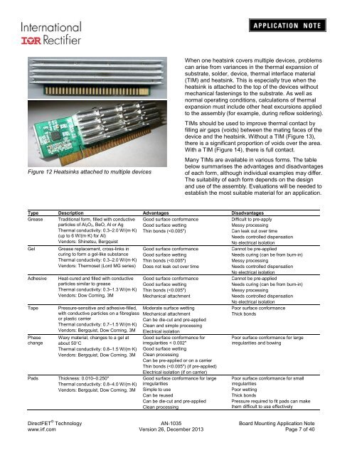
Figure 12 Heatsinks attached to multiple devices<br />
When one heatsink covers multiple devices, problems<br />
can arise from variances in the thermal expansion of<br />
substrate, solder, device, thermal interface material<br />
(TIM) and heatsink. This is especially true when the<br />
heatsink is attached to the top of the devices without<br />
mechanical fastenings to the substrate. As well as<br />
normal operating conditions, calculations of thermal<br />
expansion must include other heat excursions applied<br />
to the assembly (for example, during reflow soldering).<br />
TIMs should be used to improve thermal contact by<br />
filling air gaps (voids) between the mating faces of the<br />
device and the heatsink. Without a TIM (Figure 13),<br />
there is a significant proportion of voids over the area.<br />
With a TIM (Figure 14), there is full contact.<br />
Many TIMs are available in various forms. The table<br />
below summarises the advantages and disadvantages<br />
of each form, although individual examples may differ.<br />
The suitability of each form depends on the design<br />
and use of the assembly. Evaluations will be needed to<br />
establish the most suitable material for an application.<br />
Type Description Advantages Disadvantages<br />
Grease Traditional form, filled with conductive<br />
particles of Al 2O 3, BeO, Al or Ag<br />
Thermal conductivity: 0.3–2.0 W/(m·K)<br />
(up to 6 W/(m·K) for Al)<br />
Vendors: Shinetsu, Bergquist<br />
Good surface conformance<br />
Good surface wetting<br />
Thin bonds (


