

Application Note AN-1035 - International Rectifier
Application Note AN-1035 - International Rectifier
Application Note AN-1035 - International Rectifier

Create successful ePaper yourself
Turn your PDF publications into a flip-book with our unique Google optimized e-Paper software.
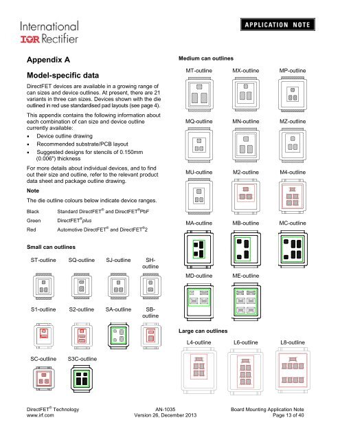
Appendix A<br />
Model-specific data<br />
DirectFET devices are available in a growing range of<br />
can sizes and device outlines. At present, there are 21<br />
variants in three can sizes. Devices shown with the die<br />
outlined in red use standardised pad layouts (see page 4).<br />
This appendix contains the following information about<br />
each combination of can size and device outline<br />
currently available:<br />
• Device outline drawing<br />
• Recommended substrate/PCB layout<br />
• Suggested designs for stencils of 0.150mm<br />
(0.006") thickness<br />
For more details about individual devices, and to find<br />
out their size and outline, refer to the relevant product<br />
data sheet and package outline drawing.<br />
<strong>Note</strong><br />
The die outline colours below indicate device ranges.<br />
Black<br />
Green<br />
Standard DirectFET ® and DirectFET ® PbF<br />
DirectFET ® plus<br />
Red Automotive DirectFET ® and DirectFET ® 2<br />
Medium can outlines<br />
MT-outline MX-outline MP-outline<br />
MQ-outline MN-outline MZ-outline<br />
MU-outline M2-outline M4-outline<br />
MA-outline MB-outline MC-outline<br />
Small can outlines<br />
ST-outline SQ-outline SJ-outline SHoutline<br />
MD-outline<br />
ME-outline<br />
S1-outline S2-outline SA-outline SBoutline<br />
Large can outlines<br />
L4-outline L6-outline L8-outline<br />
SC-outline<br />
S3C-outline<br />
DirectFET ® Technology <strong>AN</strong>-<strong>1035</strong> Board Mounting <strong>Application</strong> <strong>Note</strong><br />
www.irf.com Version 26, December 2013 Page 13 of 40


