

Application Note AN-1035 - International Rectifier
Application Note AN-1035 - International Rectifier
Application Note AN-1035 - International Rectifier

Create successful ePaper yourself
Turn your PDF publications into a flip-book with our unique Google optimized e-Paper software.
Compression tests<br />
Method<br />
• Tests were carried out at ambient room<br />
temperature (22 o C).<br />
• Test speed was:<br />
0.5mmmin -1 for the MQ- and MT-outlines<br />
1.2mmmin -1 for the L8-outline<br />
(return speed of 20mmmin -1 where applicable).<br />
• Test duration was measured from the point at<br />
which the tester registered a force of:<br />
0.05N for the MQ- and MT-outlines<br />
1.00N for the L8-outline.<br />
• The test was terminated if the force reached:<br />
1750N for the MQ- and MT-outlines<br />
2000N for the L8-outline.<br />
Continuous pressure:<br />
Force was applied to the top of the device until the<br />
gate threshold voltage (V g-th ) shifted by ±20% (or until<br />
the maximum force for the outline was reached).<br />
Stepped pressure:<br />
MQ-outline: Force was raised to 400N, relieved and<br />
the device allowed to return to neutral. The force was<br />
then raised to 700N and relieved; this process was<br />
repeated in steps of 50N until the device failed. The<br />
gate threshold was monitored throughout.<br />
MT-outline: The MQ-outline test was replicated but<br />
with an initial force of 600N and increments of 100N.<br />
L8-outline: The MT-outline test was replicated but with<br />
an initial force of 1200N and termination force of<br />
2000N (the maximum available on the equipment).<br />
<strong>Note</strong>: Initial pressures were set close to the expected failure<br />
point to minimize the number of cycles and, therefore, the<br />
fatigue induced by them.<br />
Results<br />
The table below shows the average compression<br />
required to cause failure in DirectFET devices.<br />
MQ-outline MT-outline L8-outline<br />
Continuous 1204N 1407N no failures<br />
Stepped 663N 1106N no failures<br />
<strong>Note</strong>: Gravity (1g) was assumed to be 9.81ms -2 .<br />
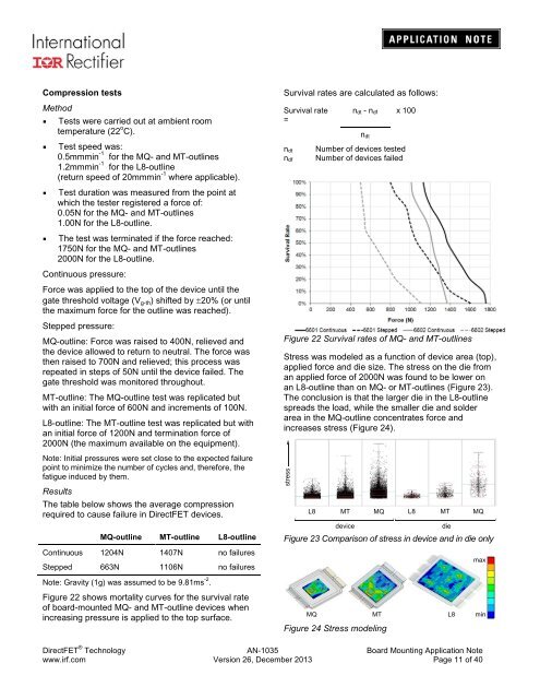
Figure 22 shows mortality curves for the survival rate<br />
of board-mounted MQ- and MT-outline devices when<br />
increasing pressure is applied to the top surface.<br />
Survival rates are calculated as follows:<br />
Survival rate<br />
=<br />
n dt<br />
n df<br />
n dt - n df x 100<br />
n dt<br />
Number of devices tested<br />
Number of devices failed<br />
Figure 22 Survival rates of MQ- and MT-outlines<br />
Stress was modeled as a function of device area (top),<br />
applied force and die size. The stress on the die from<br />
an applied force of 2000N was found to be lower on<br />
an L8-outline than on MQ- or MT-outlines (Figure 23).<br />
The conclusion is that the larger die in the L8-outline<br />
spreads the load, while the smaller die and solder<br />
area in the MQ-outline concentrates force and<br />
increases stress (Figure 24).<br />
stress<br />
L8 MT MQ L8 MT MQ<br />
device die<br />
Figure 23 Comparison of stress in device and in die only<br />
MQ MT L8<br />
Figure 24 Stress modeling<br />
max<br />
min<br />
DirectFET ® Technology <strong>AN</strong>-<strong>1035</strong> Board Mounting <strong>Application</strong> <strong>Note</strong><br />
www.irf.com Version 26, December 2013 Page 11 of 40


